Citroen CX 1982 1.G Workshop Manual
Manufacturer: CITROEN, Model Year: 1982, Model line: CX, Model: Citroen CX 1982 1.GPages: 394
Page 311 of 394

Downloaded from www.Manualslib.com manuals search engine
Page 312 of 394
Downloaded from www.Manualslib.com manuals search engine Op. MA. 510-00 b 5
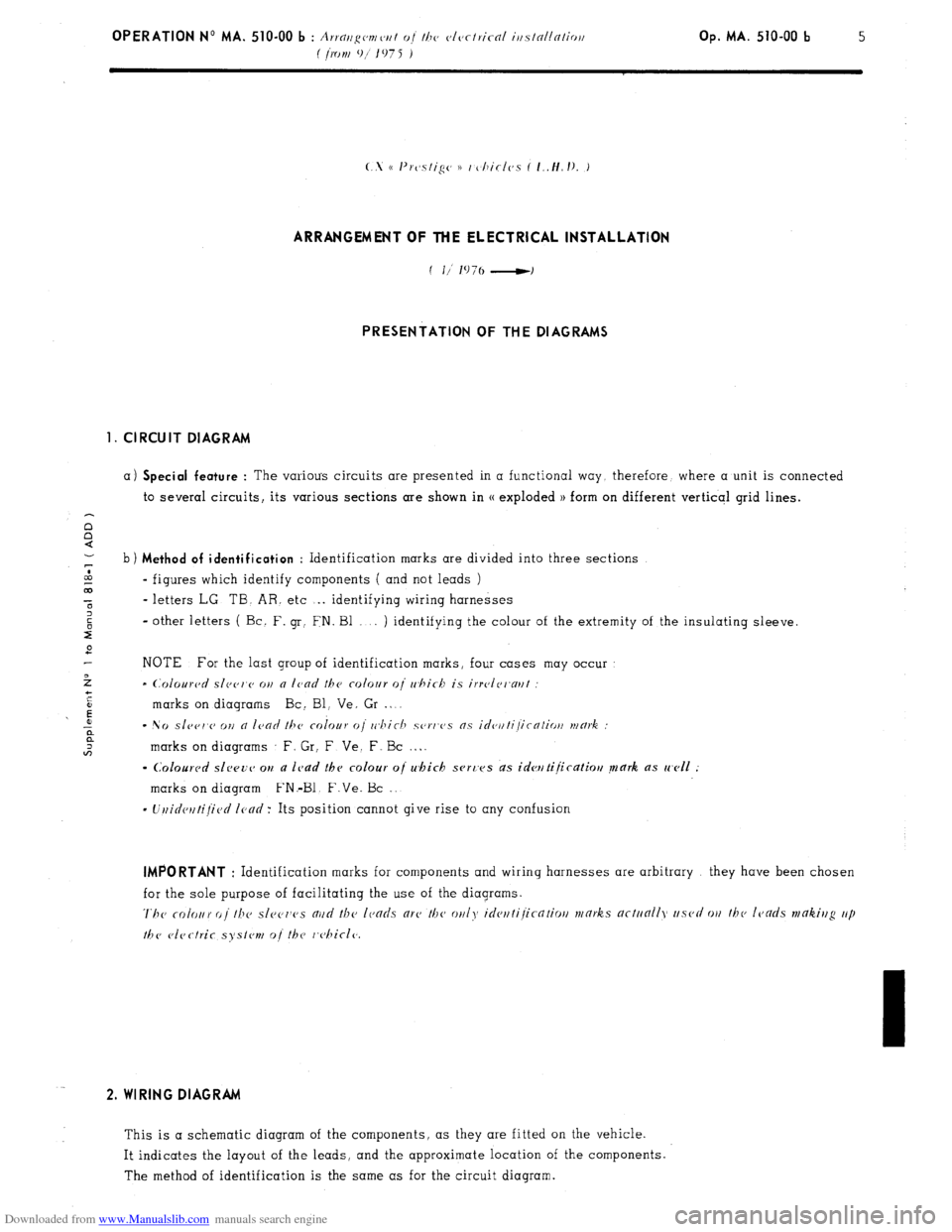
ARRANGEMENT OF THE ELECTRICAL INSTALLATION
PRESENTATION OF THE DIAGRAMS
1. CIRCUIT DIAGRAM
a) Special feature : The various circuits are presented in a functional way. therefore, where a unit is connected
to several circuits, its various sections are shown in (( exploded 1) form on different verticql grid lines.
b) Method of identification
: Identification marks are divided into three sections
CA
- figures which identify components ( and not leads )
00
t - letters LG. TB. AR. etc . . identifying wiring harnesses
2
2 - other letters ( Bc. F. gr: FN. Bl . . ) identifying the colour of the extremity of the insulating sleeve.
2
NOTE For the last group of identification marks, four cases may occur
>
- (~~olourc~d slec~r~c~ on a lcad the colour 0i whirb is irrvlri~aul
+
i
t
’ E marks on diagrams Bc: Bl, Ve, Gr . L
r: - No sle~r,c> OII n ICOO ~hc colour (Ii rr~hic-h sorws ns idc~~lti/icntio~/ mmk :
;: marks on diagrams F. Gr, F Ve. F. Bc . . .
- Colourc~d slwv~~ ou a lc,ad thv colour oj which svrc’es ds idwtijicatiou mark as well :
marks on diagram FN.-Bl. F.Ve. Bc ,.
- Uuidctltijied Icncl: Its position cannot give rise to any confusion IMPORTANT
: Identification marks for components and wiring harnesses are arbitrary they have been chosen
for the sole purpose of facilitating the use of the diagrams.
The rofour oi the sl~~c~ws nud the lends arc’ the on/?, ideuti/icntio// works actunlly used WI thv leads mtikiug up
the vlectrir syslvn, o/ the r,c,hicl(~. 2. WIRING DIAGRAM
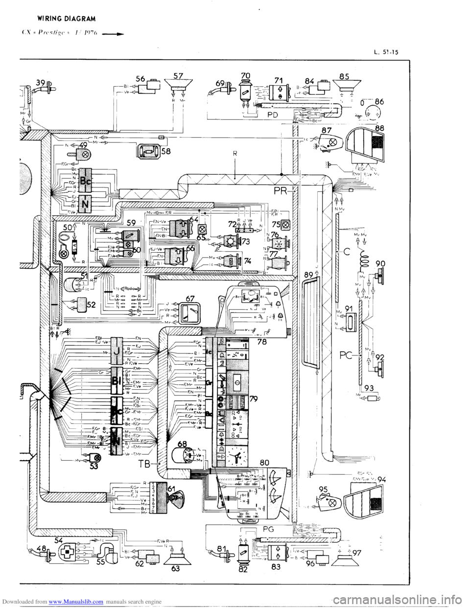
This is a schematic diagram of the components, as they are fitted on the vehicle.
It indicates the layout of the leads, and the approximate location of the components.
The method of identification is the same as for the circuit diagram.
Page 313 of 394
Downloaded from www.Manualslib.com manuals search engine TABLE OF FUSES
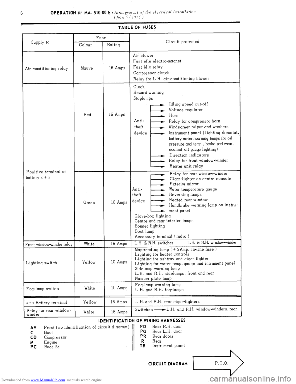
Supply to Fuse
Colour Rating Circuit protected
‘Air blower
Fast idle electro-magnet
Air-conditioning relay Mauve 16 Amps Fast idle relay
Compressor clutch
Relay for L.H. air-conditioning blower
Positive terminal of
battery (( t )) Red
Green Clock
Hazard warning
Stoplamps
Idling speed cut-off
Voltage regulator
16 Amps
I’ Horn
Anti-
Relay for compressor horn
theft Windscreen wiper and washers
device Instrument panel (lighting rheostat
battery meter. warning lamps for oil
pressure and temp., brake pad wear,
coolant, oil gauge lighting)
Direction indicators
Relay for front window-winder
Heater unit relay
E Relay for rear window-winder
Cigar-lighter on centre console
Exterior mirror
Anti- Water temperature gauge
theft Reversing lamps
16 Amps device Heated rear window
Handbrake warning lamp on instru-
ment panel
Glove-box lighting
Centre and rear interior lamps
Bonnet lighting
Boot lamp
Accessory terminal (radio 1
Front window-winder relay
Lighting switch White
Yellow 16 Amps L.H. & R.H. switches L.H. 6 RH. window-winder
Map-reading lamp ( + 5Amp. in-line fuse )
Lighting for heater controls
10 Amps Lighting for ashtray and cigar lighter
Lighting for water temp. gauge and intrument panel
Sidelamp warning lamp
L.H. and R.H. sidelamps. front and rear
Number plate lamp
Fog-lamp switch White 10 Amps Fog-lamp warning lamp
L.H. and R.H. fog-lamps
(( + 1) Battery terminal
Relay for rear window-
winder Yellow
White 16 Amps L.H. and R.H. rear cigar-lighters
16 Amps Switches -L.H. and R.H. window-winders, rear
-.. -- . ..-...- . . . -..---m-
IDENTIFICATION
OF WIRING HARNt33t3
AV Front ( no identification of circuit diagram) PD Rear R.H. door
C Boot PG
Rear L.H. door
co Compressor PR
Rear doors
M Engine Rear PC
Boot lid TRS Instrument panel Cl RCUI T DIAGRAM
L3
P.T.O.
Page 314 of 394

Downloaded from www.Manualslib.com manuals search engine
Page 315 of 394

Downloaded from www.Manualslib.com manuals search engine
Page 316 of 394
Downloaded from www.Manualslib.com manuals search engine OPERATION No MA. 510-00 b : i
.,.~//,q~~r~/~/// o/ //IV ~,lc,ctrit 01 iti.sfnl/nlio,l Op. MA. 510-00 b 7
I /IONI 9
1075 )
dent,
lark
1
2
7
8
9
10
11
12
13
14
15
16
17
18
19
20
21
22
23
24
25
26
27
28
29
30
31
32
33
34
35
36
37
38
39
40
41
42
43
44
45
46
47
48
49
50
51
52
53
54
55
56
57
58
59
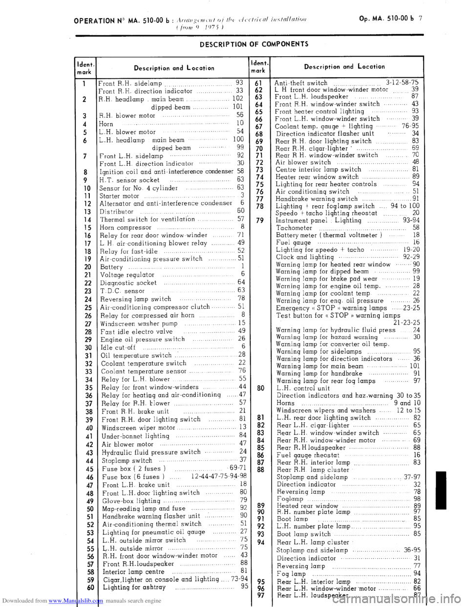
60 DESCRIPTION OF COMPONENTS
Description and Location
‘rant R.H. sidelamp 93 .........................
‘rant R.H. direction indicator .............
33
3 .H. headlamp main beam ............... 102
dipped .beam ............... 101
3.H. blower motor .......... ........ ...... 56
iorn ....... ...... ....
........................... 10
,,H, blower motor ...........................
54
,.H. headlamp main beam .................. 100
dipped beam ........... 99
‘rant L.H. sidelamp ........................
92
Front L.H. direction indicator ................ 30
[gnition coil and anti-interference condenser 58
‘I.T. sensor socket .............................
63
jensor for No. 4 cylinder ................
63
5tarter motor .......................... 3
41ternator and anti-interference condenser 6
Distributor ...... ......................
60
Thermal switch for ventilation ............ 57
Horn compressor ................................ 8
Relay for rear door window winder ....... 71
L H. air conditioning blower relay ............
49
Relay for fast-idle ........................... 52
Air-conditioning pressure switch ............ 51
Battery ...............................
1
Voltage regulator ..................... 6
Diagnostic socket ...................... 64
T.D.C. sensor .......................... 63
Reversing lamp switch ......................
78
Air-conditioning compressor clutch.. ........
51
Relay for compressed air horn ............... 8
Windscreen washer pump ......... ........ 15
Fast idle electro valve ......................
49
Engine oil pressure switch ............... 26
Idle cut-off ...................................
6
Oil temperature switch .: ....................
28
Coolant temperature switch ............
22
Coolant temperature sensor ...............
76
Relay for L.H. blower ....................... 55
Relay for front window-winders ............
44
Relay for heating and air-conditioning
.... ..4 7
Relay for F.H. tlower ........................
57
Front R H. brake unit .........................
21
Front R.H. door lighting switch ............ 81
Windscreen wiper motor ...........................
13
Under-bonnet lighting. ..................... ..... 84
Air blower motor ...................................... 47
Hydraulic fluid pressure switch ............ 24
Stoplamp switch ..................................
37
Fuse box ( 2 fuses ) ......................
69-71
Fuse box (6 fuses ) ..... 12-44-47-75-94-98
Front L.H. brake unit ............................
18
Front L.H. door ‘lighting switch .............
80
Glove-box lighting ................................. 79
Map-reading lamp and fuse .....................
92
Handbrake warning flasher unit ..............
90
Air-conditioning thermal switch .......... 51
Lighting for pneumatic oil gauge ............
27
L.H. outside mirror switch ................
75
&.H. outside mirror ................................. 75
R.H. front door window-winder motor ...... 43
Front R.H.loudspeaker ....................... 88
Interior lamp centre .............................. 81
Cigar,lighter on console and lighting .... 73-94
Lighting for ashtray .............................. 95 dent.
lark
2
63
b:
66
67
68
69
3:
5;
5:
76
77
78
79
80
to9
8:
93
94
95
99s Description and Location
Anti-theft switch
.._.. _..,..... _. 3-12-58-75
L H front door window-winder motor i;
Front L.H. loudspeaker
Front R.H. window-winder switch ....... .... 43
Front heater control lighting ..............
93
Front L.H. window-winder switch
........ 39
Coolant temp. gauge + lighting
........ 76-95
Direction indicator flasher unit ......... 34
Rear R.H. door lighting switch
................ 83
Rear R.H. cigar-lighter ’ ...................
69
Rear R H. window-winder switch
........ 70
Air blower switch ...............................
48
Centre interior lamp switch
.................. 81
Heater rear window switch
...................... 89
Lighting for rear heater controls
....... 94
Air conditioning switch
................
51
Handbrake warning switch
....................
91
Light.ing t rear foglamp switch
.... 94 to 100
Speed0 t tacho lighting rheostat
....... 20
Instrument panel
Lighting .............. 93-94
Tachometer
........................................ 58
Battery meter ( thermal voltmeter )
.....
18
Fuel gauge .., ................... ...................... 16
Lighting for speed0 + tacho
............. 19-20
Clock and lighting ........... ...............
92-29
Warning lamp for heated rear window
...... 90
Warning lamp for dipped beam
............. 99
Warning lamp for bt-ake pad wear
.......... 19
Warning lamp for engine oil temp. .......... 28
Warning lamp for coolant temp
..........
22
Warning lamp for eng. oil pressure ......... 26
Emergency (( STOP )) warning lamps
... ...23-2 5
Test button for (( STOP )) warning lamps
21-23-25
Warning lamp for hydraulic fluid press ..7.4
Warning lamp for hazard warning 30
Warnina lamu for converter oil temo.
Warnin; lamb for sidelamps
..... : ..........
95
Warning lamp for direction indicators
.... 36
Warning lamp for main beam
................. 101
Warning lamp for handbrake
....................
91
Warning lamp for rear fog lamps ........... 97
L.H. control unit
Direction indicators and haz.warning 30 to35
Horns ... ........................................
9 and 10
Windscreen wipers and washers
.... 12 to 15
L.H. rear door lighting switch
................
82
Rear L.H. cigar-lighter
............................ 65
Rear L.H. window-winder switch
............ 65
Rear R.H. window-winder motor
......... 69 Rear Re H loudspeaker
............................ 88
Fuel gauge rheostat ....................... .....
16
Rear R.H. interior lamp
......................
83
Rear R.H lamp cluster
Stoplamp and sidelamp
................ ... 37-97
Direction indicator .............................. 32
Reversing lamp ...................................
78
Foglamp .................................................
98
Heated rear window
.................................. 89
R.H. number plate lamp
97 ..........................
Boot lamp
.......................................
85
L.H. number plate lamp.. ..........................
95
Boot lamp switch
.............................. 85
Rear L.H. lamp cluster Stoplamp and sidelamp
....................... X6-95
Direction indicator ......................... ........
31
Reversing lamp
.......................
................
Fog lamp
.................................................. ii
Rear L.H. interior lamp ............................
Rear L.H. window-winder’motor
............. 68;
Rear L.H. loudspeaker ............................ 87
Page 317 of 394
Downloaded from www.Manualslib.com manuals search engine TABLE OF BULBS
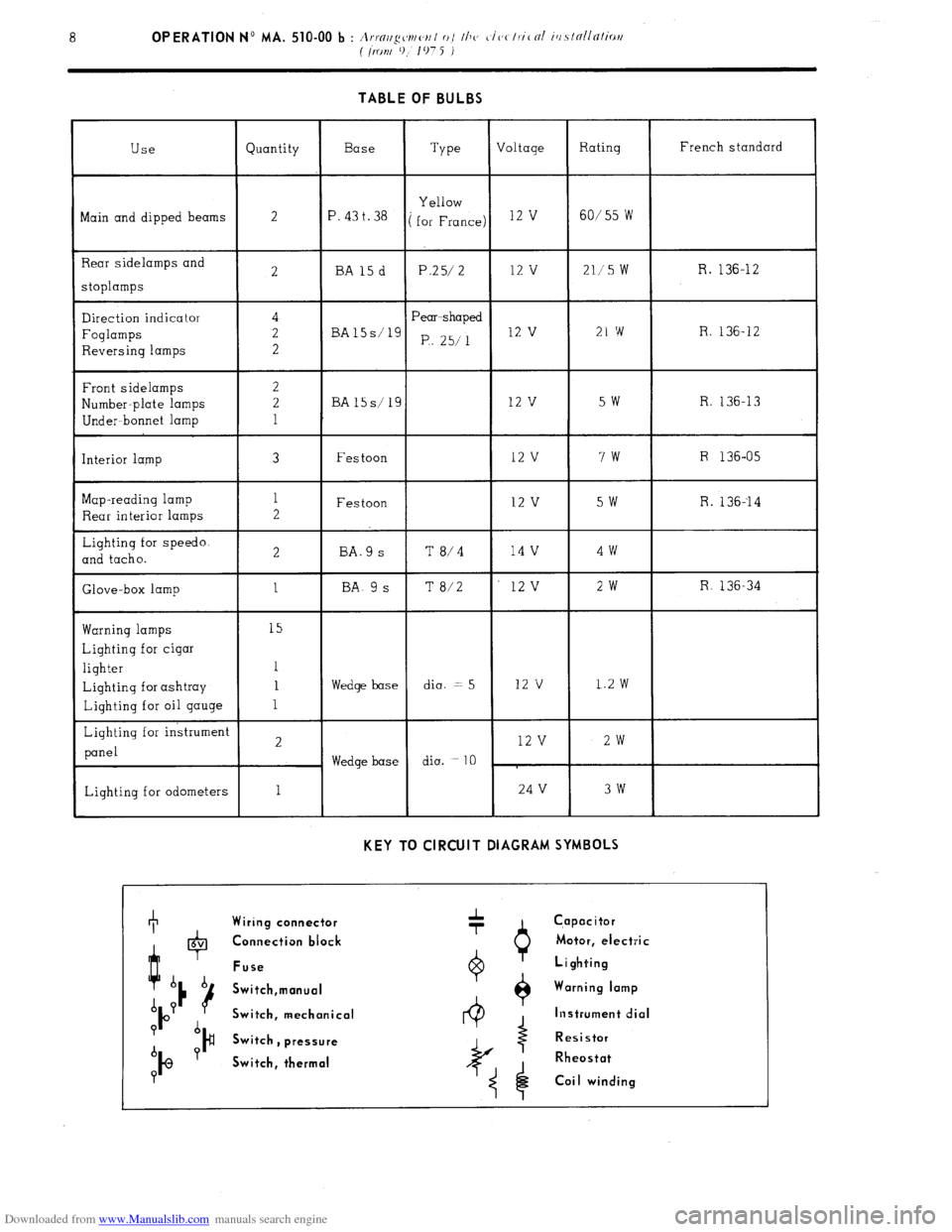
Use Quantity Base
Type Voltage Rating French standard
Bain and dipped beams Yellow
2
‘. 43 t. 38 ( for France) l2 ’ 60/55 W
3ear sidelamps and
3tOplamps
2 BA15d P.25/ 2 12 v 211’5 W R. 136-12
Direction indicator
Foglamps
Reversing lamps
Front sidelamps
yumber-plate lamps
Under- bonnet lamp
[nterior lamp
Wap-reading lamp
Rear interior lamps
Lighting for speedo.
2nd tacho.
Slave-box lamp 4
2
2
2
2
1
3
1
2
2
1 Pear-shaped
BA15s’1g
P,. 25/l 12 v 21 w R. 136-12
BA15s/19 12 v 5w R. 136-13
Festoon 12 v 7w R 136-05
Festoon 12 v 5W R. 136--14
BA.9 s T 8/4 14 v 4w
BA. 9 s T 8/2 12v 2w R 136-34
tiarning lamps 15
Lighting for cigar
lighter 1
Lighting for ashtray 1 Wedge base dia. = 5 12 v 1.2 w
Lighting for oil gauge 1
Lighting for instrument
2 12 v 2w
panel
Wedge base diu. =
10
Lighting for odometers 1 24 V 3w
KEY TO CIRCUIT DIAGRAM SYMBOLS +
Wiring connector A
-r C,apacitor
t 0 6V Connection block Motor, electric
Fuse Lighting
b b
16 Switch,manual Warning lamp
A P
P Switch, mechanical Instrument dial
? b
)# Switch
b Y , pressure Resistor
IQ Switch, thermal Rheostat
P
Coi I winding
Page 318 of 394

Downloaded from www.Manualslib.com manuals search engine
Page 319 of 394
Downloaded from www.Manualslib.com manuals search engine
Page 320 of 394

Downloaded from www.Manualslib.com manuals search engine OPERATION N” MA. 510-00 b : A ..n A II it ~(~rttc~t7t 0 j lhv cJcctr.ical irlsldllntiari ( iront 9/
107 5 ) Op. MA. 510-00 b 9
ARRANGEMENT OF THE ELECTRICAL INSTALLATION
PRESENTATION OF THE DIAGRAMS
1. CIRCUIT DIAGRAM
a) Special feature
: The various circuits are presented in a functional way. therefore. where a unit is connected
to several circuits. its various sections are shown in cx exploded )) form on different vertical grid lines.
n
0 b) Method of identification, Identification marks are divided into three sections
<
- figures which identify components ( and not leads )
- letters LG, TB! AR. etc .~. identifying wiring harnessss,
- other letters ( Bc F. Gr, FN. Bl . . . ) identifying the colour of the extremity of the insulating sleeve.
:
r”
NOTE For the last group of identification marks. four cases may occur
marks on diagrams Bc. Bl. Ve. Gr . ..~
- No
slcc~rv ot) a lcad tbv colaur o{ which scrt‘vs as idvtltijirntiatt mark :
marks on diagrams F. Gr. F. Ve. F. Bc . . . .
- UnidetttijiGd lead : its position cannot give rise to any confusion. IMPORTANT
: Identification marks for components and wiring harnesses are arbitrary they have been chosen
for the sole purpose ‘of facilitating the use of the diagrams.
7’hr colour of tkc sl~~c~r~c~s aud tbcz IcJads arc the wly idcwtijicntiorl marks nctr,ally used ot1 the leads mak.fng
up the elcactric systc~nz 0 / th(z chicle. 2. WIRING DIAGRAM
This is a schematic diagram of the components. as they are fitted on the vehicle.
It indicates the layout of the leads, and the approximate location of the components
The method of identification is the same as for the circuit diagram.