length Citroen CX 1983 1.G User Guide
[x] Cancel search | Manufacturer: CITROEN, Model Year: 1983, Model line: CX, Model: Citroen CX 1983 1.GPages: 394
Page 66 of 394
Downloaded from www.Manualslib.com manuals search engine OPERATION No MA. 100-00 : Characteristics and special features of the engine. Op. MA. 100.00 15
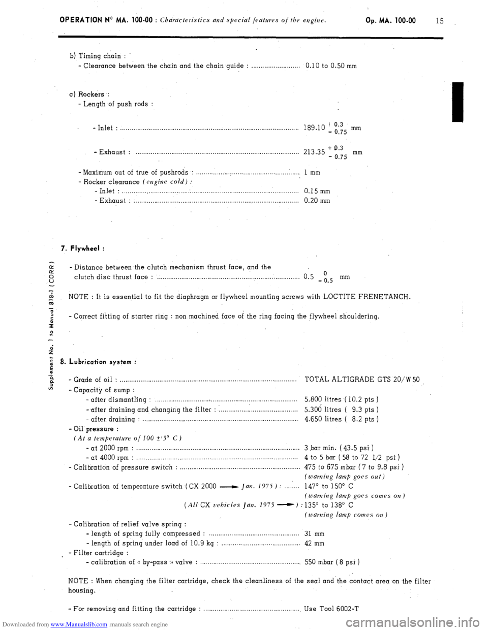
b) Timing chain :
- Clearance between the chain and the chain guide : . . . . . . . . . . . . . . . . . . . . . . . . . . 0.10 to 0.50 mm
c) Rockers :
- Length of push rods :
- Inlet : . . . . . . . . . . . . . . . . . . . . . . . . . . . . . . . . . . . . . . . . . . . . . . . . . . . . . . . . . . . . . . . . . . . . . . . . . . . . . . . . . . . . . . . . . . . . . . 189.10 ‘, Og’Q5 mm
- Exhaust : . . . . . . . . . . . . . . . . . . . . . . . . . . . . . . . . . . . . . . . . . . . . . . . . . . . . . . . . . . . . . . . . . . . . . . . . . . . . . . . . . . . . . . . 213.35 + 0.3
- 0.75 mm
- Maximum out of true of pushrods : . . . . . . . . . . . . . . . . . . . . . . . . . . . . . . . . . . . . . . . . . . . . . . . . . . . . . . . 1 mm
- Rocker clearance (engine cold) :
-Inlet : . . . . . . . . . . . . . . . . . . . . . . . . . . . . . . . . . . . . . . . . . . . . . . . . . . . . . . . . . . . . . . . . . . . . . . . . . . . . . . . . . . . . . . . . . . . . . . 0.15mm
- Exhaust : . . . . . . . . . . . . . . . . . . . . . . . . . . . . . . . . . . . . . . . . . . . . . . . . . . . . . . . . . . . . . . . . . . . . . . . . . . . . . . . . . . . . . . . . 0.20 mm
7. Flywheel :
2 - Distance between the clutch mechanism thrust face, and the 0 u clutch disc thrust face : . . . . . . . . . . . . . . . . . . . . . . . . . . . . . . . . . . . . . . . . . . . . . . . . . . . . . . . . . . . . . . . . . . . . . . . . . . . . 0.5 -is mm
7
co
G NOTE : It is essential to fit the diaphragm or flywheel mounting screws with LOCTITE FRENETANCH.
x
z - Correct fitting of starter ring : non machined face of the ring facing the flywheel shouldering.
s
2
E 8. Lubrication system :
5
z
6%
- Grade of oil . . . . . . . . . . . . . . . . . . . . . . . . . . . . . . . . . . . . . . . . . . . . . . . . . . . . . . . . . . . . . . . . . . . . . . . . . . . . . . . . . . . . . . . . . . . . . . . TOTAL ALTIGRADE GTS 20/W 50
2
- Capacity of sump :
- after dismantling : . . . . . . . .._................................................................. 5.800 litres ( IO.2 pts )
- after draining and changing the filter : : . . . . . . . . . . . . . . . l......................... 5.306 litres ( 9.3 pts )
- after draining : . . . . . . . . . . . . . . . . . . . . . . . . . . . . . . . . . . . . . . . . . . . . . . . . . . . . . . . . . . . . . . . . . . . . . . . . . . . . . . . . . . . 4.650 litres ( 8.2 pts )
- Oil pressure :
(At a temperature of 100 +‘S’ C)
- at 2000 rpm : . . . . . . . . . . . . . . . . . . . . . . . . . . . . . . . . . . . . . . . . . . . . . . . . . . . . . . . . . . . . . . . . . . . . . . . . . . . . . . . . . . . . . . . 3 .bar min. ( 43.5 psi )
- at 4000 rpm : . . . . . . . . . . . . . . . . . . . . . . . . . . . . . . . . . . . . . . . . . . . . . . . . . . . . . . . . . . . . . . . . . . . . . . . . . . . . . . . . . . . . . . 4 to 5 bar ( 58 to 72 l/2 psi )
- Calibration of pressure switch : . . . . . . . . . . . . . . . . . . . . . . . . . . . . . . . . . . . . . . . . . . . . . . . . . . . . . . . . . . . . . . . . 475 to 675 mbar ( 7 to 9.8 psi )
(warning lamp goes oat)
- Calibration of temperature switch (CX 2000 e Jan. 1975) : . . . . 1... 147’ to 150’ C
(warning lamp goes comes on)
(All CX vehicles Jan. 1975 -) : 135” to 138’ C
(warning lamp comes on )
- Calibration of relief valve spring :
- length of spring fully compressed : . . . . . . . . . . . . . . . . . . . . . . . . . . . . . . . . . . . . 31 mm
- length of spring under load of 10.9 kg : . . . . . . . . . . . . . . . . . . . . . . . . . . . . . . . . . . . . . . . . . . 42 mm
- Filter cartridge :
- calibration of (( by-pass )) valve : . . . . . . . . . . . . . . . . . . . . . . . . . . . . . . . . . . . . . . . . . . . . . . . . . . . . . . 550 mbar ( 8 psi )
NOTE : When changing the filter cartridge, check the cleanliness of the seal and’the contact area on the filter
housing.
- For removing and fitting the cartridge : . . . . . . . . . . . . . . . . . . . . . . . . . . . . . . . . . . . . . . . . . . . . . . . . . . . . Use Tool 6002-T
Page 95 of 394
Downloaded from www.Manualslib.com manuals search engine CHECKING THE DEVICE FOR OPENING THE
BUTTERFLY
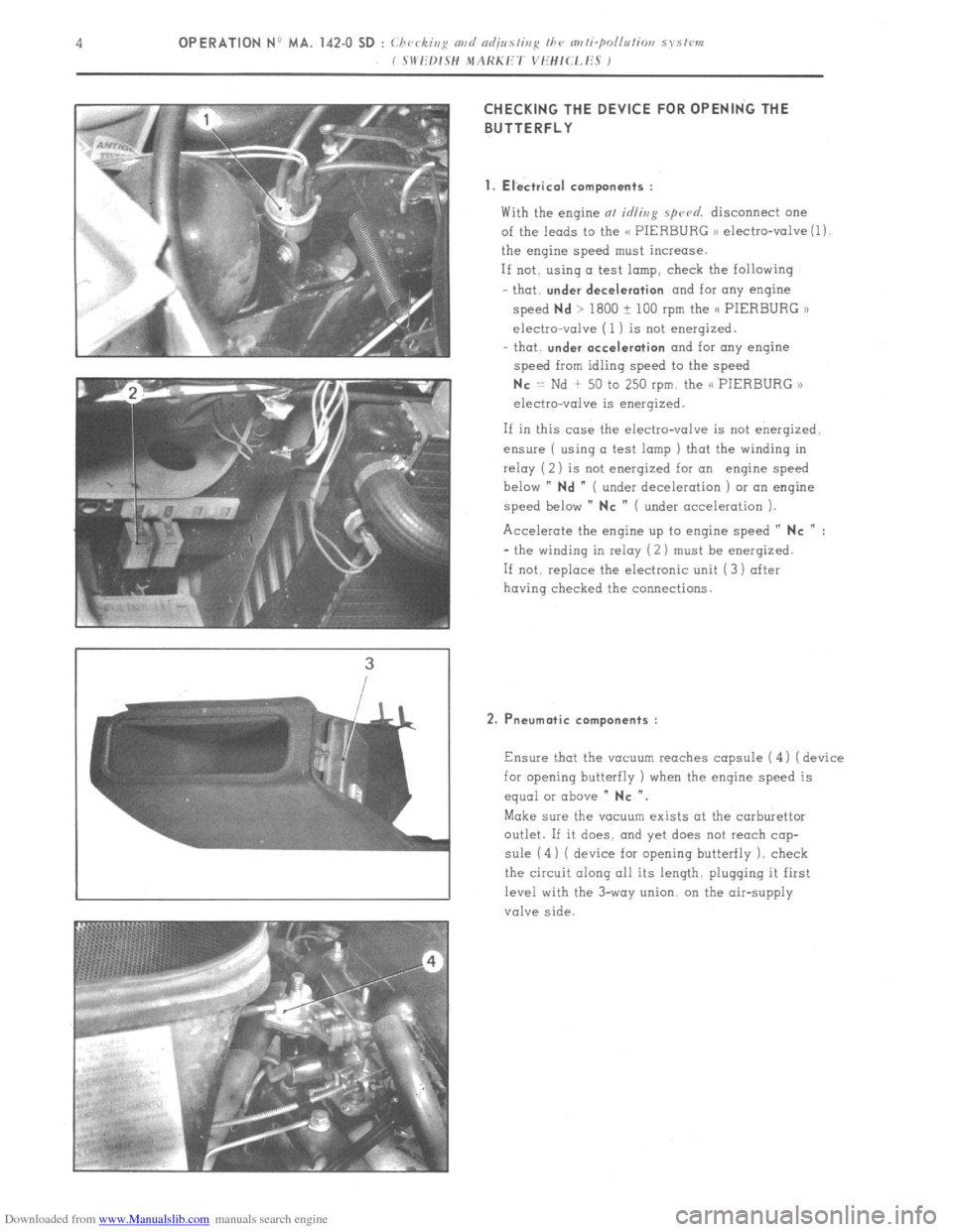
1. Electrical components :
With the engine at idling spu~d. disconnect one
of the leads to the C< PIERBURG ,) electro-valve (1).
the engine speed must increase.
If not. using a test lamp, check the following
that.
under deceleration and for any engine
speed
Nd > 1800 ? 100 rpm the /C PIERBURG >l
electro-valve (1 ) is not energized.
- that.
under acceleration and for any engine
speed from idling speed to the speed
Nc = Nd + 50 to 250 rpm. the C< PIERBURG ,,
electro-valve is energized.
If in this case the electro-valve is not energized.
ensure ( using a test lamp ) that the winding in
relay ( 2) is not enerqized for an engine speed
below ”
Nd ” ( under deceleration ) or an engine
speed below ”
NC ” ( under acceleration ).
Accelerate the engine up to engine speed ”
NC n :
- the winding in relay (2 ) must be enerqized.
If not. replace the electronic unit (3) after
having checked the connections.
2. Pneumatic components :
Ensure that the vacuum reaches capsule ( 4 1 ( device
for opening butterfly ) when the engine speed is
equal or above ”
NC “.
Make sure the vacuum exists at the carburettor
outlet. If it does. and yet does not reach cap-
sule (4) ( device for opening butterfly 1. check
the circuit along all its length. plugging it first
level with the 3-way union. on the air-supply
valve side.
Page 150 of 394
Downloaded from www.Manualslib.com manuals search engine OPERATION No MA. 173-O : Chrrkivp fhr prmd s,,pp/> Op. MA. 173.0 1
PETROL PUMP
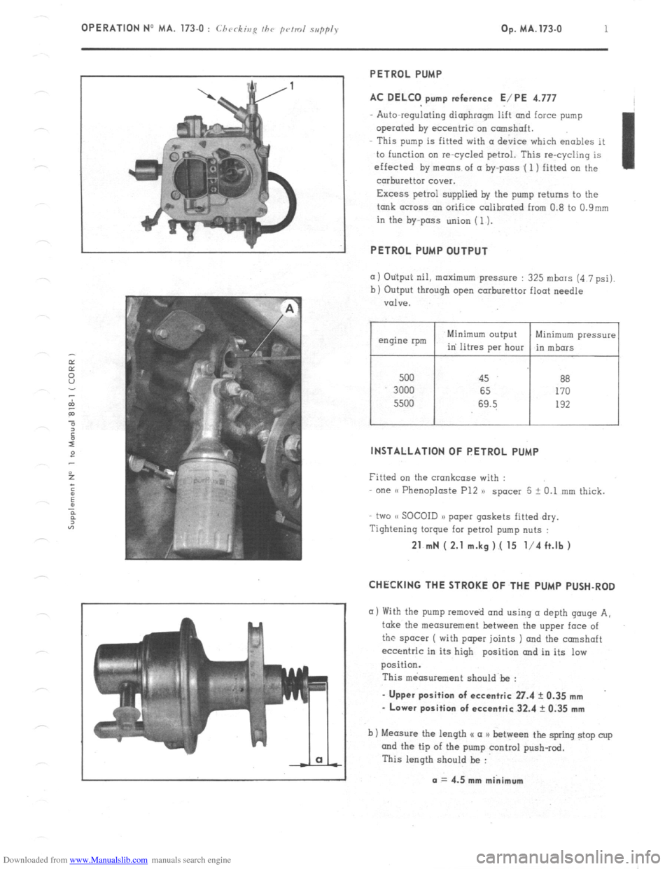
AC DELCO pump reference E/PE 4.777
Auto-regulating diaphragm lift and force pump
operated by eccentric on camshaft.
This pump is fitted with (I device which enables it
to function on re-cycled petrol. This re-cycling is
effected by means of a by-pass .( 1 ) fitted on the
carburettor cover.
Excess petrol supplied by the pump returns to the
tank across an orifice calibrated from 0.8 to 0.9mm
in the by-pass union (1).
PETROL PUMP OUTPUT
(I) Otitput nil, maximum pressure : 325 mbars (4 7 psi).
b) Output through open carburettor float needle
valve.
500 45 88
3000 65 170
5500 69.5 192
I I
Minimum pressure
in mbors
INSTALLATION OF PETROL PUMP
Fitted on the crankcase with :
one (( Phenoploste P12 )) spacer 5 + 0.1 mm thick.
two (< SOCOID a> paper gaskets fitted dry.
Tightening torque for petrol pump nuts :
21 mN ( 2.1 m.kg ).( 15 l/4 ft.lb )
CHECKING THE STROKE OF THE PUMP PUSH-ROD
a) With the pump removed and using (I depth gouge A,
take the measurement between the upper face of
the spacer ( with paper joints ) and the camshaft
eccentric in its high position and in its low
position.
This measurement should be :
- Upper position of eccentric 27.4 ? 0.35 mm
- Lower position of eccentric 32.4 rk 0.35 mm
b) Measure the length u a a) between the spring stop cup
and the tip of the pump control push-rod.
This length should be :
a = 4.5 mm minimum
Page 153 of 394
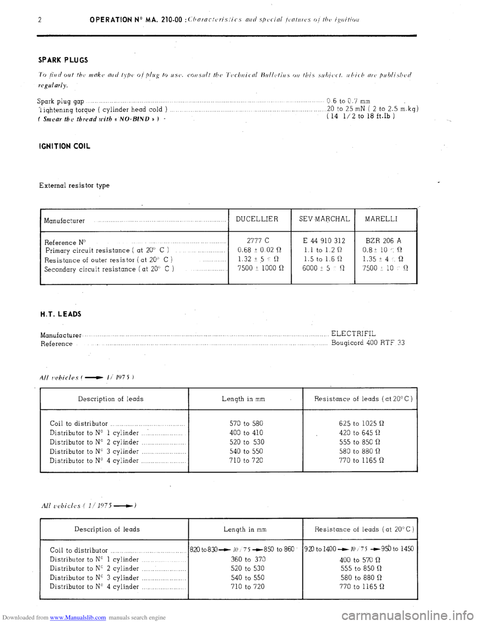
Downloaded from www.Manualslib.com manuals search engine 2 OPERATION No MA. 210-00 :~~‘hornc:cris:ics mri special /~~nttrrc,.s o,/ /he ig/litiorl Spark plug gap .,...._.......,...,. ,..._. ,...... ., ,, ,,
Q.6 to 0.7 mm
1 iqhtenrng torque ( cylinder head cold ) .._..._._........._.......... .20 to 25 mN ( 2 to 2.5 m.kg)
f Smear the thread with e NO-BIND n ) - ( 14 l/2 to 18 ft.Ib ) IGNITION COIL
External resistor type
I Manufacturer
I DUCELLIER
I SEV MARCHAL
I MARELLI
Reference N” 2777 C E 44 910 312 BZR 206 A
Primary circuit resistance ( at 20” C ) 0.68 i 0.02 n 1.1 to 1.2 Q 0.8+ 10 .: ,R
Resistance of outer resistor (at 20” C ) 1.32 + 5 ‘; R 1.5 to 1.6 R 1.35 i 4 . . R
Secondary circuit resistance (at 20” C ) 7500 2 1000 n
6000 -!I 5 Cl 7500 + 10 !’ Q H.T. LEADS
Length in mm Resistance of leads ( at 20” C )
Manufacturer. .................. .......................................................... ..................................................... ELECTRIFIL
Reference ..................... ............. ........... ....... ....... ... ........................ ............ ......... Bougicord 400 RTF 33
All rY?biclas ( - I/’ 1975 1
Description of leads
Coil to distributor ............................ ...........
Distributor to No 1 cylinder ... . ..................
Distributor to No 2 cylinder .......................
Distributor to N” 3 cylinder ........................
Distributor to N” 4 cylinder ........................ 570 to 580 625 to 1025 !J
400 to 410 420 to 645 11
520 to 530 555 to 850 11
540 to 550 580 to 880 Q
710 to 720 770 to 1165 Q
I I I
Description of leads Length in mm
I Resistance of leads ( at 20” C )
Coil to distributor ......................................... 820 to83O- 10 1 75 -859 to 860
Distributor to No 1 cylinder ..................... 360 to 370
Distributor to N” 2 cylinder ........................ 520 to 530
Distributor to NC 3 cylinder ....................... 540 to 550
Distributor to N” 4 cylinder
...................... 710 to 720 920 to 1400 - 10 175 -93.3 to 1450
400 to 570 n
555 to 850 R
580 to 880 Q
770 to 1165 Q
I I 1
Page 155 of 394
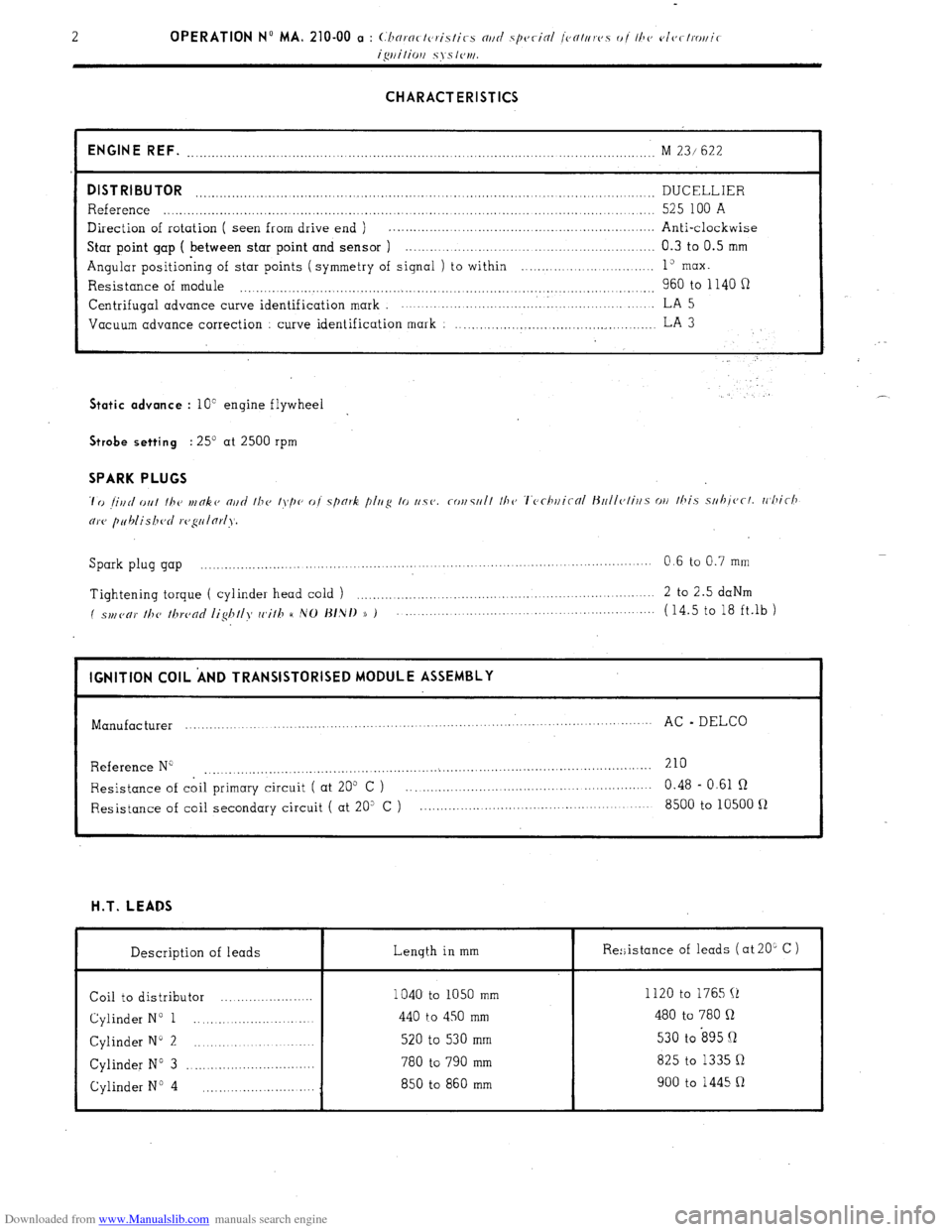
Downloaded from www.Manualslib.com manuals search engine CHARACTERISTICS
ENGINE REF.
........................................................................................... ........................ M 23/ 622
DISTRIBUTOR DUCELLIER ..................................................................................................................
Reference ..................................................................................................................... 525 100 A
Direction of rotation ( seen from drive end ) . .................................................................
Anti-clockwise
Star point gap ( between star point and sensor ) .............................................................. 0.3 to 0.5 mm
Angular positioning of star points ( symmetry of signal ) to within ........... ... ... ....... ..... 1” max.
Resistance of module 960 to 1140 fi .................................................................................................. Centrifugal
advance curve identification mark ................................. . ..................... LA 5
Vacuum advance correction
curve identification mark : ..................................................
LA 3 Static advance
: 10” engine flywheel . .’ Strobe setting
: 25’ at 2500 rpm SPARK PLUGS
Spark plug gap ................. ....
.................... ................... ....... 0.6 to 0.7 mm
......................... .........
Tightening torque ( cylinder head cold ) ....................................................................
2 to 2.5 daNm
( spl,(,c,)’ //T(, /hrc,nc/ /ig/T//>f cc,i//T H ,VO J~/,N/) )) ) ...................................................... (14.5 to 18 ft.lb )
I IGNITION COIL ‘AND TRANSISTORISED MODULE ASSEMBLY
I
Manufacturer ...............
................... ........ .............. .............. .......
AC - DELCO
...........................
Reference N” 210
....................................................... ...
....................................................
Resistance of coil primary circuit ( at 205 C ) ............................................................ 0.48 - 0.61 R
Resistance of coil secondary circuit ( at 20” C ) ......................................................... 8500 to 10500 fl H.T. LEADS
Description of leads Length in mm
Coil to distributor ....................... 1040 to 1050 mm
Cylinder N” 1 ............................ 440 to 450 mm
Cylinder N” 2 ............................. 520 to 530 mm
Cylinder N” 3 ................................ 780 to 790 mm
Cylinder No 4 850 to 860 mm
............................ Re:;istance of leads ( at 20L C )
I
1120 to 1765 (1
480 to 780 Q
530 to s95 Q
825 to 1335 Q
900 to 1445 R
Page 178 of 394
Downloaded from www.Manualslib.com manuals search engine OPERATION No MA. 230.0 : M k
08 ,ri,y r,i, //I<’ roo/i,ip c, s,w,,.
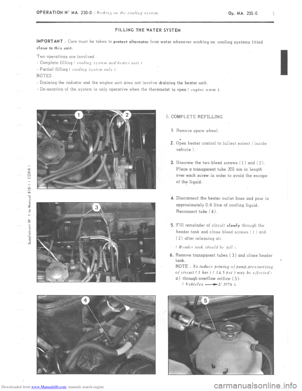
Op. MA. 230.0 1 FILLING THE WATER SYSTEM
IMPORTANT
: Core must be token to protect alternator from water whenever working on cooling systems fitted close to this unit.
Two operations are involved
- Complete filling i roolir~g c~s~<,v, nvd bvolvr ,,ail ,
- Partial filling I roolir,p ~J~S/IW, oul~* 1
NOTES
Draining the radiator and the engine unit does not involve draining the heater unit.
- De-aeration of the system is only operative when the thermostat is open 1 v,rgiur wnnu J.
I. COMPLETE REFILLING 1. Remove
spare wheel
.
2. Open heater control to fullest extent ( inside
vehicle 1.
3. Unscrew the two bleed screws ( 1 ) and ( 2 ).
Place a tronsporent tube
200 mm in length
over each screw in order to ovoid the escape
of the liquid.
4. Disconnect the heater outlet hose and pour in
approximately 0.6 litre of cooling liquid.
Reconnect tube ( 4).
5. Fill remainder of circuit slowly through the
header tank and close bleed screws I 1) and
( 2) after releasing air
6. Remove transparent tubes ( 3) and close header
tank.
NOTE : To induce primitzg o/pum~,~~~sseri;irrp
o/ circuit I I bar 1 f 14. 5 psi ) may b+ r~i/vrtd:
(11 through overflow orifice ( 5)
I Vehicles -2/ 1976 ).
Page 213 of 394
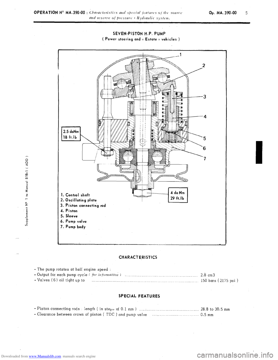
Downloaded from www.Manualslib.com manuals search engine SEVEN-PISTON H.P, PUMP
( Power steering and (( Estate )) vehicles )
1. Control shaft
2. Oscillating plate
3. Piston connectin’g rod
4. Piston
5. Sleeve
6. Pump valve
7. Pump body
CHARACTE,RISTICS
- The pump rotates at half engine speed :
- Output for each pump cycle f
/or ir/{orv/afiol; ) . . . . . . . . . . .._.._........._.........._.........._............. 2.8 cm3
- Valves (6) oil tight up to . . . . . . . . . . . . . . . . . . . . . . . . . . . . . . . . . . . . . . . . . . . . . . . . . . . . . . . . . . . . . . . . . . . . . . . .._._....... 150 bars (2175 psi )
SPECIAL FEATURES
- Piston connecting rods length ( in step of O,l mm 1 ......................................................... 28.8 to 30.5 mm
- Clearance between crown of piston ( TDC ) and pump vaIve ..... , ...................................... 0.5 mm
Page 235 of 394
Downloaded from www.Manualslib.com manuals search engine 4 OPERATION No MA. 410-00 : (haractvristirs avd special jmtms oi the irout aslc urrit REPAIRS :
- Old type (( fluid-bloc )) bushes ( length : 79.5 mm ) must not be fitted with the later wheelarms.. and vice-versa.
- It is possible, on any vehicle, to fit one, or both sides with the later wheelarms, providing the appropriate shims
are used.
Page 236 of 394
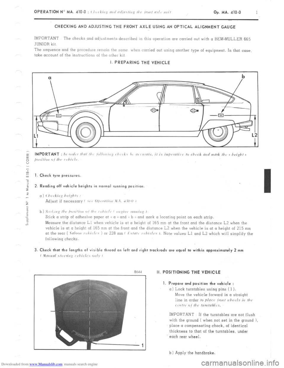
Downloaded from www.Manualslib.com manuals search engine OPERATION No MA. 410-O : ( /,c
1
CHECKING AND ADJUSTING THE FRONT AXLE USING AN OPTICAL ALIGNMENT GAUGE
IMPORTANT The checks and adjustments described in this operation are carried out with a BEM-MULLER 665
JUNIOR kit
The sequence and
the procedure remain the same when carried out using another type of equipment. In that case,
take account of the instructions of the other kit I. PREPARING THE VEHICLE
cl
b
-.
I t 1. Check tyre pressures.
2. Rending off vehicle heights in normal running position
c,)
b ) .\I ri,f,,,g /he ,w.s;‘;o,,
Measure the distance Ll when vehicle is at II height of 165 mm at the front and the distance L2 when the
vehicle is at CL height of 165 mm at the front and the distance L2 when the vehicle is at a height of 215 mm
at the rear ( .Snloo,, I vhi~/r,s 1 or 228 mm I I:.s/o/c / chirlr,. 1. Note values Ll and L2 which will simplify the
following checks. 3. Check that the lengths of visible thread on left and right trackrods are equal to within approximately 2 mm
r .Mm,,tnl 51<,<,r;r,,q I <,hirl?s WI). )
r
Rh‘td Ii. POSITIONING THE VEHIOLE
7
-1 1. Prepare and position the vehicle :
a) Lock turntables using pins ( 1 ).
Move the vehicle forward in a straight
line in order 10 plnce ironl r,hccls iv
Ihe
rwrtw o/’ fhC /,,n,tab/~s.
IMPORTANT If the turntables ore not flush
with the ground ( when not set in the ground ),
place a compensating chock, of identical
thickness to that of the turntables, under
each rear wheel.
b 1 Apply the hondbrake.
Page 241 of 394
Downloaded from www.Manualslib.com manuals search engine V. CHECKING THE ALIGNMENT OF THE FRONT WHEELS
( Front wheel toe-in )
1. Prrpnmtion oi whirlr~. Positior,
whirls. set /he s,rering 10 Ihv straight line positim~( see chapters I and II )
IMPORTANT NOTE
When the steering has been set in I( straight line >) position, (the marks in line with zero
on the sectors of the turntables
1 steering wheel and front wheels must not be touched throughout the whole of
the testing operation.
2. Check readings Ll and L2 ( see chapter I ).
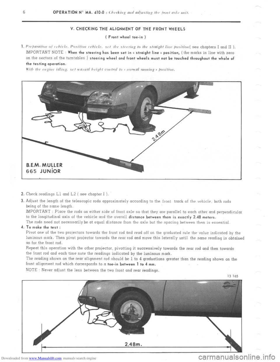
3. Adjust the length of the telescopic rods approximately according to the front track of the vehicle, both rods
being of the some length.
IMPORTANT : Place the rods on either side of front axle so that they are parallel to each other and perpendicular
to the longitudinal axis of the vehicle and the overall
distance between them is exactly 2.48 meters.
The rods need not necessarily be at equal distance from the axle but the spacing between them is essential.
4.
To make the test :
Pivot one of the two projectors towards the front rod hnd read off on the graduated rule thr value indicated by the
luminous mark. Then pivot projector towards the rear rod and move this laterally until the snne reading is obtained
as for the front rod.
Repeat this operation with the other projector, pivotting it successively towards the rear rod and then towards
the front
rod and each time note the readings indicated by the luminous mark.
The reading shown on the rem alignment rod should be 1 to 4 graduations greater than the reading shown on the
front alignment rod which corresponds to a
toe-in between 1 to 4 mm.
NOTE Never adjust the lens between the two front and rear readings.
13 165