length Citroen CX 1983 1.G Owner's Manual
[x] Cancel search | Manufacturer: CITROEN, Model Year: 1983, Model line: CX, Model: Citroen CX 1983 1.GPages: 394
Page 242 of 394
Downloaded from www.Manualslib.com manuals search engine OPERATION No MA. 410-O : I hvr-6iq n,,d od;n.s/isg /hc /~,a, nrle uei/ Op. MA. 410-O 7
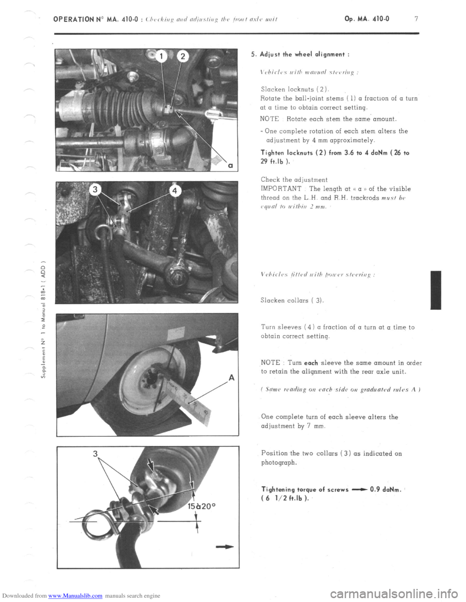
’ 15b20° 5. Adiust the wheel alignment :
\‘chirl‘,s II ilh mw,r,ol s/wrh,i: :
Slacken locknuts (2 ).
Rotate the ball-joint stems ( 1) a froctmn of a turn
at a time to obtain correct setting.
NOTE Rotate each stem the same’ amount.
- One complete rotation of each stem alters the
adjustment by 4 mm approximately. Tighten locknuts (2) from 3.6 to 4 daNm (26 to
29 ft.lb ).
Check the adjustment
IMPORTANT The length at (< a n of the visible
thread on the L.H. and R.H. trackrods ,,,r,s/ lx,
vq,,nl IO rrithin 2 ,,,7,,,
Slacken collars ( 3).
Turn sleeves (4) ~1 fraction of a turn at a time to
obtain correct setting.
NOTE Turn each
sleeve the same amount in order
to retain the oiiqnment with the rear axle unit.
I Son<, wcidisp on varh sidv o,, gmd,,lrrn/r,d rules A I
One complete turn of each sleeve alters the
adjustment by 7 mm.
Position the two collars ( 3) (IS indicated on
photograph. Ti.ghtening torque of screws - 0.9 daNm.
( 6 l/2 ft.lb ).
Page 243 of 394
Downloaded from www.Manualslib.com manuals search engine a OPERATION N’ MA. 410-O : (./~rrkiq N,,I/
VI. CHECKING AND ADJUSTING THE STEERING GEOMETRY
The crossmember supporting the steering has slots at its fixing point on the front subframe.
Any vertical movement of this crossmember alters the steering geometry.
WARNING
This operation is only to
be carried out in certain ccxses such as
-accidental impact, with repercussions on the steering system.
-work on the vehicle entoiling removal of steering crossmember.
- vehicle with poor
road stability ( p oar stright-line stability) 01 with excessive tyre weor.
CHECKING
1, Prepare the vehicle. as for checking front wheel
alignment ( Srr ~ho/,lvr
V I.
NOTE
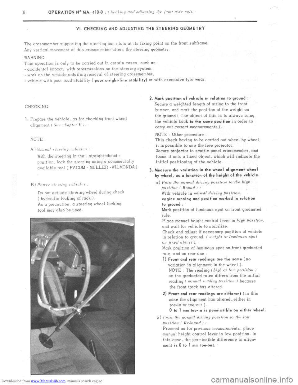
A ) \In,,unl ~fi~<,r;,,~ I chiclvs :
With the steering in the /< straightahead 1)
position. lock the steering using CI commercially
available tool ( FACOM _ MULLER -WILMONDA)
B) PO,, P)’ \,r,rr;ng r’cliirl<,.s :
Do not actuate steering wheel during check
( hydraulic locking of rock 1.
As a precaution. a steering wheel iocking
tool may also be
used. 2. Mark position of vehicle in relation to
ground :
Secure a weighted length of string to the front
bumper. and
mark the position of the weiqht on
the ground ( The
object of this is to always bring
the vehicle
bock to the some position in order to
carry out correct measurements 1.
NOTE Other procedure
This check having to be carried out wheel hy wheel.
it is possible to use the free projector.
Secure projector to scuttle panel crossmemher, and
focus it onto a fixed object, which will indicate the
initial positioning of the vehicle.
3. Measure the variation in the wheel alignment wheel
by wheel, ds o function of the height of the vehicle.
a) From Ihc m~nwnl rlri,:ir,g posi/ior, lo /hc hi@
posilio,, f ftouad 1 :
With vehicle in mwmal rlriving position.
engine running ond position marked in relation
to groond :
Mark position of luminous spot on front graduated
rule.
Place m’anual height control lever in hi&
posilirrrl.
and wait for vehicle to stabilize.
Check and adjust if necessary position of vehicle
in relation to ground. ( II
eight 01 Inmbrous spol
ou /i wd 0 hit,< I J.
Mark position of luminous spot on front graduated
rule. and on rear one
1) Front and rear readings ore the some (no
variation in alignment in the wheel 1.
NOTE : The reading f I,i$ or lorr posilios J
on the qroduated rules differs from the initial
reading f non,,nl >r,nrlinl:
position J because
the front track has altered.
2) Front and rear readings ore different ( in this
case the alignment has oltered,.either in
toe-in or toe-out ).
0 to 1 mm toe-in is permissible on either wheel
b) ,:rr ,,I, /bv IIDIINRI hi&g ,,osi,;orr lo ,I,<, lo,,
posiliov f Hrlmuad ) :
Proceed OS for previous measurements, place
manual height control lever in low position. In
this case. the permissible difference in oliqn-
ment
is O.to 1 mm toe-out.
Page 282 of 394
Downloaded from www.Manualslib.com manuals search engine OPERATION No MA. 451-O : Uwckirrg the hrflkv rov,~o,rrnts Op. MA. 451.0 1
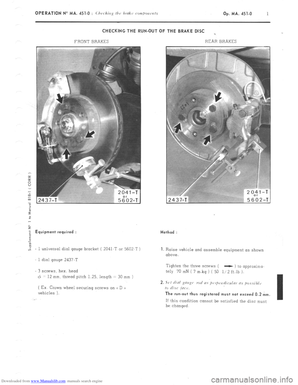
CHECKING THE RUN-OUT OF THE BRAKE DISC -
FRONT BRAKES REAR BRAKES 2
E Equipment required :
,,, - 1 universal dial gauge bracket ( 2041-T or 5602-T )
1 dial gauge 2437-T
3 screws, hex. head
6 = 12 mm, thread pitch 1.25, length = 30 mm )
( Ex Crown wheel securing screw on (< D a)
vehicles ). Method :
1. Raise vehicle and assemble equipment as shown
above.
Tighten the three screws (
- ) to opproximo
My 70 mN i 7 m.kq ) ( 50 l/2 ft.lh ).
2. .Sl,l did g”“g” rod RS pwp<‘il~cl,l171 ns p”ssibl<~
10 &SC iorr. The run-out thus registered must not exceed 0.2 mm.
If this condition cannot be satisfied the disc must
be chanqed.
Page 286 of 394
Downloaded from www.Manualslib.com manuals search engine OPERATION No MA. 454-O : Lhcckiu~ avd adjnsfbrR fhe bandbrake op. MA. 454-u I CHECKING AND ADJUSTING THE HANDBRAKE
1.
Raise front of vehicle ( wheels free ).
Remove front wheels.
Release handbrake lever to maximum extent 2. Adjust eccentrics :
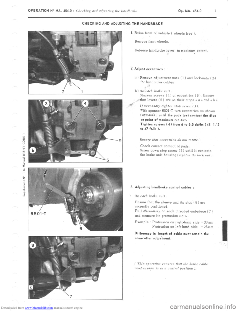
a) Remove adjustment nuts ( 1 ) and lock-nuts (2.)
for handbrake cables.
b ) O,,,‘varh hmokt~ ,,rzit :
Slacken SCI~WS (4) of eccentrics ( 6 ). Ensure
With spanner 6501-T turn eccentrics as shown f rrpu,ards ) until the pads just contact the disc
at point of maximum run-out.
Tighten screws (4) from 6 to 6.5 daNm (43 l/2
to 47 ft.lb ).
Check correct contact of pads.
Screw down stop SCI~W (3) until it contacts
the brake unit housing ( tighfrn its lock EN! 1, 3. Adjusting hondbrake control cables :
, On rnrh hrnkc ,,,, if:
Ensure
Pull alfcmnf~~iy on each threaded end-piece (7 )
ond measure its protrusion (< c 1).
.Example : Protrusion on right-hand side = 30 mm
Protrusion on left-hand side = 26mm Difference in length of cable must remain the
some after adiuitment.
Page 348 of 394
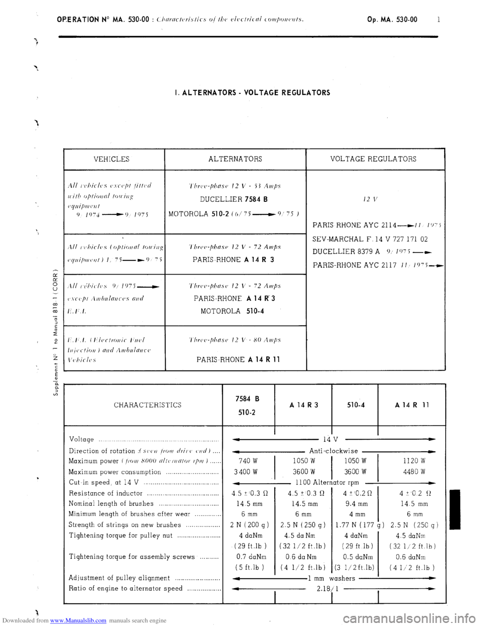
Downloaded from www.Manualslib.com manuals search engine OP,ERATlON No MA. 530-00 : <.Ilnrnctc,rislics oj I/IV cJlec/rical cor~~/~~r~c~~t/s. Op. MA. 530-00 1 I. ALTERNATORS - VOLTAGE REGULATORS
VEHICLES ALTERNATORS VOLTAGE REGULATORS
1111 r~c,hicl(~s CJ.\~(J/)/ /il/ocJ ‘l’hrc~c~-pilasc~ 12 v - 53 .4r,/ps
ri.ilh f~/~IioI~oI lo/i irjg DUCELLIER 7584 B 12 v c~yuipmc~ril
0 1 !, 74 - 0 I 97 i
MOTOHOLA 51 O-2 C o/ 75 __t 0 ’ ‘5 )
PARIS RHONE AYC 2114 -11 I’)‘5
SEV-MARCHAL F, 14 V 727 171 02
/Ill I c)hiclvs (opliotfni lowirtg ‘l’hre~~-phase 12 V - 72 Amps
DUCELLIER 8379 A 0; 107 5 --
~~yui/mc,,fl J I, 7i-*9 7i PARIS-RHONE A 14 R 3 PARIS-RHONE AYC 2117 II/ 1(j75-t
Three-phase’ 12 V - 72 Amps
PARIS-RHONE A 14 R 3
MOTOROLA 510-4
Thr~~~~-pha.s~~ 12 V - 80 /lt)t/?s
PARISRHONE A 14 R 11
7584 B CHARACTERISTICS A14R3 51 o-4 A 14 R 11
51
O-2
Voltage .._._._.._._.._____.......................,...................,. -
14 v w
Direction of rotation :f s(‘(‘I/ /rot)/
rlril C’ C,I/C/ J
- Anti-clockwise
Maximum power f /X),/I S1)OO
~/I/c,~/IN/oI. r/j/u ) ..,__, 740 w 1050 w 1050 w 1120 w
Maximum power consumption . . . . . .._..__.______........
3400 w 3600 W 3600 W 4480 W
Cut -in speed, at 14 V . .
4 1100 Alternator rpm t
Resistance of inductor . .
4 5 Z’O.3 cl 4.5 ? 0.3 Q 4 k’O.2 0 4 +,o 2 12
Nominal length of brushes .
14.5 mm 14.5 mm 9.4 mm 14.5 mm
Minimum length of brushes after wear . . 6 mm 6 mm 4 mm 6 mm
Strength of strings on new brushes . . . . . . . . . . . . . . . . . 2 N ( 200 g ) 2.5 N (250 g)
1.77 N (177 g) 2.5 N (250 g)
Tightening torque for pulley nut . . 4 daNm 4.5 da Nm 4 daNm
4.5 daNm
(29 ft.lb ) (32 l/2 ft.lb) ( 29 ft .lb ) (32 l/2 ft.lb)
Tightening torque for assembly screws .
0.7 daNm 0.6 da Nm 0.5 daNm 0.6 daNm
(5 ft.lb ) (4 l/2 ft.lb
j (3 1,‘2ft.lb) (4 1/‘2 ft.lb )
Adjustment of pulley alignment . . . . . . . . . . . . . . . . . . . . . . . . 4
1 mm washers w
Ratio of engine to alternator speed . . . 4
2.18/ 1 *
I I
Page 351 of 394
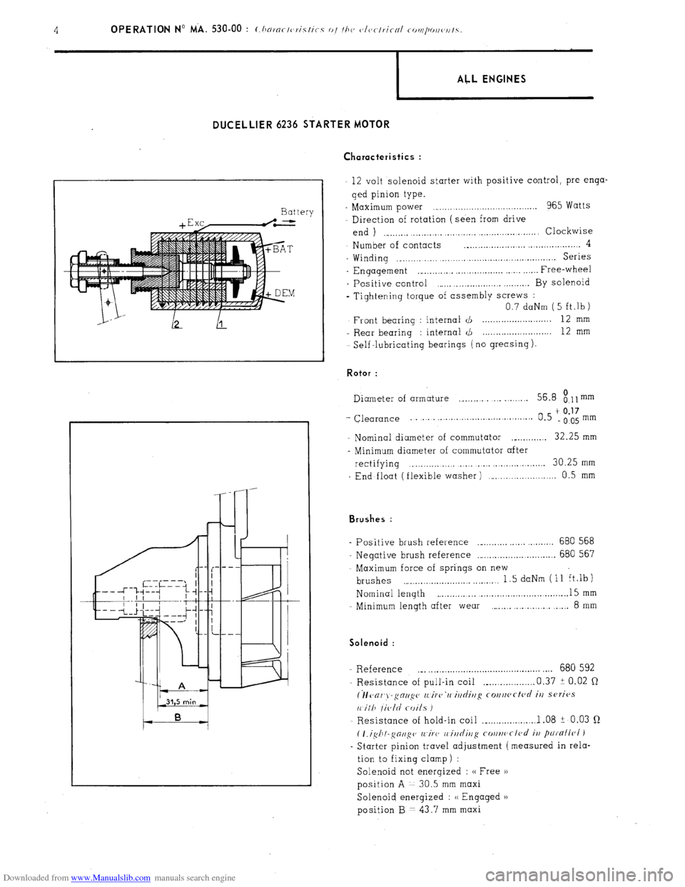
Downloaded from www.Manualslib.com manuals search engine DIJCELLIER 6236 STARTER MOTOR
Ch aracteristics :
Battery
+ E xc,-.L
I ALL ENGINES
12 volt solenoid starter with positive control, pre-enga-
ged pinion type.
- Maximum power ,.,..................................... 965 Watts
Direction of rotation (seen from drive
end ) ,.,_,.,.,. ..,.,...,.,. ,.,.,.,...._ . . . . .._...... .,.,. Clockwise
Number of contacts ._.,.,.,.,.,.,_........ ..,.,.,............. 4
- Winding ._.,.,......... ,.,.,.,_......,.,.....,.,...............~... Series
- Engagement ,~.,.,...,... ,.,............... . Free-wheel
- Positive control ,.,.,. . . . . . . . . . . ..,.,.,... By solenoid
- Tightening torque of assembly screws :
0.7 daNm ( 5 ft,lb)
Front bearing : internal d . . . 12 mm
- Rear bearing : internal <,!J 12
mm
Self -lubricating bearings ( no greasing ). Rotor :
Diameter of armature ,_,.,.,. .,. _..._.... 56.8
8.11 mm
‘- Clearance ... . . . . . . . . . . . .
t 0.17 0.5 e005mm
- Nominal diameter of commutator ._._...,.,.,. 32.25 mm
- Minimum diameter of commutator after
rectifying . . . . . . . . . . . . . . . . . . . . . 30.25 mm
End float (flexible washer) ,.........,.,.,..._.....,. 0.5 mm Brushes :
Positive brush reference ._._.,.,... ,..... . . . . . 680 568
Negative brush reference ..,.,.,.,.,.,.,............... 680 567
Maximum force of springs on new
brushes . . . . . . . . . . . . . . . . . . . . . . . . . . . . . 1.5 daNm (11 ft.lb)
Nominal length . . . . ._.............,...............~. 15 mm
Minimum length after wear ., . . . . . . . . 8
mm Solenoid :
- Reference ._. ,.,..............~........................ .,.. 680 592
Resistance of pull-in coil ,_...,.,.........,. 0.37 i 0.02 Q
(lfc~or~j-gctup (L irc~‘rc iltdittg co~~rtcftc~d it/ series
11 ill7 /ic,ld coils I
Resistance of hold-in coil ,_...,...,.......... 1 .08 ? 0.03 Q
( I.igh!-~oll~c~ /l~iF(, I, ittditlg cottrtc~cl<~d
it/ parnllr~l )
- Starter pinion travel adjustment (measured in rela-
tion to fixing clamp) :
Solenoid not energized : (( Free H
position A 30.5 mm maxi
Solenoid energized : u Engaged u
position B 7 43.7 mm maxi
Page 352 of 394
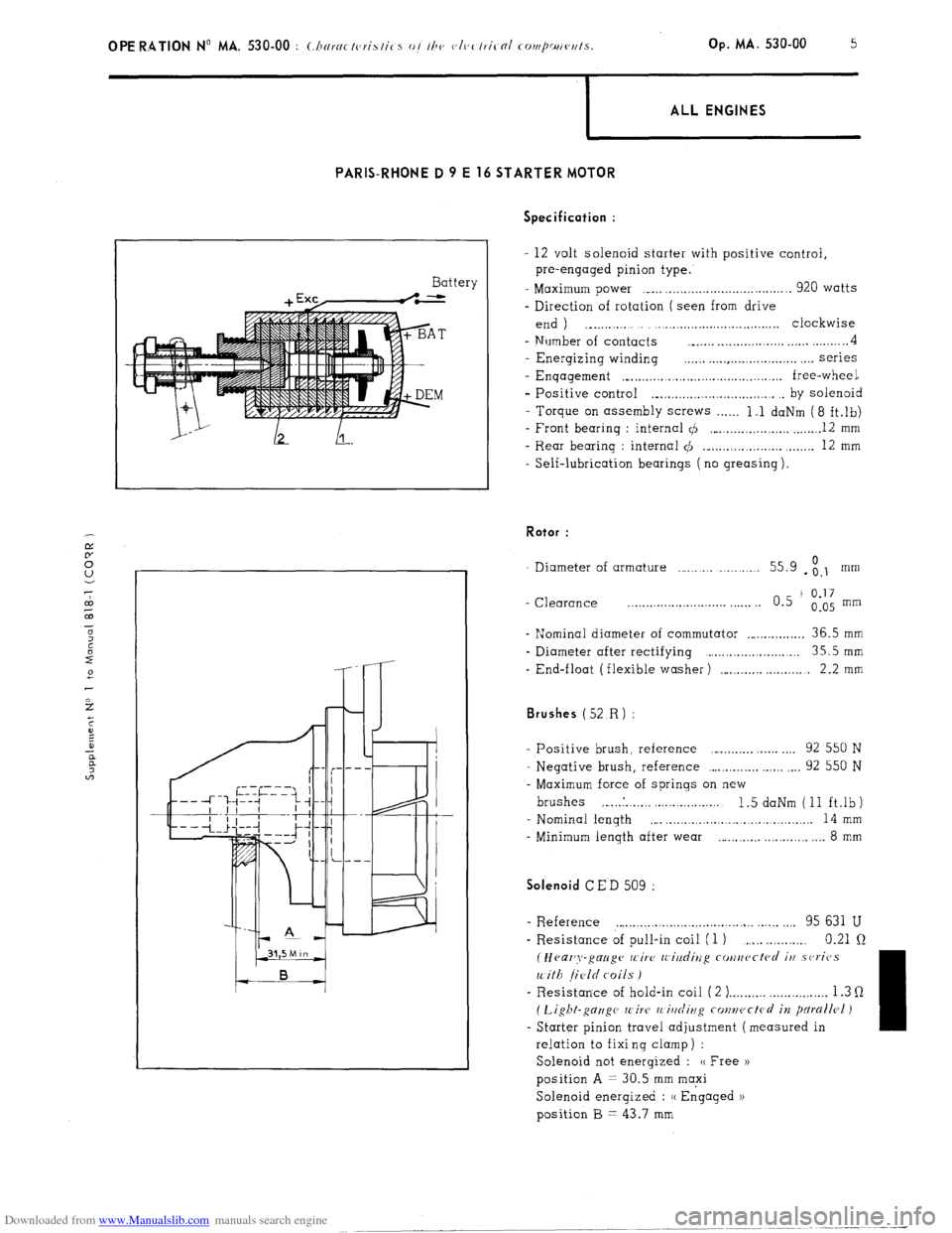
Downloaded from www.Manualslib.com manuals search engine 1 ALL ENGINES
PARIS-RHONE D 9 E 16 STARTER MOTOR
Battery Specification :
- 12 volt solenoid starter with positive control,
pre-engaged pinion type.
- Maximum power ,..... ,................................. 920 watts
- Direction of rotation ( seen from drive
end ) ., . . . ._..,.,...,.,..................... clockwise
- Number of contacts __..... . . . . . . . . . . . . . . . . . . . . . . . . . . . 4
- Energizing winding . . . . . . . . . . . . . . . . . . . . . . . . . . . . . . . . . . series
- Enqagement ,“...,.,.........,.,.............,......... free-wheel
- Positive control ._.,.,.,.,.,.,.......,.,.,....... . by solenoid
- Torque on assembly screws . . . . . . 1.1 daNm (8 ft.lb)
- Front bearing : internal 4 ,..._.,.....,...,.,.,. _....._. 12 mm
- Rear bearing : internal $I ._...,...,...,.,.,.,. ,.....,. 12 mm
- Self-lubrication bearings ( no greasing ). Rotor :
Diameter of armature . . . . . . . . . . . . . . . 55.9 - ;.I mm
- Clearance _.......................... . . . . . . 0.5 ’
0.17
0.05 mm
- “Jominal diameter of commutator . . . . . . . . . . . . . . . . 36.5 mm
- Diameter after rectifying ,.....,................... 35.5mm
- End-float (flexible washer) ,....._.,... . . . 2.2 mm Brushes (52
R) :
- Positive brush, reference . . . . . . . . . . . . . . 92 550 N
- Negative brush, reference ,...,.,.,.,.,. ,.,.,. . . . 92 550 N
- Maximum force of springs on new
brushes ,... ..I. . ,. ,. . . . ..,......... 1.5 daNm (11 ft.lb)
- Nominal length
,... . . . . . . .., . . . . . . . .,......... 14 mm
- Minimum length after wear . . . . . . . ..,......... 8 mm Solenoid
CED 509 :
- R.eference . . . . . . . . . . . . . . . . . . . . . . . . . . . . . . . . . . . . . . . ,.,. 95 631 U
- Resistance of pull-in coil (1 ) . . . . . 0.21 Q
(Heaz’y-gauge wire IL’i?/dirzg cotlucctcd iu .sc,ricJs
with field coils )
- Resistance of hold-in coil ( 2 ) . . . . . . . . . . . . . . . . . . . . . . . . . . 1.3 Q
( Light-gc7zigc wire’ 11 itlrliug conwctcrl in pdrallrl )
- Starter pinion travel adjustment (measured in
relation to fixi ng clamp ) :
Solenoid not energized : (( Free ))
position A = 30.5 mm maxi
Solenoid energized : (( Engaged 1)
position B = 43.7 mm
Page 359 of 394
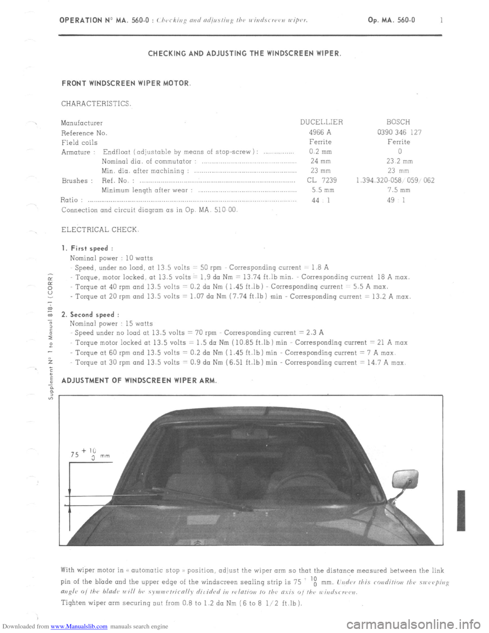
Downloaded from www.Manualslib.com manuals search engine OPERATION No MA. 560.0 : ~hrrkin~ o,,d oc/@s/i,,g I/><, wiurisrrrr,, wip’r. Op. MA. 560.0
1
Fi
m
0 CHECKING AND ADJUSTING THE WINDSCREEN WIPER.
FRONT WINDSCREEN WIPER MOTOR
CHARACTERISTICS.
Manufacturer DUCELLIER
Reference No. 4966 A
Field coils Ferrite
Armature : Endfloot (adjustable by means of stop-screw) : 0.2 mm
Nominal dia. of commutator :
24 mm
Min. dia. after machining : 23 mm
Brushes : Ref. No. :
CL 7239
Minimum length after wear : 5.5 mm
Ratio : .._...................................................................................................
44 1
Connection and circuit diagram as in Op. MA. 510 00.
ELECTRICAL CHECK. BOSCH
0390 346 127
Ferrite
0
23.2 mm
23 mm
1.394.320-058 059, 062
7.5 mm
49 1
1. First speed :
Nominal power : IO watts
Speed, under no load, at 13.5 volts = 50 rpm Corresponding current = I.8 A
Torque, motor locked, at 13.5 volts = 1.9 da Nm 7 13.74 ft.lb min. Corresponding current 18 A max.
Torque at 40 rpm and 13.5 volts = 0.2 do Nm (1.45 ft.lb) Correspondinq current = 5.5 A max.
- Torque ot 20 rpm and 13.5 volts = 1.07 da Nm (7.74 ft.lb) min Corresponding current = 13.2 A max.
2. Second speed :
Nominal power : 15 watts
Speed under no load at 13.5 volts = 70 rpm Corresponding current = 2.3 A
Torque motor locked at 13.5 volts = 1.5 do Nm (IO.85 ft.lb) min Corresponding current = 21 A max
Torque at 60 rpm and 13.5 volts = 0.2 da Nm (1.45 ft.lb) min Corresponding current = 7 A max
Torque ot 30 rpm and 13.5 volts = 0.9 da Nm (6.51 ft.lb) min Corresponding current = 14.7 A mrx.
ADJUSTMENT OF WINDSCREEN WIPER ARM
With wiper motor in (< automatic stop )/ position, adjust the wiper arm so that the distance measured between the link
pin of the blade and the upper edge of the windscreen sealing strip is 75 ‘t
mm. L’vd‘ar /his rondiliw, /he 51, rvp;,,g
m,g/r 0, /he bladr ,,~i// hv symv,r~/rirn//v dil idrd it, w/n/io,, 10 /he O.YiS “, I/w r,‘iri
Tighten wiper arm securing out from 0.8 to 1.2 da Nm (6 to 8 l/2 ft.lb).
Page 360 of 394
Downloaded from www.Manualslib.com manuals search engine 2 OPERATION No MA. 560-O : (:/ ivc ,,,* our/ nd;,,s/ii,~ ,,w I, ,,i
k’
REAR WINDSCREEN WIPER MOTOR (lislnlvs J
CHARACTERISTICS.
Mon”facturer ..,..._....,...........,.................................................................................................... BOSCH
~ef,yence
~0. . . . . . . . . . . . . . . . . . . . . . . . . . . . . . . . . . . . . . . . . . . . . . . . . . . . . . . . . . . . . . . . . . . . . . . . . . . . . . . . . . . . . . . . . . . . . . . . . . . . . . . . . . . . . . . . . . . . . . . . . .... WXP
12 V 0390
526 071
Field Coils
. . . . . . . . . . . . . . . . . .._............................................................................................................ Ferrite
Armature :
Endfloat ( “ot adj”stable ) . . . . . . . . . . . . . . . . . . . . . . . . . . . . . . . . . . . . . . . . . . . . . . . . . . . from 0.05 to 1 2 mm
Nominal diameter of commutator . . . . . . . . . . . . . . . . . . . . . . . . . . . . . . . . . . . . . . . . . . . . . . . . . . . . . . . . . 13 mm
Minimum diameter after machining . . . . . . . . . . . . . . . . . . . . . . . . . . . . . . . . . . . . . . . . . . . . . . . . . . . . . . 12 mm
Brushes :
&ference
No. ,.: . . . . . . . . . . . . . . . . . .._.................................................................................
Minimum length after wear ,.,......._................,...................................................... 3 mm ( wear of 5.5 mm )
Ratio :
. . . . . . . . . . . . . . . . . . . . . . . . . . . . . . . . . . . . . . . . . . . . . . . . . . . . . . . . . . . . . . . . . . . . . . . . . . . . . . . . . . . . . . . . . . . . . . . . . . . . . . . . . . . . . . . . . . . . . . . . ................ 1 90.7
Tightening torque of fixing nut of wiper motor .,.....,..,................................................~.......... 1 to 1.5 da Nm
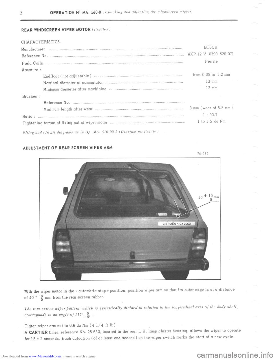
H/;r;,,p nj,d c;K,J;, djogmms 0.5 in O/j. .\1,2. i10-00 h Il)ing:rtirn Ior lirl0l~~ ) ADJUSTMENT OF REAR SCREEN WIPER ARM.
n
Tigtenwiperarm nut to0.6daNm (4 l/4 ft.lb).
A CARTIER
timer, reference No. 25 630, located in the IMT L.H. lamp cluster housihg, allows the wiper to operate
for 15 ? ‘2 seconds. Each actuation (of at least one second ) on the wiper switch marks the start of (I new cycle
Page 378 of 394
Downloaded from www.Manualslib.com manuals search engine OPERATION No MA. 642-W : ~Thnracteristics o/ thy, e I:Ko/I) - -70 3 hc,nriug s, stew Op. MA. 642-00 3
When starting : capsule is subjected to vacuum
Vacuum capsule
Westaflex tube
c J
J
COLD AIR
Closing plate for
SUPPLY SHUT OFF warm air supply
,
Flap B
I
to air filter
DIAGRAM.No. 1
‘acuum capsule not under vacuum
Flap
DIAGRAM No. 2
to air filter
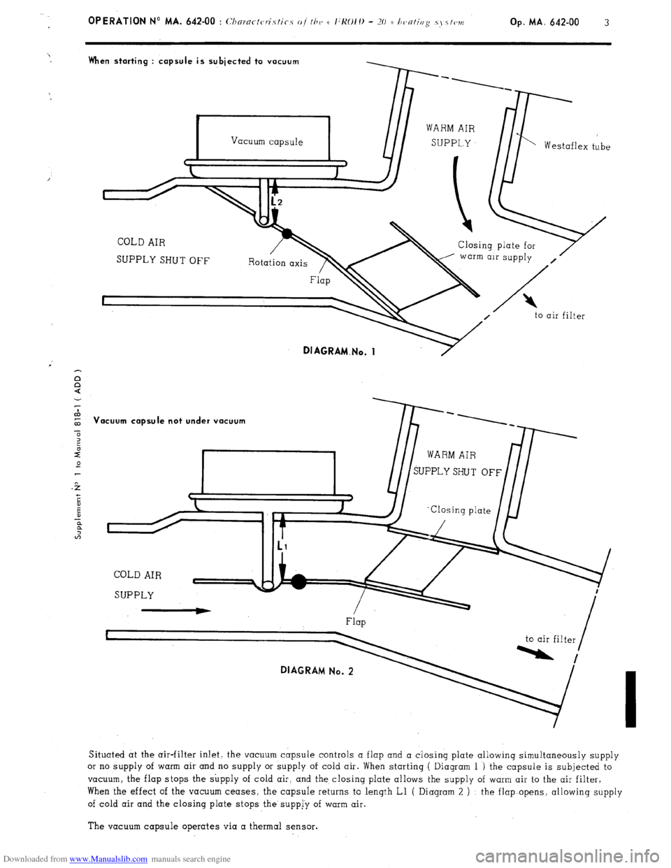
Situated at the air-filter inlet. the vacuum capsule controls a flap and a closing plate allowing simultaneously supply
or no supply of warm air and no supply or supply of cold air. When starting ( Diagram 1 ) the capsule is subjected to
vacuum, the flap stops the supply of cold air, and the closing plate allows the supply of warm air to the air filter.
When the effect of the vacuum ceases, the capsule returns to length Ll ( Diagram 2 ) : the flap.opens, allowing supply
of cold air and the closing plate stops the supp[y of warm air.
The vacuum capsule operates via a thermal sensor.