torque Citroen CX 1983 1.G User Guide
[x] Cancel search | Manufacturer: CITROEN, Model Year: 1983, Model line: CX, Model: Citroen CX 1983 1.GPages: 394
Page 52 of 394
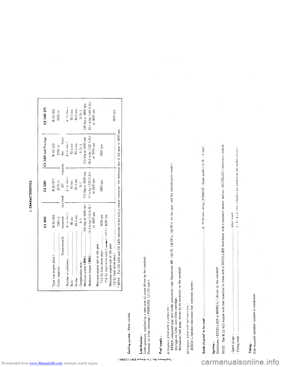
Downloaded from www.Manualslib.com manuals search engine I. CHARACTERISTICS
:
0
u
5 Cooling system : Water cooled.
z
T cx 2000 cx 2200 CX 2400 and Prestige
CX 2400 GTI
- Type ( on engine p’late ) : _..._................... M 20/616 M 22/617 M 23/ 623
M 23/622
Cubic capacity : . . .._......_...............
1985 cc 2175 cc 2350 cc 2350 cc
Transversely mounted, inclined
300 towards the front
Number of cylinders : _........................... 4 (iI/ linr, J 4 Iin linr,)
4 (irr /iUP J 4 f in lin i’ ,
Bore : 86 mm 90 mm 93.5 mm 93.5 mm
- Stroke : .,.,,_,.,.,....____.,.. .._._.....................
85.5 mm 85.5 mm 85.5 mm
85.5 mm
Compression ratio :
9/I 9/l 8.7511 8.7511
Maximum power ( DIN ) : . . . .._................... 102 bhp at 5500 rpm 112 bhp at 5500 rpm 115 bhp ot 5500 rpm
128 bhp at 4800 rpm
Maximum torque (DIN)
: . . 15.5 m.kg (112 ft.Ib ) 17 m.kq (123 ft.Ib) 18.2 m.kg ( 132 ft.Ib)
20.1 mkq (145 ft.Ib)
at 3000 rpm at 3500 rpm at 3000 rpm
at 3600 rpm
Maximum engine rpm in 4th gear :
* 13/62 final drive rtrtio :
5600 rpm 5800 rpm 5900 rpm
*14/61 final drive ratio ( -1 1’175 J 4600 rpm
Maximum engine rpm in 5th gear
(
13,‘62 final drive ratio ) : ,._............,..,........,....,.,........,..,.,..... .._.........,................ .._..._...................
5600 rpm
* NOTE : For CX 2200 and CX 2400 vehicles fitted with a torque converter, the maximum rpm in 3rd gear is 5600 rpm.
: Lubrification :
i
Under pressure, supplied by o gear-type oil-pump driven by the camshaft.
2
External oil filter cartridge ( PURFLUX, LS 105 type ).
d
z
;
i Fuel supply :
a
i a) Engines fitted u~ifh a rnrbuwffor
WEBER compound-type twin choke carburettor (s.ee Operations MA. 142-00, 142-00 a, 142-00 b far the type, and the identification marks )
Dry-type air filter, with filter cartridge.
Mechanical fuel pump, driven by on eccentric on the camshaft.
b) i?ugi,jes ji/f.rd II ith /LIP/ iniPr/ioo :
BOSCH L-Jetronic electronic fuel injection system
Grade of pet,ol to be used : > ._,,,,.,_.._,,,,,.,......... . .._...o....._............................................. K.
99 Orrani ralrrig (FRANCE : Super grade ) (U.K. : 4-star )
Ignition :
Distributor ( DUCELLIER or MARELLI ) driven by the camshaft.
NOTE : The M 23/622 engine with fuel injection is fitted with (I DUCELLIER distributor with a magnetic sensor, and an u AC-DELCO /a electronic module.
- Spark pluqs : .................................................................................................................................... shorf warh
Firing o&r : .................................................................................................................................... 1 - 3 - 4 - 2 f tbu cylinders ale INR&Cd 011 the roc6w COI rr,
Timing :
Side mounted camshaft located in crankcase.
Page 55 of 394
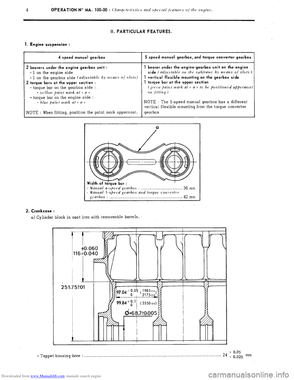
Downloaded from www.Manualslib.com manuals search engine 4 OPERATION No MA. 100-00 : ChargctrJristics and special jeattlws of the engine. II. PARTICULAR FEATURES.
1. Engine sugpension :
4 speed manual gearbox
2 bearers under the engine gearbox unit :
- 1 on the engine side
- 1 on the gearbox side (adjustable by means o/ slots)
2 torque bars at the upper section :
- torque bar on the gearbox side :
- yellow paint mark at (( a ))
- torque bar on the engine side :
- blue paint mark at (( a ))
NOTE : When fitting, position the paint mark uppermost.
5 speed manual gearbox, and torque converter gearbox
bearer under the engine-gearbox unit on the engine
side
(adirrstable OH the subjranra by means oj slots)
vertical flexible mounting on the gearbox side
torque bar at the upper se‘ction
(green paint mark at CC a n to be positioned uppermost
072 jittiug )
NOTE : The 5-speed manual gearbox has a different
vertical flexible mounting from the torque converter
gearbox
a
- Mat7~ral gearbox : . . . . . . . . . . . . . . . . . . . . . . . . . . . . . . . . . . . . 36 mm - Manual S-speed gc,arbox and torque cowrvrtcr gearbox : . . . . . . . . . . . . . . . . . . . . . . . . . . . . . . . . . . . . . . . . . . . . . . . . . . . . . . . . . . . . . . . . 42 mm 2. Crankcase :
a) Cylinder block in oast iron with removeable barrels.
+ 0.05 - Tappet housing bore : . . . . . . . . . . . . . . . . . . . . . . . . . . . . . . . . . . . . . . . . . . . . . . . . . . . . . . . . . . . . . . . . . . . . ..~.................................................
24 + 0.025 mm
Page 57 of 394
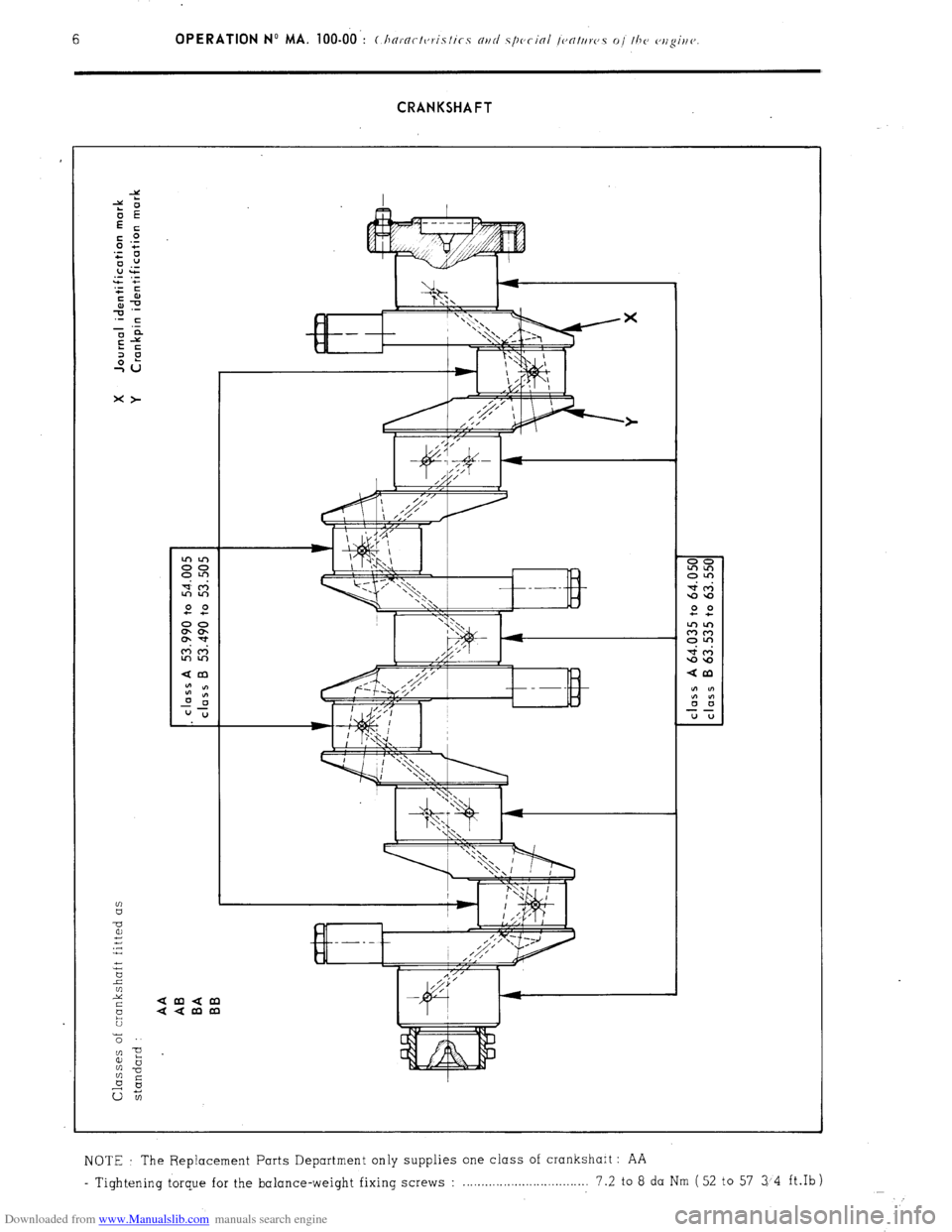
Downloaded from www.Manualslib.com manuals search engine CRANKSHAFT
?c
2
2 amam
aamm
t;
z
NOTE The Replacement Parts Department only supplies one class of crankshaft : AA
- Tight.ening torque for the balance-weight fixing screws : 7.2 to 8 da Nm (52 to 57 34 ft.Ib)
Page 58 of 394
Downloaded from www.Manualslib.com manuals search engine Op. MA. 100-00 7
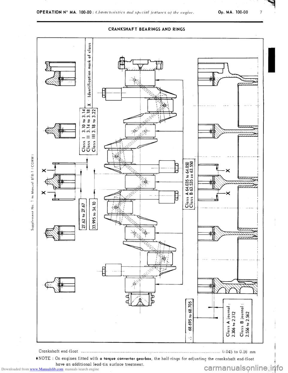
CRANKSHAFT BEARINGS AND RINGS
Crankshaft end-float . . . . . . . . . . . . . . . . . . . . . . . . . . . . . . . . . . . . . . . . . . . . . . . . . . . . . . . . . . . . . . . . . . . . . . . . . . . . . . . . . . . . . . . . . . . . . . . . . . . . . . . . . . . . . . . . . . . . . . . . .....
b.045 to 0.16 mm
+NOTE : On engines fitted with a torque converter gearbox,
the half-rings for adjusting the crankshaft end-float
have an additional lead-tin surface treatment.
Page 63 of 394
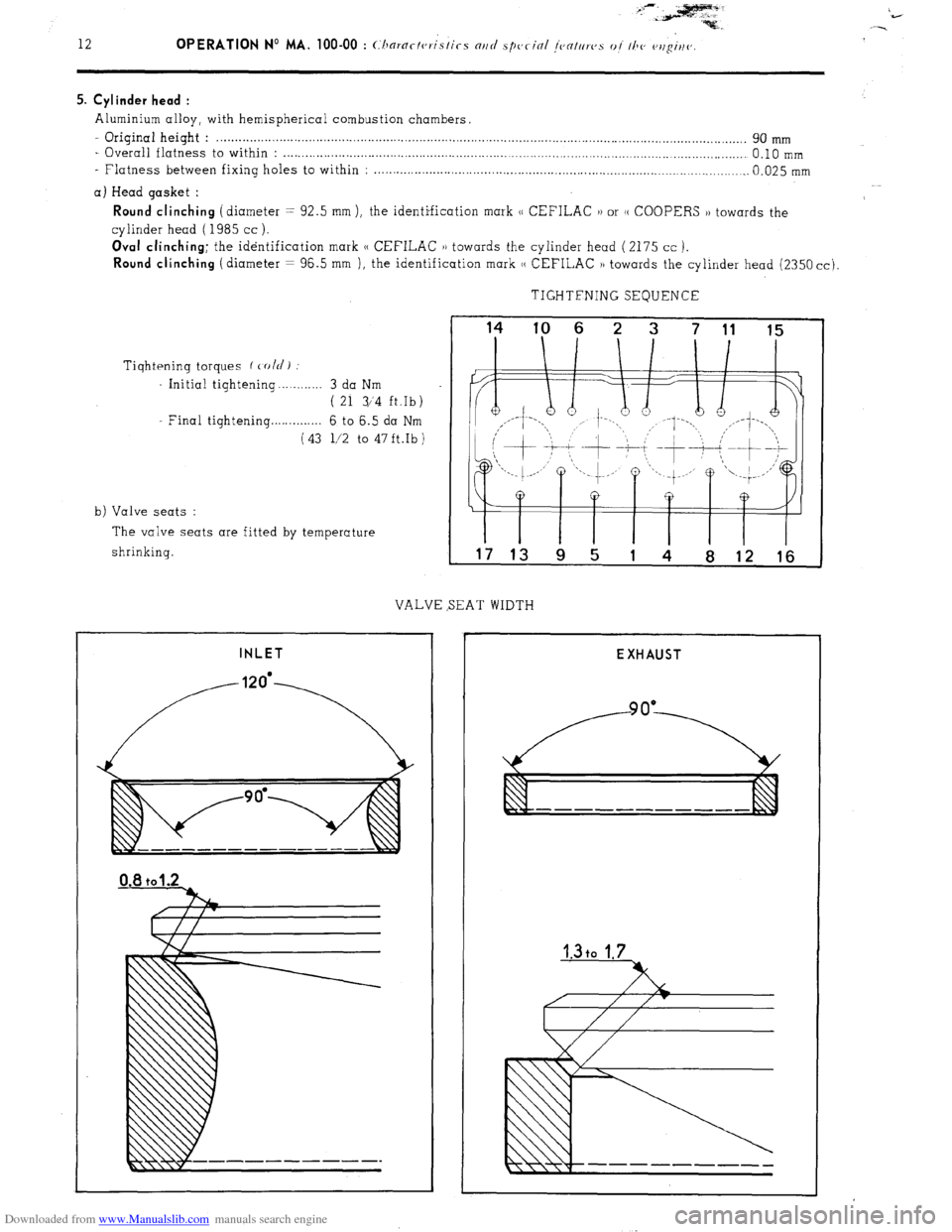
Downloaded from www.Manualslib.com manuals search engine 5. Cylinder head :
Aluminium alloy, with hemispherical combustion chambers.
- Original height : . . . . . . . . . . . . . . . . . . . . . . . . . . . . . . . . . . . . . . . . . . . . . . . . . . . . . . . . . . . . . . . . . . . . . . . . . . . . . . . . . . . . . . . . . . . . . . . . . . . . . . . . . . . . . . . . . . . . . . . . ........................ 90 mm
- Overall flatness to within : . . . . . . . . . . . . . . . . . . . . . . . . . . . . . . . . . . . . . . . . . . . . . . . . . . . . . . . . . . . . . . . . . . . . . . . . . . . . . . . . . . . . . . . . . . . . . . . . . . . . . . . . . . . . . . . . . . . . . . . . ...... 0.10 mm
- Flatness between fixing holes to within : . . . . . . . . . . . . . . . . . . . . . . . . . . . . . . . . . . . . . . . . . . . . . . . . . . . . . . . . . . . . . . . . . . . . . . . . . . . . . . . . . . . . . . . . . . . . . . . . . . . . . 0.025 mm
a) Head gasket :
Round clinching (diameter = 92.5 mm ), the identification mark (( CEFILAC 1) or (( COOPERS )) towards the
cylinder head ( 1985 cc ).
Oval clinching; the identification mark (( CEFILAC 1) towards the cylinder head (2175 cc ).
Round clinching (diameter = 96.5 mm ), the identification mark (( CEFILAC )) towards the cylinder head (2350 cc).
TIGHTFNING SEQUENCE
Tiqhtening torques f cold)
Initial tightening . . . . . . . . . . 3 da Nm
( 21 3/‘4 ft.Ib)
Final tightening . . . . . . . . . . . . . 6 to 6.5 da Nm
(43 l/2 to 47ft.Ib)
b) Valve seats :
The valve seats are fitted by temperature
shrinking.
VALVE SEAT WIDTH
INLET
I I I I I I T
17 13 9 5 1 4 8 12 16
EXHAUST
Page 68 of 394
Downloaded from www.Manualslib.com manuals search engine OPERATION No MA. 100-00 : Characteristics and special jeafruvs oj the cvlghv.
Op. MA. 100-00 17
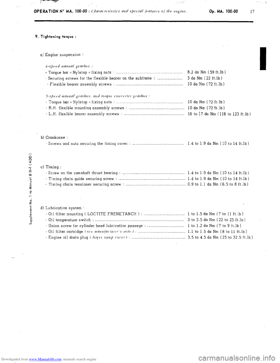
9..Tightening torque :
a) Engine suspension :
4-.spc~~d manrlal gearbox :
7 Torque bar (( Nylstop )) fixing nuts : .............................................................. 8.2 da Nm ( 59 ft.Ib )
- Securing screws for the flexible bearer on the subframe ; ........................ 3 da Nm ( 22 ft.lb)
- Flexible bearer assembly screws :
..................................................... .
........ 10 da Nm (72 ft.lb)
S-sp~~tl n1m11ra1 gca~box. and forq~~c cour,c~rtrr gc~arkos
- Torque bar (( Nylstop )) fixing nuts : . . . . . . . . . . . . . . . . . . . . . . . . . . . . . . . . . . . . . . . . . . . . . . . . . . . . . . . . . . . . . . 10 da Nm (72 ft.lb)
- R:H. flexible mountinq assembly screws : . . . . . . . . . . . . . . . . . . . . . . . . . . . . . . . . . . . . . . . . . . . . . . . . . . . . 10 da Nm ( 72 ‘ft.lb )
- L.H. flexible bearer assembly screws : . . . . . . . . . . . . . . . . . . . . . . . . . . . . . . . . . . . . . . . . . . . . . . . . . . . . . . . . 16 to 17 da Nm ( 116 to 123 ft.lb )
b) Crankcase :
Screws and nuts securing the timing cover : . . . . . . . . . . . . . . . . . . . . . . . . . . . . . . . . . . . . . . . . . . . . . . 1.4 to 1.9 da Nm (10 to 14 ft.lb)
c) Timing :
- Screw on the camshaft thrust bearing : . . . . . . . . . . . .._............................................ 1 .4 to 1 .9 da Nm ( 10 to 14 ft.lb )
- Timing chain guide securing screw : . . . . . . . . . . . ..__................................ . . . . . . . . . . . . . . .
1.4 to 1.9 da Nm ( 10 to 14 ft.lb)
- Timing chain tensioner securing screw : . . . . . . . . . . . . . . . . . . . . . . . . . . . . . . . . . . . . . . . . . . . . . . . . . . . . . . . 0.9 to 1 .I da Nm (6.5 to 8 ft.lb )
d) Lubrication system :
- Oil filter mounting ( LOCTITE FRENETANCH ) : ......................................
1 to 1 .5 da Nm ( 7 to 11 ft.lb )
- Oil temperature switch : .................................................................................. 3 to 3.5 da Nm ( 22 to 25 ft.lb )
- Union screw for cylinder head lubrication passage : ..................................
1 to 1 .2 da Nm ( 7 to 9 ft.lb )
- Oil filter cartridge ( SPV
wnrt/r]nctc/rer‘s rmte ) : ............................................ 1 .l to 1 .5 da Nm ( 8 to 11 ft.lb )
- Engine oil drain plug ( lo~!,c,r s/t~/p
co/‘cr) : .................................................. 3.5 to 4.5 da Nm (25 to 32.5 ft.lb)
Page 69 of 394
Downloaded from www.Manualslib.com manuals search engine OPERATION No MA. 112-O : ChcJcking and adjusting the valrv mechanism. Op. MA. 112-O
1
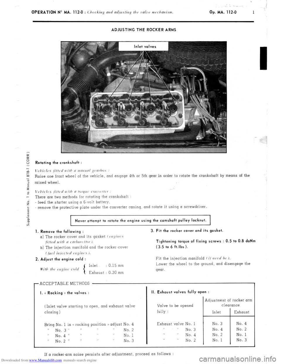
ADJUSTING THE ROCKER ARMS
Ir
E
2 Rotating the crankshaft :
7
m
Vc,birlvs /i//cd wifh n WRIINRI ~varbot :
E Raise one front wheel of the vehicle,
and engage 4th or 5th gear in order to rotate the crankshaft by means of the
3
6 raised wheel.
I
e Vchirlcs /ittcd wilh a lo~qnr covwrlc~ :
- There are two methods for rotating the crankshaft :
Gz feed the
starter using CI G-volt battery,
;
remove the protective plate under the converter casing, and rotate it using a screwdriver.
:
Never attempt to rotate the engine using the camshaft pulley locknut.
1. Remove the following :
a) The rocker cover and its gasket (~,ofii~rr~s
/i//d Will, a rarb,,wt/or I.
b) The injection manifold and the racker-cover
(/,,<,I iU/<~CfPd r,zgir,rs 1.
2. Adiust the engine cold :
Inkt : 0.15 mm
With lb<‘
3. Fit the rocker cover and its gasket.
Tightening torque of fixing screws : 0.5 to 0.8 daNm
(3.5 tc. 6 ft.lbs ).
Fit the injection manifold f i/ nczvd br 1.
Lower the wheel to the ground,
and disengage the
gear.
r ACCEPTABLEMETHODS
I I
I. (< Rocking )> the valves :
(Inlet valve starting to open, and exhaust valve
I
closing) closing)
Bring No. 1 in <, rocking position /) adjust No. 4 Bring No. 1 in <, rocking position /) adjust No. 4
II II
No. 3” ” ” ” No. 3” ” ” ” No. 2 No. 2
0 0
No.4 I’ ” ” ” No.4 I’ ” ” ” No. 1 No. 1
” No.2 ” ” ” ” ” No.2 ” ” ” ” No. 3 No. 3
II. Exhaust valves fully open :
Valve to be opened
fully : Adjustment of rocker arm
CleUKUlCe
Exhaust valve No. 1
,, I, No. 3
,, ,, No. 4
,, ,, No. 2
If a rocker-rim noise persists after adjustment, proceed as follows :
Page 70 of 394
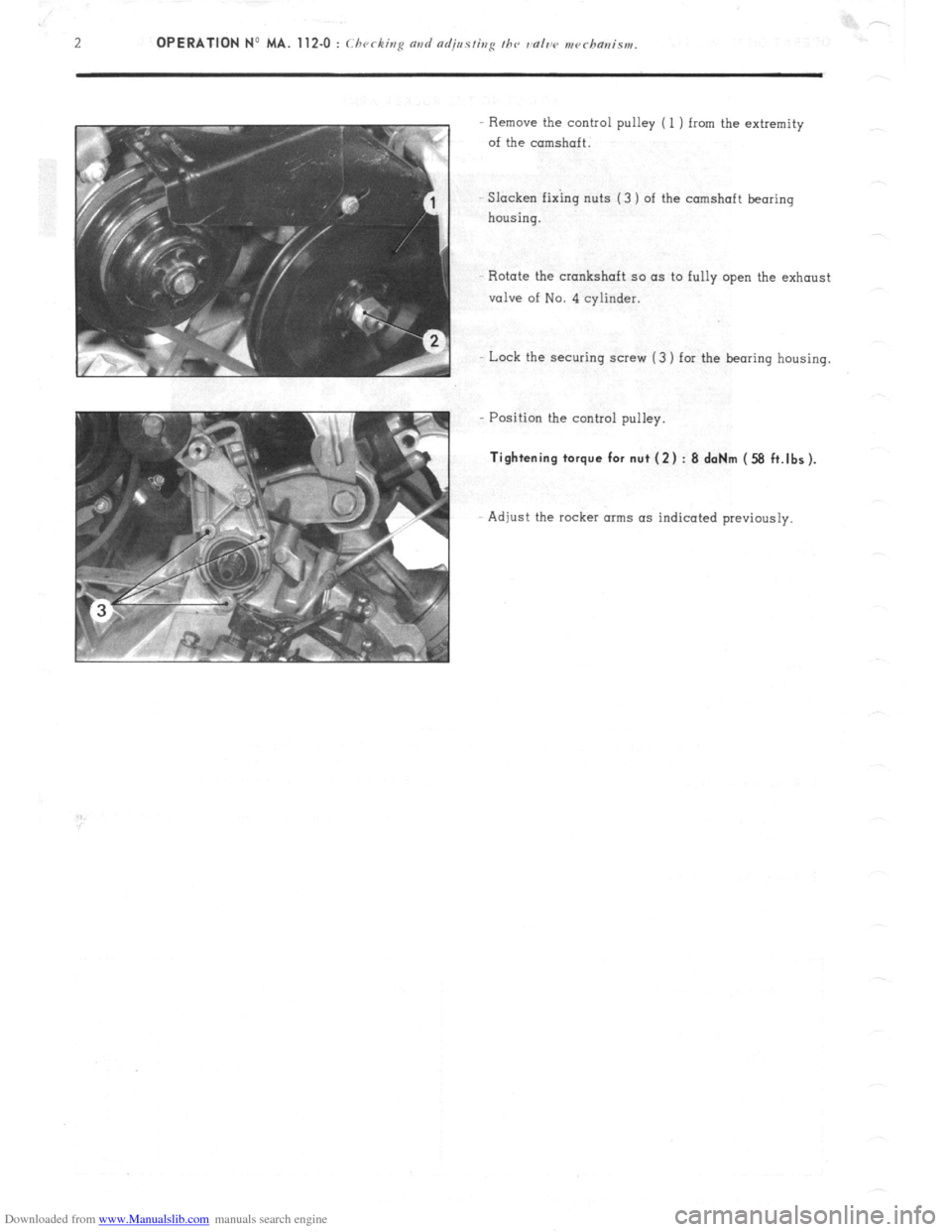
Downloaded from www.Manualslib.com manuals search engine Remove the control pulley ( 1 ) from the extremity
of the camshaft.
SIacken fixing nuts (3 ) of the camshaft bearing
housing.
Rotate the crankshaft so as to fully open the exhaust
valve of No. 4 cylinder.
Lock the securing screw (3 ) for the bearing housing.
Position the control pulley.
Tightening torque for nut (2) : 8 daNm (58 ft.lbs).
Adjust the rocker arms as indicated previously.
Page 112 of 394
Downloaded from www.Manualslib.com manuals search engine OPERATION No MA.IE. 144-00 : Chnract~~ristics o/ the H I,-jctrortic P dectrnr~ir
/i/c,1 iujcctim splcm. Op. MA.IE. 144-00 17
SUPPLEMENTARY AIR CONTROL ( 1 ) :
I’ / -...’ , _, ._,, ! .’ ! . .
At idling speed and when cold, the engine must produce more torque so as to counteract increased resistance
caused by friction. In addition to an enriched air fuel mixture, the engine also needs, when starting from cold
and during the warming-up period, to be supplied with supplementary air. The E.C.U. compensates for this
supplementary air by providing more fuel; the engine therefore has a larger amount of mixture at its disposal
to reach normal running temperature. The supplementary air control fitted in parallel with the throttle butterfly
supplies the supplementary air. The supplementary air control is heated only when the engine is running, and
its heater winding is supplied electrically as long as the ignition is switched on.
The location of the supplementary air control ‘on the engine block was selected for its good heat transfer charac-
teristics, and so as to subject the unit to the changing ambient temperature of the engine.
The opening section of the supplementary air control is automatically .adjusted according to the temperature, so
that the required idling speed is maintained regardless of engine temperature. When the latter increases, the air
channel is gradually reduced, until it is completely closed when the coolant temperature reaches approximately
+ 60” C. ->.:.. .-. : --.
,
The supplementary air control is situated at a representative spot fo.r engine running temperature. A bi-metal
spring actuates a rotary valve thereby altering the size of the air passage. Electric heating has the advantage
of allowing the. supplementary air to be adjusted at pre-set times. SWITCH ON THROTTLE BUTTERFLY SPINDLE :
,‘1 3 >_
The switch on the throttle butterfly spindle contains two contacts the idling speed contact, and the.full load contact.
The control contact, which.slides along a slot, closes the idling speed contact or the full load contact for a given
position of ‘the butterfly. The’ E.C.U. analyses the signals received so as to adjust the duration of injection.
Page 150 of 394
Downloaded from www.Manualslib.com manuals search engine OPERATION No MA. 173-O : Chrrkivp fhr prmd s,,pp/> Op. MA. 173.0 1
PETROL PUMP
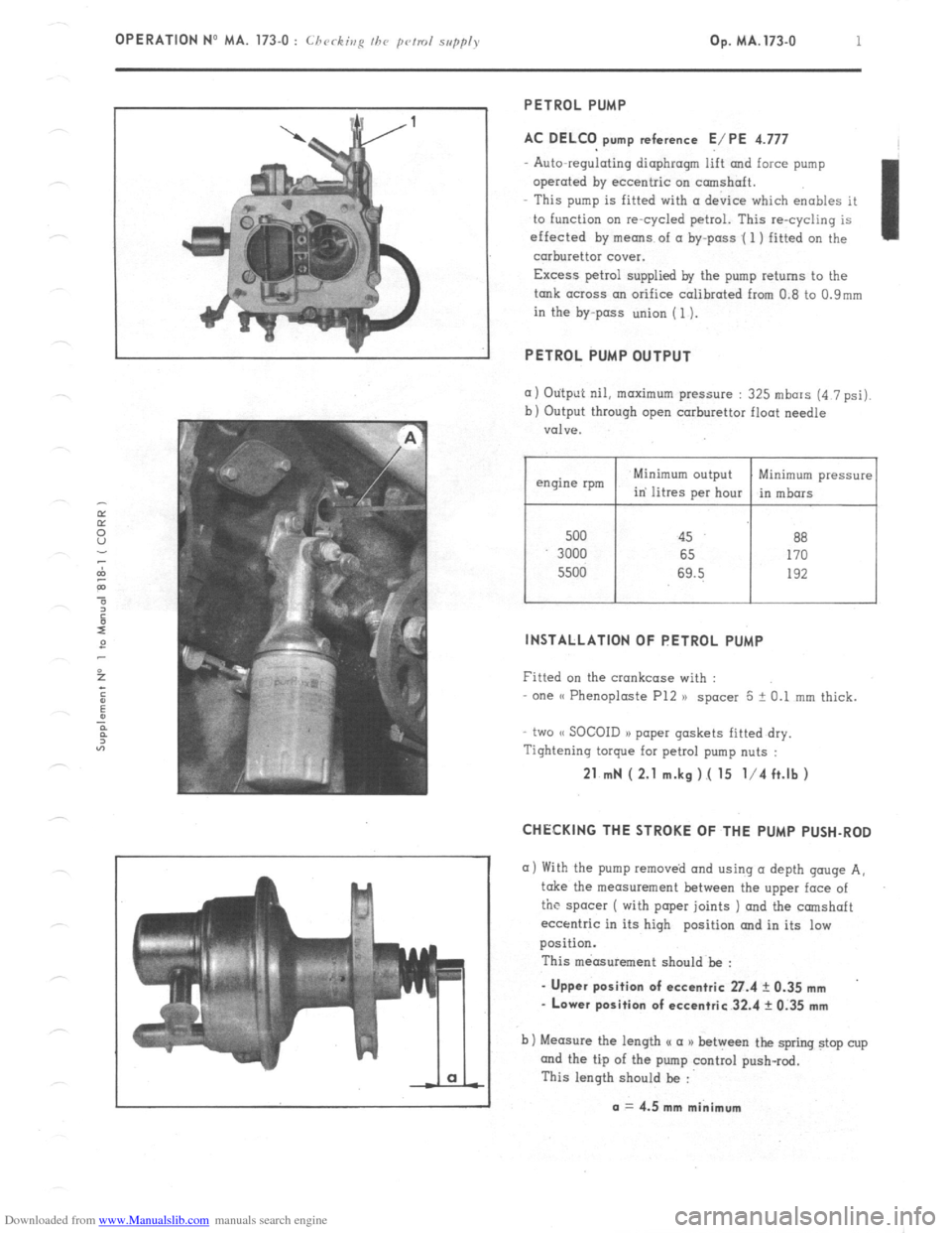
AC DELCO pump reference E/PE 4.777
Auto-regulating diaphragm lift and force pump
operated by eccentric on camshaft.
This pump is fitted with (I device which enables it
to function on re-cycled petrol. This re-cycling is
effected by means of a by-pass .( 1 ) fitted on the
carburettor cover.
Excess petrol supplied by the pump returns to the
tank across an orifice calibrated from 0.8 to 0.9mm
in the by-pass union (1).
PETROL PUMP OUTPUT
(I) Otitput nil, maximum pressure : 325 mbars (4 7 psi).
b) Output through open carburettor float needle
valve.
500 45 88
3000 65 170
5500 69.5 192
I I
Minimum pressure
in mbors
INSTALLATION OF PETROL PUMP
Fitted on the crankcase with :
one (( Phenoploste P12 )) spacer 5 + 0.1 mm thick.
two (< SOCOID a> paper gaskets fitted dry.
Tightening torque for petrol pump nuts :
21 mN ( 2.1 m.kg ).( 15 l/4 ft.lb )
CHECKING THE STROKE OF THE PUMP PUSH-ROD
a) With the pump removed and using (I depth gouge A,
take the measurement between the upper face of
the spacer ( with paper joints ) and the camshaft
eccentric in its high position and in its low
position.
This measurement should be :
- Upper position of eccentric 27.4 ? 0.35 mm
- Lower position of eccentric 32.4 rk 0.35 mm
b) Measure the length u a a) between the spring stop cup
and the tip of the pump control push-rod.
This length should be :
a = 4.5 mm minimum