heater Citroen CX 1983 1.G Owner's Guide
[x] Cancel search | Manufacturer: CITROEN, Model Year: 1983, Model line: CX, Model: Citroen CX 1983 1.GPages: 394
Page 363 of 394

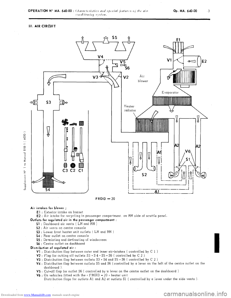
Downloaded from www.Manualslib.com manuals search engine III. AIR CIRCUIT
Heater
radiator
El
E2
Air
blower
I-
FROID - 20
__------- ----- _; Al
E2 : Air intake for recycling in passenger compartment, on RH side of scuttle panel.
Outlets for regulated air in the passenger compartment :
Sl
: Dashboard air vents ( LH and RH )
52 : Air vents on centre console
Air intakes for blower ;
El : Exterior intake on bonnet
53 : Lower front heater unit outlets ( LH and RH )
54 : Rear outlet on centre console
55 : De-misting and de-frosting of windscreen
56 : Centre outlet on dashboard
Distribution of regulated air :
Vl
: Distribution flap between outer and inner air-intakes ( controlled by C 1
V2 : Flap for cutting off outlets S3 -S 4 - S5 - S6 ( controlled by C 2 )
V3 : Distribution flap between outlets S3 - S4 and S5 - S6 ( controlled by C 2
V4 : Distribution flap between outlets S5 and S6 (controlled by a lever on the left of the centre outlet on the
dashboard ).
V5 : Cut-off flap for outlet S6 ( controlled by ‘a lever on the centre outlet on the dashboard )
V6 : On vehicles fitted with the u FROID - 20 )I heater unit
Distribution flaps for outlets Al and A2 at outlets Sl ( controlled by a lever under the side vents ),
Page 367 of 394

Downloaded from www.Manualslib.com manuals search engine OPERATION No MA. 640-00 : (hnrnct~~tis~ics md special jenttrrvs of the nir-
coi~ditiouing systcw. 1 Op. MA. 640-00
7
VII. WIRING DIAGRAMS FOR COOLING FAN AND AIR-CONDITIONING SYSTEM CONTROLS
7.; 1976 - Special features :
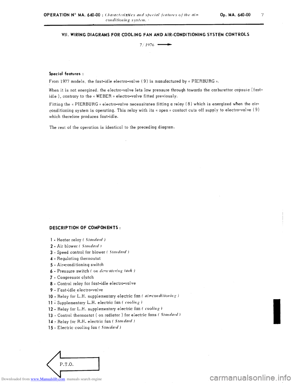
From 1977 models, the fast-idle electro-valve ( 9) is manufactured by (( PIERBLJRG )).
When it is not energized. the electro-valve lets low pressure through to.wards the carburettor capsule (fast-
idle ) I contrary to the (( WEBER )) electro-valve fitted previously.
Fitting the (( PIERBURG )) electro-valve necessitates fitting a relay (8) which is energized when the air-
conditioning system is operating. This relay with its N open )) contact cuts off supply to electro-valve ( 9)
which therefore produces fast-idle.
The rest of the operation is identical to the preceding diagram. DESCRIPTION OF COMPONENTS :
1
- Heater relay ( standard )
2 - Air blower ( Stmdnrd )
3 - Speed control for blower f Stnudnrd )
4 - Regulating thermostat
5 - Air-conditioning switch
6 - Pressure switch ( on dc-wnkrivg t~rrk ,)
7 - Compressor cl.utch
8 - Control relay for fast-idle electro-valve
9 - Fast-idle electro-valve
10 - Relay f0r’L.H. supplementary electric fan ( air-rorzditio)litlg J 11
i Supplementary L.H. electric fan ( cooliug )
12 - Relay for L.H. supplementary electric fan ( cooling ) 13
- Control thermostat ( on radiator ) for electric fans ( Standard ) 14
- Relay for R.H. electric fan ( Stmzdurd 1
15 - Electric cooling fan ( Stnrrdurd )
e
P.T.O.
Page 380 of 394

Downloaded from www.Manualslib.com manuals search engine Op MA. 642-00 5 II. DEVICE FOR INCREASING THE HEATING OF THE PASSENGER COMPARTMENT
This device entails modifying the following components
- Heater distribution box ( outlets towards side vents unplugged, different radiator )
Side vents with twin outlets ( ambient or heated air )
Addition of Westaflex ducts ( link from heater distribution box to side vents ). III. WATER TEMPERATURE GAUGE
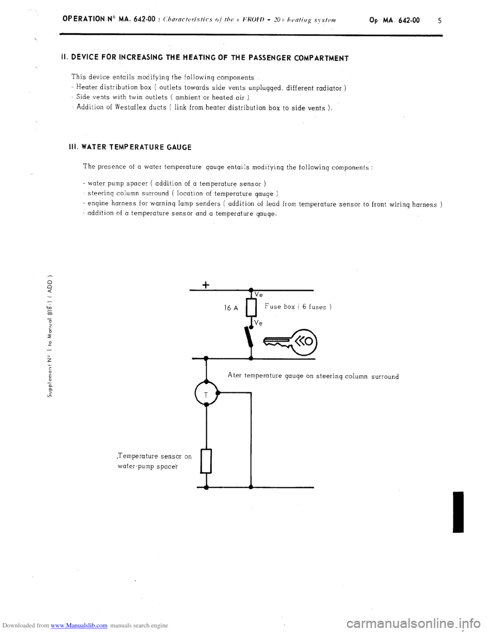
The presence of a water temperature gauge entails modifying the following components :
- water pump spacer ( addition of a temperature sensor )
steerinq column surround ( location of temperature gauqe )
- engine harness for warning lamp senders ( addition of lead from temperature sensor to front wiring harness )
addition of a temperature sensor and a temperature gauge.
Ater temperature gauge on steering column surround
.Temperature sensor on
water-pump spacer
P