heater Citroen CX 1983 1.G User Guide
[x] Cancel search | Manufacturer: CITROEN, Model Year: 1983, Model line: CX, Model: Citroen CX 1983 1.GPages: 394
Page 172 of 394
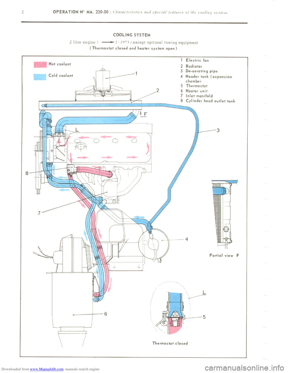
Downloaded from www.Manualslib.com manuals search engine COOLING SYSTEM
L litre enlyne f
-I l’r’i ) except optional towing equipment (Thermostat closed and heater system open)
Hot cool.n+
>Id coolant I Electric fan
2 Radiator
3 De-aerating pipe
4 Header tank (expansion
chamber
5 Thermostat
2 6 Heater unit
7 Inlet manifold
8 Cvlinder head outlet tank
Partial view F
II Thermostot closed
Page 173 of 394
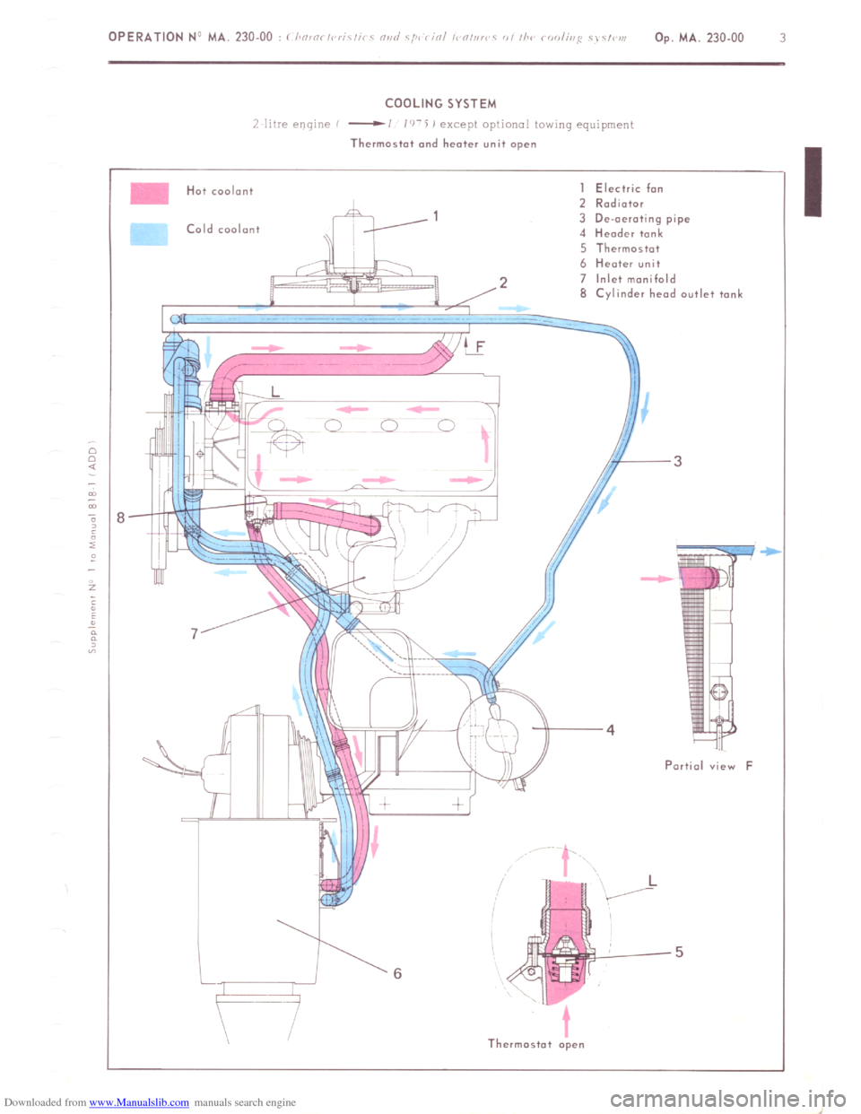
Downloaded from www.Manualslib.com manuals search engine COOLING SYSTEM
/ 11’re e!!qlric
-1 1’1-5 j except oprlonal row,ng equ,pmenr
Thermostat and heater unit open
Hot coolant
Cold coolant I Electric fan
2 Rodiotor
3 De-aerating pipe
4 Header tank
5 Thermostot
6 Heater unit
2 7 Inlet manifold
8 Cylinder heod outlet tonL
-3
Portia1 view F
Thermostat open
Page 174 of 394
Downloaded from www.Manualslib.com manuals search engine -
-
‘F
L
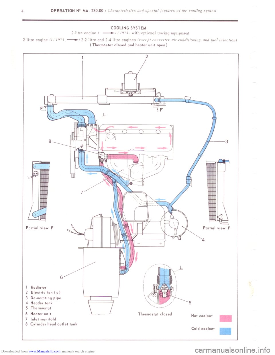
Radiator
! Electric fan ( 5)
I De-oeroting pipe
I Header tank
i Thermostot
I Heater unit
Inlet manifold
i Cylinder head outlet tank Thermostat closed
Hot coolant
Cold coolont -
Page 175 of 394
Downloaded from www.Manualslib.com manuals search engine OPERATION No MA. 230.00 : ( i ‘
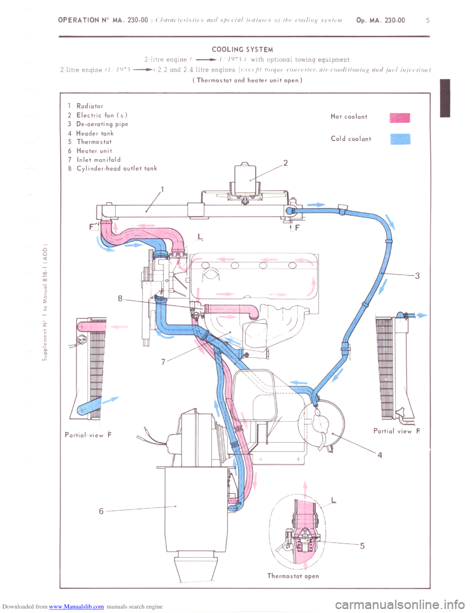
Electric fan ( s )
3 De-oerot~ng pipe 4
Header tank
5 Thermostat 6
Heater unit
7 Inlet manifold
8 Cylinder-heod outlet tank
8 -‘I KY - -
Partial-view F - Partial view F
6
Thermostat open
Page 176 of 394
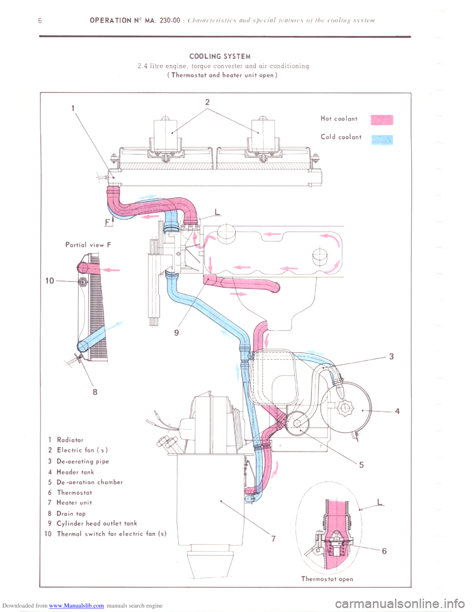
Downloaded from www.Manualslib.com manuals search engine COOLING SYSTEM
2 4 litre engine, torque converter and air conditinninq (Thermostat and heater unit open)
Partial view F
8
1 Radiator
2 Electric fon (5)
3 De-aerating pipe
4 Header tank
5 De-aeration chamber
6 Thermostat
7 Heater unit
8 Drain top
9 Cylinder head outlet tank Cold coolant
,
I-
J1
- 0 Thermal switch for electric fan (s)
l-J 7
6
Thermostat open
Page 177 of 394
Downloaded from www.Manualslib.com manuals search engine OPERATION NJ MA. 230.00 : 1 i !O,Oi ,V,iC,i< c “ii<, ‘/QC < iOi ,< “,,i!< 0, ii’<
Op. MA. 230.00 7
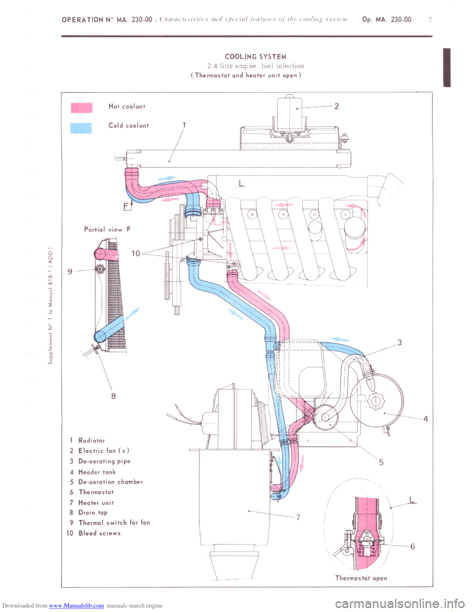
COOLING SYSTEM
2 4 litre engine fuel injection (Thermostat and heater unit open)
Hat coolant
Cold coolant
Partial view F
1 Rodiotor
2 Electric fon (5)
3 De-aerating pipe
4 Header tank
5 De-aeration chamber
6 Thermostat
7 Heater unit
6 Drain top
9 Thermal switch for fan
0 Bleed screws
Thermast.t open
Page 178 of 394
Downloaded from www.Manualslib.com manuals search engine OPERATION No MA. 230.0 : M k
08 ,ri,y r,i, //I<’ roo/i,ip c, s,w,,.
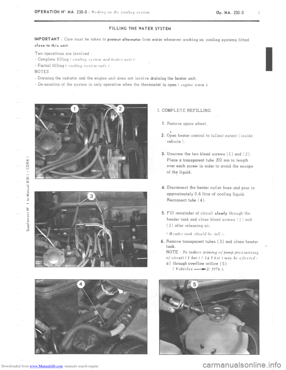
Op. MA. 230.0 1 FILLING THE WATER SYSTEM
IMPORTANT
: Core must be token to protect alternator from water whenever working on cooling systems fitted close to this unit.
Two operations are involved
- Complete filling i roolir~g c~s~<,v, nvd bvolvr ,,ail ,
- Partial filling I roolir,p ~J~S/IW, oul~* 1
NOTES
Draining the radiator and the engine unit does not involve draining the heater unit.
- De-aeration of the system is only operative when the thermostat is open 1 v,rgiur wnnu J.
I. COMPLETE REFILLING 1. Remove
spare wheel
.
2. Open heater control to fullest extent ( inside
vehicle 1.
3. Unscrew the two bleed screws ( 1 ) and ( 2 ).
Place a tronsporent tube
200 mm in length
over each screw in order to ovoid the escape
of the liquid.
4. Disconnect the heater outlet hose and pour in
approximately 0.6 litre of cooling liquid.
Reconnect tube ( 4).
5. Fill remainder of circuit slowly through the
header tank and close bleed screws I 1) and
( 2) after releasing air
6. Remove transparent tubes ( 3) and close header
tank.
NOTE : To induce primitzg o/pum~,~~~sseri;irrp
o/ circuit I I bar 1 f 14. 5 psi ) may b+ r~i/vrtd:
(11 through overflow orifice ( 5)
I Vehicles -2/ 1976 ).
Page 179 of 394
Downloaded from www.Manualslib.com manuals search engine 2 OPERATION No MA. 230-O : II .h’ 0, fug Ol, I/7‘, rodir,p sys/w1.
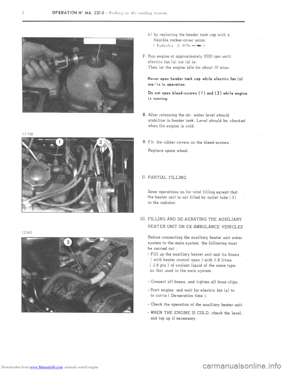
b) by replacing the header tank cap with a
flexible rocker-cover union
I V~~/7id<~S 2/ IU7h - ,
7. Run engine at approximately 2000 rpm until
electric fan (5) cut (5) in.
Then let the engine idle for about 10 mins.
Never open header tank cap while electric fan (5)
ore/is in operation.
Do not open bleed-screws ( 1 ) and (2) while engine
is running.
8. After releasing the air. water level should
stabilize in header tank. Level should be checked
when the engine is cold.
9. Fit the rubber covers cm the bleed-screws.
Replace spare wheel.
II. PARTIAL FILLING
Same operations as for total filling except that
the heater unit is not filled by outlet tube ( 3)
to the radiator.
111. FILLING AND DE-AERATING THE AUXILIARY
HEATER UNIT ON CX AMBULANCE VEHICLES
Before connecting the auxiliary heater unit water
system to the main system. the following must
be carried out :
- Fill up the auxiliary heater unit and its hoses
( with heater control open I with 1.6 litres
( 2.8 pts 1 of coolant liquid of the some type
as that used in the main
system.
- Connect all hoses. and tiqhten 011 hose clips.
-Stat engine. and wait for electric fan (5) to
to cut-in ( De-aeration time 1.’
- Check the operation of the auxilioly heater unit.
- WHEN THE ENGINE IS COLD, check the level,
and top up if necessary.
Page 289 of 394
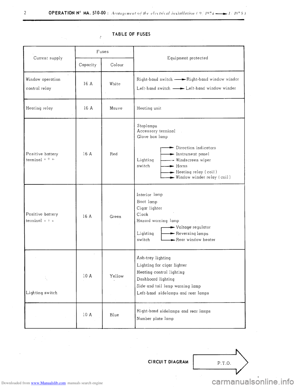
Downloaded from www.Manualslib.com manuals search engine TABLE OF FUSES
Current supply
findow operation
ontrol relay Fuses
Equipment protected
Capacity Colour
Right-hand switch -Right-hand window winder
16 A White
Left-hand switch - Left-hand window winder
Ieating relay 16 A Mauve Heating unit
Stoplamps
Accessory terminal
Glove box lamp
‘ositive battery
erminal (( + )). 16
A Red Direction indicators
E Instrument panel
Lighting -- Windscreen wiper
switch Horns
Heating relay ( coil )
Window winder relay ( coil )
‘ositive battery
erminal (( t 1) 16 A Green Interior lamp
Boot lamp
Cigar lighter
Clock
Hazard warning lamp
Lighting
switch
E
Voltage’ regulator
Reversing lamps
Rear window heater
Ash-tray lighting
10 A Yellow Lighting for cigar lighter
Heating control lighting
Dashboard lighting
,ighting switch Side- and tail lamp warning lamp
Left-hand sidelamps and rear lamps
10 A Blue Right-hand sidelamps and rear lamps
Number plate lamp Cl RCUI T DIAGRAM
r>
Page 297 of 394
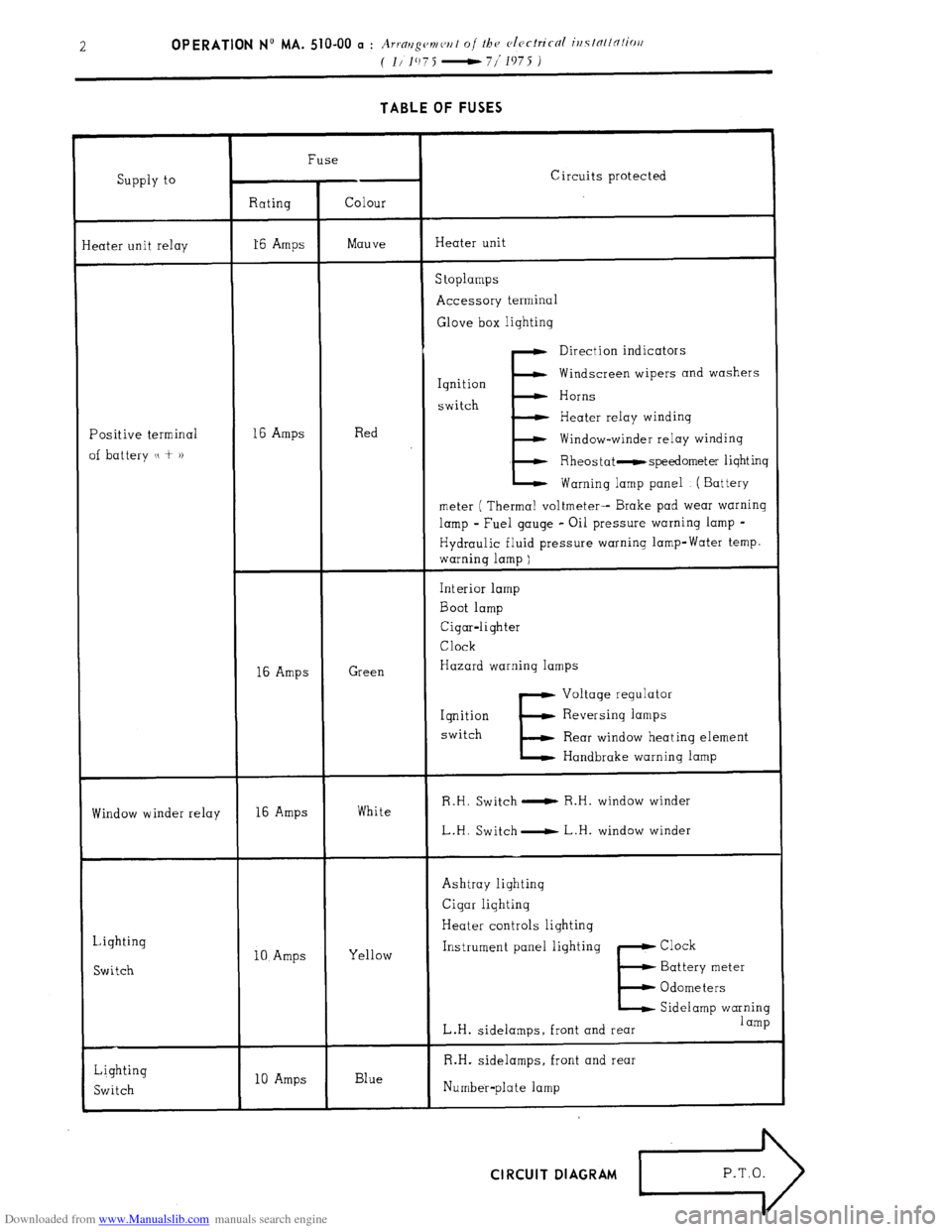
Downloaded from www.Manualslib.com manuals search engine TABLE OF FUSES
Supply to
eater unit relay Fuse
Circuits protected
Rating Colour
16 Amps Mauve Heater unit
S toplamps
Accessory terminal
Glove box lightinq
Positive terminal
of battery u + )) 16 Amps Red
E Direction indicators
Ignition Windscreen wipers and washers
switch Horns
Heater relay windinq
Window-winder relay winding
Rheostat -speedometer lighting
Warning lamp panel ( Battery
meter ( Thermal voltmeter-- Brake pad wear warning
lamp - Fuel gauge - Oil pressure warning lamp -
Hydraulic fluid pressure warning lamp-Water temp.
warning lamp )
16 Amps Green Interior lamp
Boot lamp
Cigar-lighter
Clock
Hazard warning lamps
E Voltage regulator
Iqnition Reversing lamps
switch
Rear window heating element
Handbrake warning lamp
Window winder relay 16 Amps White R.H. Switch 0 R.H. window winder
L.H. Switch- L.H. window winder
Lighting
Switch 10 Amps Yellow Ashtray lighting
Cigar lighting
Heater controls lighting
Instrument panel lighting Clock
E Battery meter
Odometers
Sidelamp warning
L.H. sidelamps, front and rear 1 amp
Lighting
Switch 10 Amps Blue R.H. sidelamps, front and rear
Number-plate lamp CIRCUIT DIAGRAM
>
P.T.O.