Temperature Citroen CX 1984 1.G Owner's Manual
[x] Cancel search | Manufacturer: CITROEN, Model Year: 1984, Model line: CX, Model: Citroen CX 1984 1.GPages: 394
Page 139 of 394
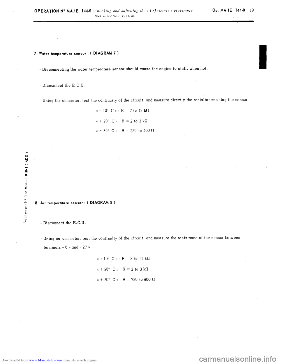
Downloaded from www.Manualslib.com manuals search engine 7. Water temperature sensor : ( DIAGRAM 7 )
- Disconnecting ‘the water temperature sensor should cause the engine to stall. when hot.
- Disconnect the E.C U
Using the ohmmeter, test the continuity of the circuit. and measure directly the resisitance using the sensor
cc - 10’ C )) R = 7 to 12 kR
cc + 20” C )t R = 2 to 3 kQ
cc t 80” C H R -. 250 to 400 Q
e
2
ii 8. Air temperature sensor : ( DIAGRAM 8 )
E
-E
?
U-J
- Disconnect the E.C.U. -
Using an ohmmeter, test the continuity of the circuit. and measure the resistance of the sensor between
terminals (( 6 )) and (( 27 ))
(c-10’ CH. R-8toIlkQ
N t 20” C 1) R = 2 to 3 kQ
tt + 50” C n R x 750 to 900 !J
Page 140 of 394
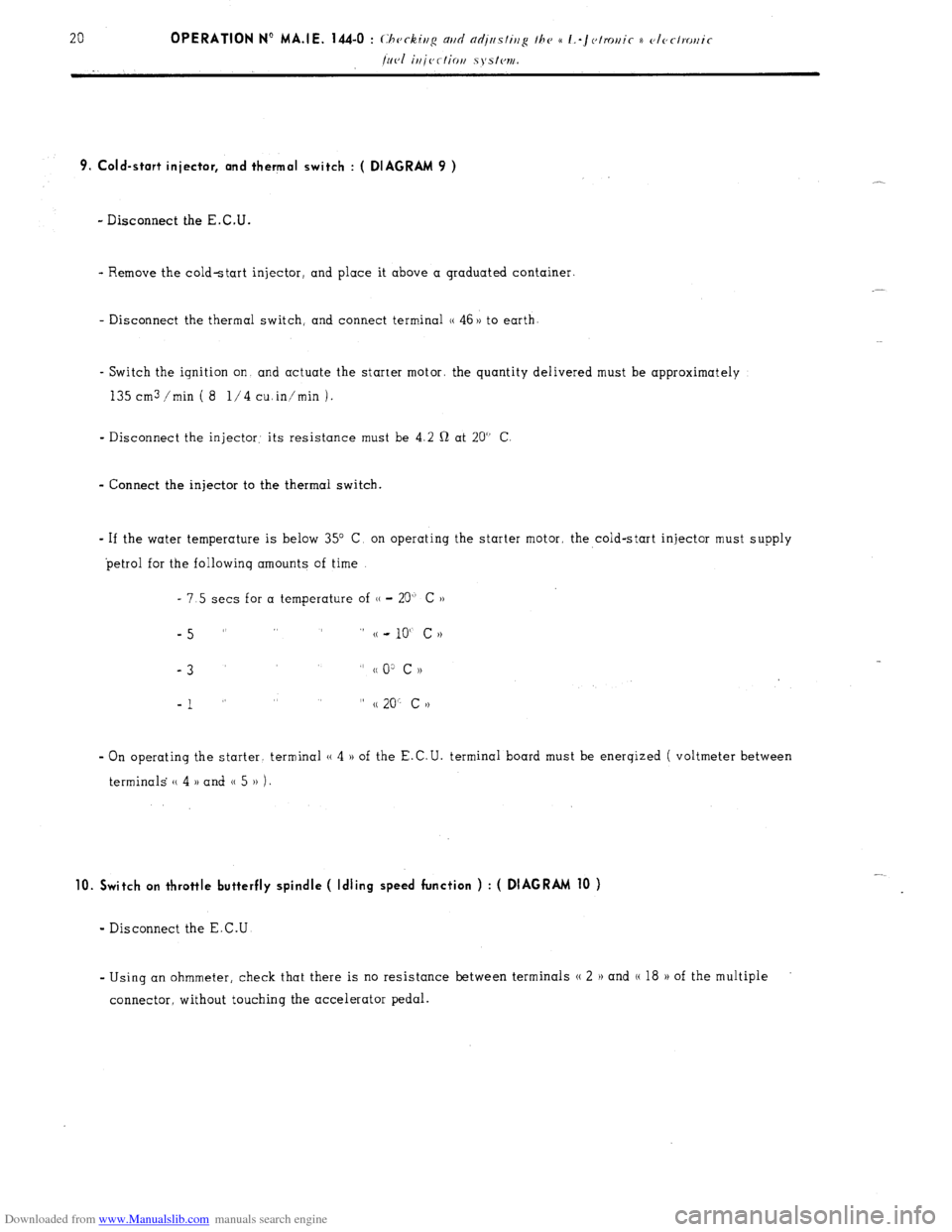
Downloaded from www.Manualslib.com manuals search engine 9. Cold-start injector, and thermal switch : ( DIAGRAM 9 )
- Disconnect the E.C.U.
- Remove the cold-start injector, and place it above a graduated container.
- Disconnect the thermal switch, and connect terminal (( 46 )) to earth
- Switch the ignition on and actuate the starter motor. the quantity delivered must be approximately
135 cm3 /min ( 8 l/4 cuin’min 1.
- Disconnect the injector: its resistance must be 4.2 Q at 20” C
- Connect the injector to the thermal switch.
- If the water temperature is below 35” C, on operating the starter motor, the cold-start injector must supply
petrol for the followinq amounts of time
- 7.5 sets for a temperature of (( - 20” C ))
-5 ” ” (( - 10“ c N
-3
” cc 0: c ))
-1 ” ” (( 20” c >)
- On operating the starter. terminal (( 4 )) of the E.C.U. terminal board must be enerqized ( voltmeter between
terminals (( 4 )) and 0 5 )) 1.
10. Switch on throttle butterfly spindle ( Idling speed function ) : ( DIAGRAM 10 )
- Disconnect the E.C.U
- Using an ohmmeter, check that there is no resistance between terminals N 2 H and (( 18 H of the multiple
connector, without touching the accelerator pedal.
Page 149 of 394
Downloaded from www.Manualslib.com manuals search engine 28 OPERATION N” MA.IE. 144-O : Ch <,c ,ng n,,d nlfjusfiup Ihe u I.-~<~tro,,ir i) <~lrr/mr,ir k’
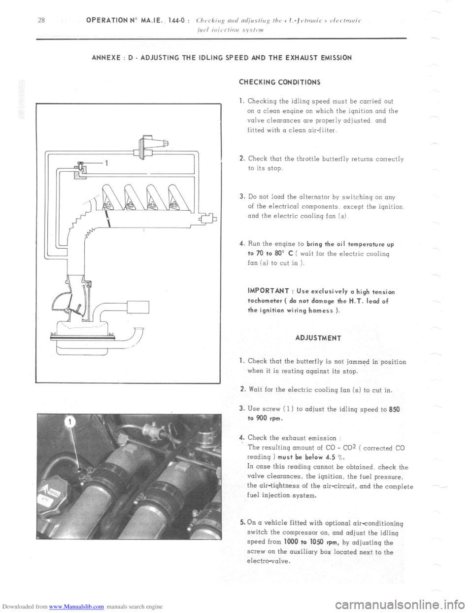
/,,,.I i,,jrr/io,, S~S,W1, ANNEXE : D - ADJUSTING THE IDLING SPEED AND THE EXHAUST EMISSION
CHECKING CONDITIONS
1.
Checking the idling speed must be carried out
on a clean engine on which the ignition and the
valve clearances are properly adjusted and
fitted with a clean air-filter.
2. Check that the throttle butterfly returns correctly
to its stop.
3. Do not load the alternator by switching an any
of the electrical components, except the iqnition
and the electric cooling fan (s) 4.
Run the engine to bring the oil temperature up
to 70 +o 80’ C ( wait for the electric cooling
fan is) to cut in ). IMPORTANT : Use exclusively (I high tension
tachometer ( do not damage the H.T. lead of
the ignition wiring harness ).
ADJUSTMENT
1. Check that the butterfly is not jammed in position
when it is resting against its stop.
2. Wait for the electric cooling fan (s) to cut in.
3. Use screw ( 1 ) to adjust the idling speed to 850
to 900 rpm.
4. Check the exhaust emission :
The resulting amount of CO - CO2 ( corrected CO
reading 1 must be beI& 4.5 %.
In case this reading cannot be obtained, check the
valve clearances, the ignition, the fuel pressure,
the air-tightness of the aircircuit, and the complete
fuel injection system.
5. On (I vehicle fitted with optional oirtonditioning
switch the compressor on, and adjust the idling
speed from 1000 to 1050
rpm, by adjusting the
screw on the auxiliary box located next to the
electro-vol”e.
Page 165 of 394
Downloaded from www.Manualslib.com manuals search engine OPERATION No MA. 220-O : (.hrrkinfi Ih e oil pr~ssrrrc m the rehicle Op. MA. 220.0 1
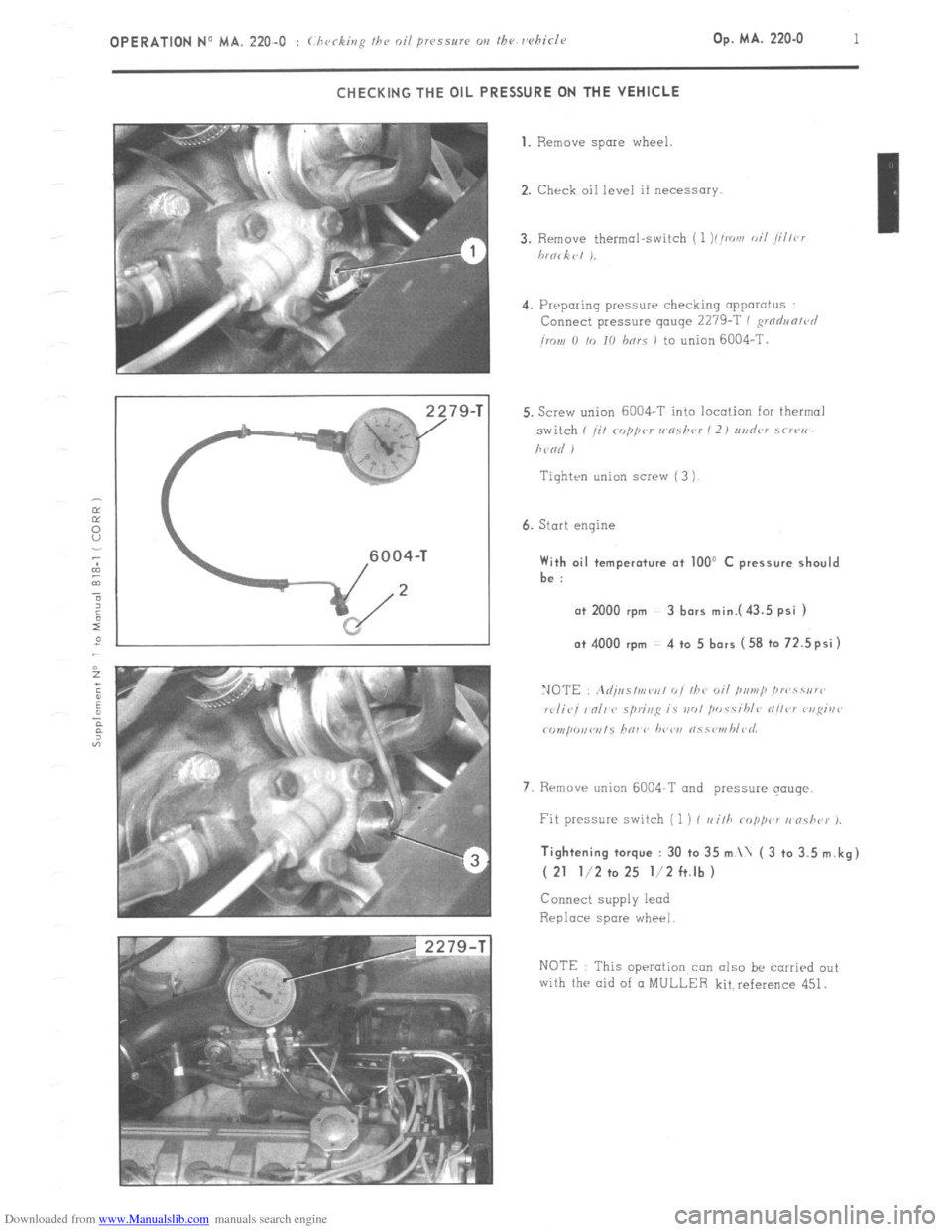
CHECKING THE OIL PRESSURE ON THE VEHICLE
79-T 1. Remove spare
wheel.
2. Check oil level if necessary.
4. Preparing pressure checking apparatus
Connect pressure gauge 2279-T ( ,wdun/r~l
imn 0 /o IO hnrs 1 to union 6004-T.
Tiqhten union screw ( 3 )
6. Start engine With oil temperature at 100’ C pressure should
be :
a+ 2000 rpm 3 bars mini43.5 psi ) o+ 4000 rpm 4 to 5 bars (58 to 72.5psi)
7. Rrmave union 6004-T and pressure qouqe. Tightening torque : 30 to 35 m \ ( 3 to 3.5 m.kg)
( 21 l/2 to 25 l/2 ft.lb )
Connect supply lead
Replace spare wheel
NOTE This operation con also be carried out
with the aid of CI MULLER kit,reference 451.
Page 170 of 394
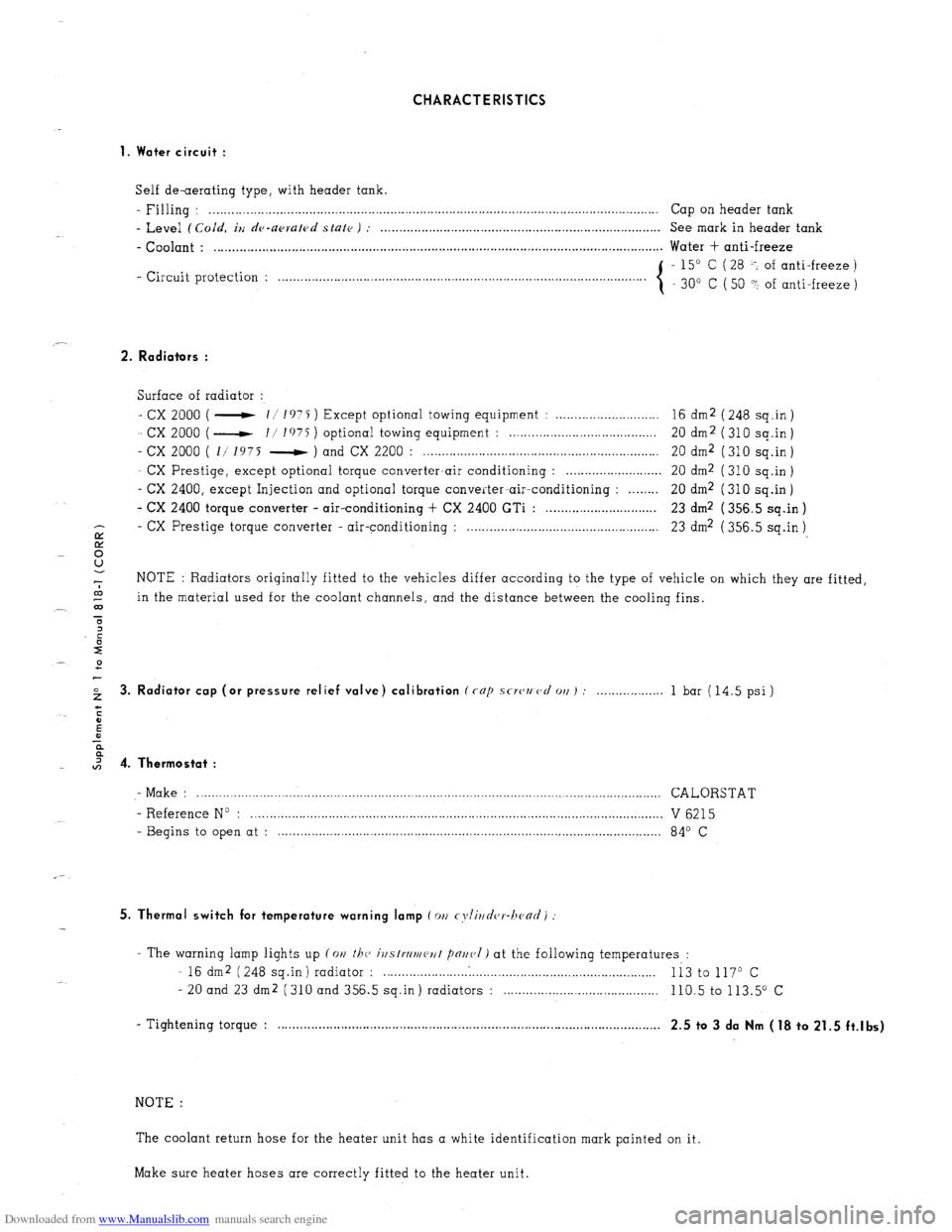
Downloaded from www.Manualslib.com manuals search engine CHARACTERISTICS
1. Water circuit :
Self de-aerating type, with header tank.
- Filling : . . . . . . . .._................................................................................................................ Cap on header tank
- Level (Cold, iu de-upruled state ) : . . . . . . . . . . . . . . . . . . . . . . . . . . . . . . . . . . . . . . . . . . . . . . . . . . . . . . . . . . . . . . . . . . . . . . . . . . . . See mark in header tank
- Coolant : . . . . . . . . . . . . . . . . . . . . . . . . . . . . . . . . . . . . . . . . . . . . . . . . . . . . . . . . . . . . . . . . . . . . . . . . . . . . . . . . . . . . . . . . . . . . . . . . . . . . . . . . . . . . . . . . . . . . . . . . .. Water + anti-freeze
- Circuit protection : - 15” C ( 28 -: of anti-freeze )
. . . . . . . . . . . . . . . . . . . . .
30” C ( 50 ? of anti-freeze )
2. Radiators :
Surface of radiator :
- cx 2000 ( - 11 1975 ) Except optional towing equipment : . . . . . . . . . . . . . . . . . . . . . . . . . . . . 16 dm2 ( 248 sq.in )
- cx 2000 ( - I/ I’)75 ) optional towing equipment : . . . . . . . . . . . . . . . . . . . . . . . . . . . . . . . . . . . . . . 20 dm2 (310 sq.in)
- cx 2000 ( 1/ 1975 - ) and CX 2200 : . . . . . . . . . . . . . . . . . . . . . . . . . . . . . . . . . . . . . . . . . . . . . . . . . . . . . . . . . . . . . . . . 20 dm2 ( 310 sq.in )
- CX Prestige, except optional torque converter-air conditioning : . . . . . . . . . . . . . . . . . . . . . . . . . . 20 dm2 ( 310 sq.in )
- CX 2400, except Injection and optional torque converter-air-conditioning : . . . . . . . . 20 dm2 (310 sq.in)
- CX 2400 torque converter - air-conditioning + CX 2400 GTi : . . . . . . . . . . . . . . . . . . . . . . . . . . . . . . 23 dm2 ( 356.5 sq.in )
- CX
E Prestige torque converter - air-conditioning : . . . . . . . . . . . . . . . . . . . . . . . . . . . . . . . . . . . . . . . . . . . . . . . . . . . . 23 dm2 ( 356.5 sq.in )
8
-7 NOTE : Radiators originally fitted to the vehicles differ according to the type of vehicle on which they are fitted,
co
_- 03 in the material used for the coolant channels, and the distance between the cooling fins.
T
2 3. Radiator cap (or pressure relief valve) calibration (rap scwzmcl 011) : . . . 1 bar (14.5 psi)
I 4. Thermostat :
- Make : .............................................................................................................................. CALORSTAT
- Reference No : ................................................................................................................ V 6215
- Begins to open at : ........................................................................................................ 84’ C
5. Thermal switch for temperature warning lamp (011 cyli~~d(,r-hc~ad)
- The warning lamp lights up (on the, ivstrrlmeut pnr~(,I) at the following temperatures :
- 16 dm2 (248 sq.in) radiator : . . . . . . . . . . . . .
Ii3 to 117O c
- 20 and 23 dm2 (310 and 356.5 sq.in) radiators : . . . . 110.5 to 113.5” c
- Tightening torque : . . . . . . . . . . . . . . . . . . . . . . . . . . . . . . . . . . . . . . . . . . . . . . . . . . . . . . . . . . . . . . . . . . . . . . . . . . . . . . . . . . . , . . . . . . . . . . . . . . . . . . . .
2.5 to 3 da Nm (18 to 21.5 ft.lbs)
NOTE :
The coolant return hose for the heater unit has a white identification mark painted on it.
Make sure heater hoses are correctly fitted to the heater unit.
Page 186 of 394
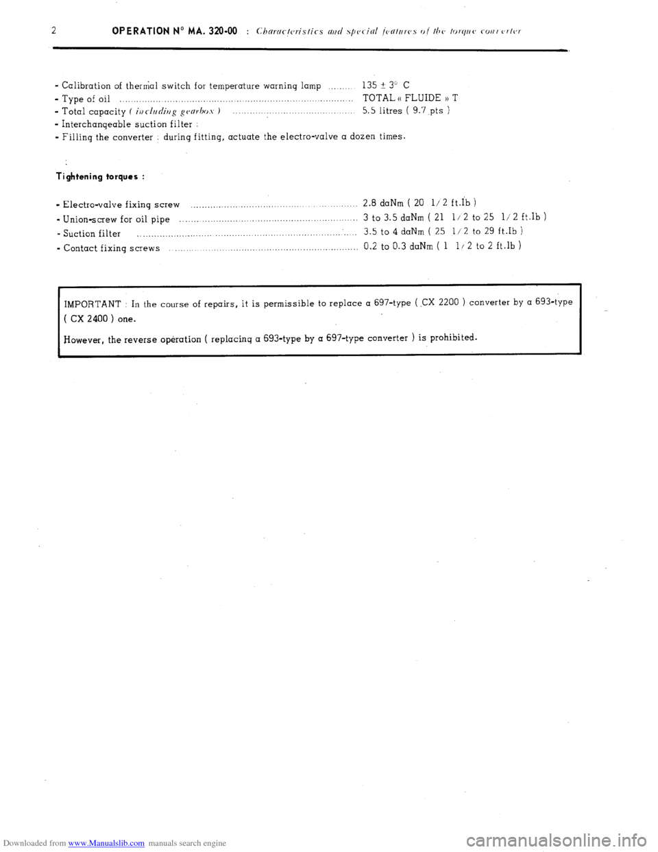
Downloaded from www.Manualslib.com manuals search engine - Calibration of thermal switch for temperature warning lamp .__._... 135 ? 3” C
- Type of oil . . .._..__.._._..___._._._._._.................,,.........._..._..._................. TOTAL (( FLUIDE 1) T
- Total capacity f
iur//rdiir/g ~~arhos ) .._._.._.......................... 5.5 litres ( 9.7,pts )
- Interchanqeable suction filter
- Filling the converter during fitting. actuate the electro-valve a dozen times.
Tightening torques :
- Electra-valve fixing screw ............................................................ 2.8 daNm ( 20 l/2 ft.Ib )
- Union-screw for oil pipe ............................................................... 3 to 3.5 daNm ( 21 l/ 2 to 25 l/ 2 ft.Ib )
- Suction filter .................................................... ........... ............. 3.5 to 4 daNm ( 25 l/2 to 29 ft.Ib )
- Contact fixing screws ................................................................... 0.2 to 0.3 daNm ( 1 11 2 to 2 ft.lb )
IMPORTANT : In the course of repairs, it is permissible to replace a 697-type ( .CX 2200 ) converter by a 693-type
( CX 2400 ) one.
However, the reverse operation ( replacing a 693-type by a 697-type converter ) is prohibited.
Page 292 of 394
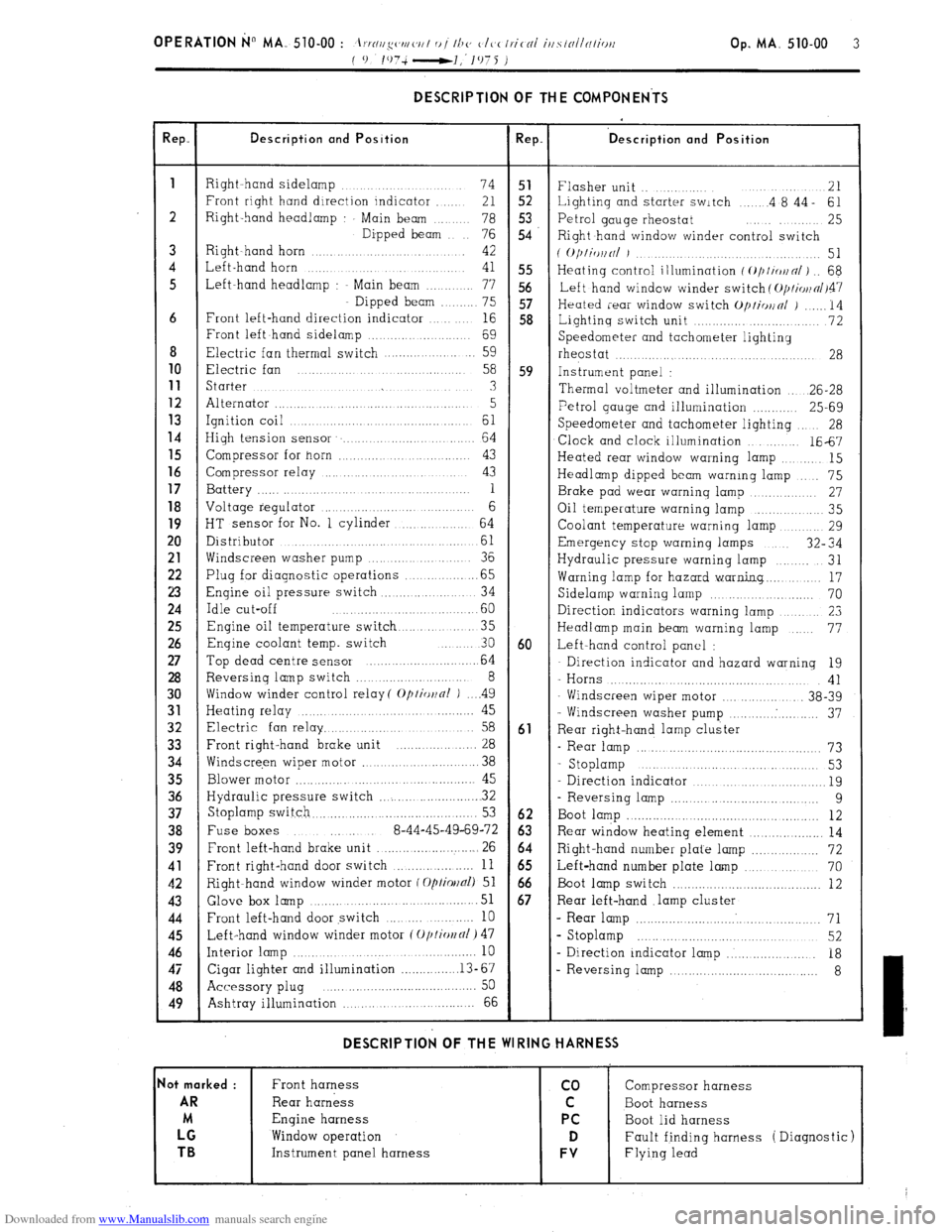
Downloaded from www.Manualslib.com manuals search engine OPERATION No MA. 510-00 : \m//l‘!yc~tl/ <‘,/I 0 t Ih<’ <‘It,< Ir.itnl iusrtlllnliritt Op. MA. 510-00 3
f 0 lO7i-l,‘1975 )
DESCRIPTION OF THE COMPONENTS
!ep. Description and Position Rep. ‘D escription and Position
1
Right hand sidelamp ...... 74 51
Flasher unit .. ....... 21
Front right hand direction indicator ..... 21 52 Lighting and starter switch .... .4 8’44- 61
2 Right-hand headlamp Main beam .. 78 5.3
76 54 Petrol gauge rheostat ........ 25
Dipped beam
Right hand window winder control switch
3 Right~hand horn ............ 42
( O/)liWlNl J ................. 51
4 Left-hand horn ...
41 55 Heating control illumination f ~///io~n/) .. 68
5 Left-hand headlamp : Main beam ....... 77 56
Left hand window winder switch ( O/JI~OII~/~~~
Dipped beam ...... 75 57
Heated rear window switch Op/io~nl j ...... 14
6 Front left-hand direction indicator ... 16 58
Lightinq switch unit ............. ........... 72
Front left hand sidelamp ................. 69
Speedometer and tachometer lighting
8 Electric fan thermal switch .................. 59
rheostat ....... ...... .................... 28 10
Electric fan .......
58 59 Instrument panel : 11
Starter ...... ... .............. .......... 3
Thermal voltmeter and illumination .. 26-28 12
Alternator ............................ ........ 5 13 Petrol gauge and illumination ............ 25-69
Ignition coil ... ......... .............. 61 14
Speedometer and tachometer lighting 28
High tension sensor ....................... 64
Clock and clock illumination ....... 1667 15
Compressor for horn ............ ..... ...... 43
Heated rear window warning lamp ....... 15 16
Compressor relay ................... ..... 43
Headlamp dipped beam warning lamp ... 75 17
Battery ............. .... .. 1
Brake pad wear warning lamp .......... 27 18
Voltage regulator ......................... 6
Oil temperature warning lamp ............ 35
19
HT sensor for No. 1 cylinder ........... 64
Coolant temperature warning lamp ....... 29 20
Distributor ..................... ...........
61 Emergency stop warning lamps 32” 34
21
Windscreen washer pump ............. 36
Hydraulic pressure warning lamp ...... 31 22
Plug for diagnostic operations ............. .65
Warning lamp for hazard warning.. ...... 17 23
Engine oil pressure switch .............. .. 34
Sidelamp warning lamp ................... 70 24
Idle cut-off ....................... .60
Direction indicators warning lamp ........... 23 25
Engine oil temperature switch ........... 35
Headlamp main beam warning lamp ... 77 26
Enqine coolant temp. switch ... 30 60 Left-hand control panel : 27
Top dead centre sensor ........................ 64 Direction indicator and hazard warning 19 28
Reversing lamp switch ........................ 8
- Horns .................................... 41 30
Window winder control relay( Optior~nl ) .. ..4 9
Windscreen wiper motor ............... 38-39 31
Heating relay ............ ..................... 45
- Windscreen washer pump .......... . .......... 37 32
Electric fan relay ................................ 58 61
Rear right-hand lamp cluster 33
Front right-hand brake unit ................. 28
- Rear lamp ............................................... 73 34
Windscre,en wiper motor ........................ 38
- Stoplamp ............. .....
............ 53
35
Blower motor ............ .............................. 45
Direction indicator ................................... 19 36
Hydraulic pressure switch ...................... . 32
- Reversing lamp ..................................... 9 37
Stoplamp switch.. ......................................... 53 62
Boot lamp ................................................. 12 38
Fuse boxes ..... 8-44-45-49-69-72 63 Rear window heating element ................... 14 39
Front left-hand brake unit .......................... 26 64
Right-hand number plate lamp ................. 72 41
Front right-hand door switch ................... 11 65
Left-hand number plate lamp ................... 70 42
Right-hand window winder motor f Optiollal) 51 66
Boot lamp switch ........................................ 12 43 Glove box
lamp ...................................... 51 67 Rear left-hand .lamp cluster 44
Front left-hand door switch ........ .......... 10 - Rear lamp ................................................ 71 45
Left-hand window winder motor (Oplio~fll) 47 s Stoplamp ........................................... 52 46
Interior lamp ................................................. 10
- Direction indicator lamp ..................... 18 47
Cigar lighter and illumination ............... .13-67
- Reversing lamp .................................... 8 48
Accessory plug ..... ... .......................... .... 50
49
Ashtray illumination ,., ... ................ 66 DESCRIPTION OF THE WIRING HARNESS
lot marked :
Front harness co Compressor harness AR
Rear harness C Boot harness
M Engine harness PC
Boot lid harness LG
Window operation D Fault finding harness ( Diagnostic) TB
Instrument panel harness FV Flying lead
Page 300 of 394
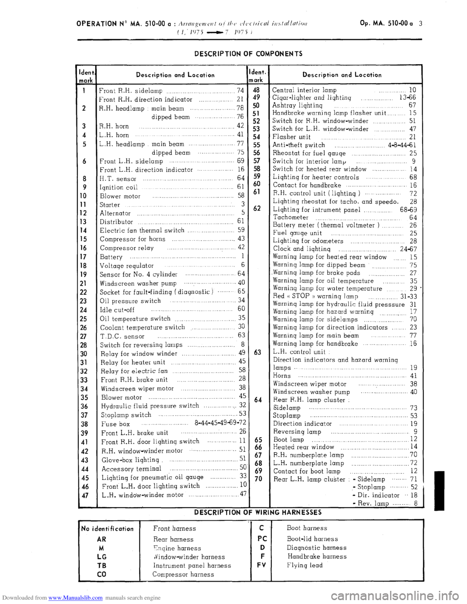
Downloaded from www.Manualslib.com manuals search engine OPERATION N” MA. 510-00 a : Arrnr~g(,v~ ('I, I 0 / Ih CJ c~lvclric-cil irtslnllc7liori Op. MA. 510-00 a 3
(I.‘1975 -7 1975 J
-
den{
lark
i
6
8
9
0
1
2
3
4
5
6
7
8
9
!l
!2
!3
!4
!5
!6
!7
!8
$0
)l
12
33
34
35
36
37
38
39
41
42
43
44
45
46
47
- DESCRIPTION OF COMPONENTS
Description and Location
‘ront R.H. sidelamp ................................... 74
‘rant R.H. direction indicator .................. 21
1.H. headlamp main beam ................. ..... 78
dipped beam ... .................. 76
3.H. horn 42 .............................................
,.H. horn ....................... ............. ............. 41
,.H. headlamp main beam .......................
77
dipped beam .................... 75
‘rant L.H. sidelamp .........
........................
69
:ront L.H. direction indicator .................. 16
I.T. sensor ............................................ 64
qnition coil ..............................................
61
3lower
motor .........................................
58
;tarter ...................................................... 3
Alternator ..................................................... 5
Xstributor 61 ...................................................
7lectric fan thermal switch .........................
59
Zompressor for horns ................................. 43
Compressor relay ..... .................
.............. 42
3attery ........... ...............................................
1
Joltaqe regulator ....................... ............. 6
jacket for fault-finding ( diagnosfic) ....... 65
3il pressure switch .... ....................... ... 34
:dle cut-off ........................................... 60
3il temperature switch
35 .............................
Coolant temperature switch ....................... 30
T.D.C. sensor ......................................... 63
Switch for reversing lamps .......................... 8
Relay for window winder ............................. 49
Relay for heater unit 45
................... ..............
Relay for electric fan 58 ..................................
Front R.H. brake unit 28 ...............................
Windscreen wiper motor .............................. 38
Blower motor ................................................ 45
Hydraulic fluid pressure switch ................... 32
Stoplamp switch ........................................... 53
Fuse box ..... .................... 8-44-45-49-69-72
Front L.H. brake unit ........................... ... 26
Front R.H. door lighting switch ... ............
11
R.H. window-winder motor .......................... 51
Glove-box lighting ....................................... 51
Accessory terminal ......................................
5c
Lighting for pneumatic oil gauge .............. 3:
Front L.H. door lighting switch
.................. I[ L.H .
window-winder motor ........................... .47 DESCRIPTION C
No identification
AR
M
LG
TB
co
Front harness
Rear harness
Ynqine harness
dindow-winder harness
Instrument panel harness
Compressor harness jent.
/ark
4”9 50
51
52
53
54
55
56
57
58
59
60
61
62
63
64
iz
67
68
69
70 Description and Location Central interior lamp ............ 10
Cigar-liqhter and lighting
.............. 13-66
Ashtray liqhtinq ...................................
67
Handbrake warning lamp flasher unit
........ 15
Switch for R.H. window-winder
.............. 51
Switch for L.H. window-winder ................ 47
Flasher unit .............................................. 21
Anti-theft switch ......................... 4-8-44-61
Rheostat for fuel qauqe ............................ 25
Switch for interior lamp ... ....................
9
Switch for heated rear window ...................
14
Liqhting for heater controls ..................... 68
Contact for handbrake
............................... 115
R.H. control unit ( liqhtinq )
................... 72
Lighting rheostat for tacho. and speedo.
28
Lighting for intrument panel ................ 68-69
Tachometer
............................................ 64
Battery meter (thermal voltmeter )
.......... 26
Fuel gauge unit
..... ....... ....... ................ 25
Lighting for odometers
....... ......... .......... 28
Clock and lighting ................................ 24-67
Warning lamp for heated rear window
15 .......
Warning lamp for dipped beam 75
_, .................
Warninq lamp for brake pads ................... 27
Warninq lamp for oil temperature
............ 35
Warning lamp for water temperature
.......... 29
Red u STOP 1) warninq lamp
............... 31-33
Warninq lamp for hydraulic fluid presssure 31
Warninq lamp for hazard warning
17
...............
Warninq lamp for sidelamps .................... 70
Warning lamp for direction indicators ...... 23
Warninq lamp for main beam ................. 77
Warning lamp for handbrake
..................... 16
L.H. control unit
Direction indicators and hazard warning lamps .........................................................
19
Horns .......................................................... 41
Windscreen wiper motor ....... .................. 38
Windscreen washer pump .......................... 40
Rear R.H. lamp cluster
Sidelamp ...................................................
73
Stoplamp ....................... .............................. 53
Direction indicator ......................................
19
Reversing lamp ....................... .............
9
Boot lamp ................................................... I2
Heated rear window 14 .....................................
R.H. numberplate lamp ...............................
70
L.H. numberplate lamp ...........
.................... 72
Contact for boot lamp .............................
12
Rear L.H. lamp cluster - Sidelamp
........ 71
,- Stoplamp
.......... 52
- Dir. indicator .. 18
- Rev. lamp ......... 8
IG HARNESSES
Boot harness
Boot-lid harness
Diagnostic harness
Handbrake harness
Flying lead
Page 308 of 394
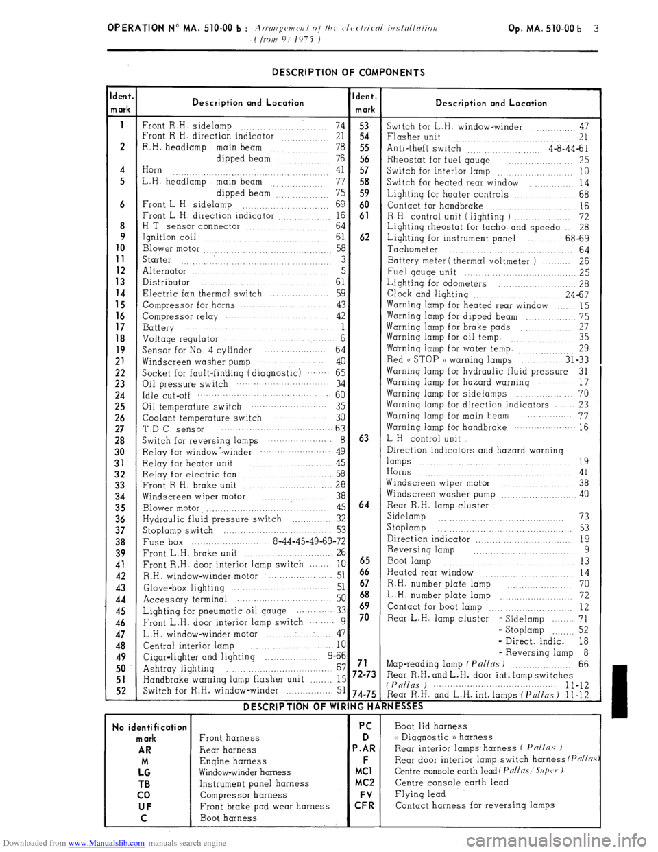
Downloaded from www.Manualslib.com manuals search engine DESCRIPTION OF COMPONENTS
dent.
Ident.
Description ond Location
n ark Description and Location
mark
1
Front R.H sidelamp
74 53
Switch for L.H. window-winder .,, 47
Front R H direction indicator
21 54 Flasher unit
.... 21
2 R.H. headlamp
main beam
78 55 Anti-theft switch
4-a-44-61
dipped beam
76 56 Rheostat for fuel gauqe
,.. 25
4 Horn
41 57
. Switch for interior lamp .,. 10
5 L.H headlamp main beam
.., .., ,.. 77 58
Switch for heated rear window
14
dipped beam”: 75 59 Lighting for heater controls _.. 68
6 Front L H sidelamp
.,. 69 60
Contact for handbrake .._....
16
Front L.H. direction indicator ,.... ._. _._.. 16 61
8 R.H control unit (lighting )
72
H T
sensor connector ,. 64
Lighting rheostat for tacho and speed0
28
9
Ignition coil ,.,
61 62 Lighting for instrument panel 68-69
10
Blower motor 58
Tachometer
.,.
64 11
Starter 3 Battery meter ( thermal voltmeter ) 26 12 Alternator ..I
5
Fuel gauqe unit 25 13
Distributor
61 14 Lighting for odometers _. 28 Electric fan thermal switch 59
Clock and lighting .._.. .,. 24-67
15
Compressor for horns 43 Warning lamp for heated rear window
15 16 Compressor relay 42 Warning lamp for dipped beam
_.. 75 17
Battery 1 Warninq lamp for brake pads 27 18 Voltage regulator . . . . . . . . . . 6 Warning lamp for oil temp. ,,_.. 35
19
Sensor for No 4 cylinder
64 Warning lamp for water temp. ..._.,,, ,,,,. 29 21
Windscreen washer pump ... .. ......
40 Red (( STOP )) warning lamps
31-33 22
Socket for fault-finding (diagnostic) .‘.‘.... 65 Warninq lamp for hydraulic fluid pressure
31 23
Oil pressure switch 34 Warning lamp for hazard warning
17 24 Idle cut-off .._........ 60
Warning lamp for sidelamps
70 25
Oil temperature switch 35 Warning lamp for direction indicators 23 26
Coolant temperature switch 30 Warninq lamp for main beam .‘..... 77 27 ‘I’D f-, SenSOr 63
Warning lamp for handbrake ... .‘........-.. 16 28
Switch for reversinq lamps ... ... ....... 8 63 L H control unit 30
Relay for window -winder ... ... .‘........ 49 Direction indicators and hazard warning 31
Relay for heater unit 45 lamps .,. .,...._ .,. .._ 19
.,. .._.......... 32
Relay for electric fan 58 Horns 41 33
Front R H. brake unit
.._.. 28 Windscreen wiper motor
..,.... 38 34
Windscreen wiper motor
_.............. 38 Windscreen washer pump
.._...... 40 35
Blower motor, ,._..._._....._._..._........ 45 64 Rear R.H. lamp cluster 36
Hydraulic fluid pressure switch _..._......... 32 Sidelamp .._...... 73
37
Stoplamp switch 53 S toplamp
_. _. _. _. _. _. _. 53
.._..............
38
Fuse box 8-44-45-49-69-72 Direction indicator
19
_.. _._.. 39
Front L.H. brake unit
. .._.._............... 26 Reversing lamp 9 41
Front R.H. door interior lamp switch 10
6665 Boot lamp .._. ._. 13
42
R.H. window-winder motor ..- 51 Heated rear window
14 43
Glove&or lightinq .._............ 51 67 R.H. number plate lamp 70
44
Accessory terminal 50 68 _..,......... L.H. number plate lamp
72 45
Lighting for pneumatic oil qauge 33 h9 Contact for boot lamp .._.. .._. .._........ 12 46
Front L.H. door interior lamp switch 9 70 Rear L.H. lamp cluster
- Sidelamp
71 47
L.H. window-winder motor ..: 47 - Stoplamp .._._... 52
48
Central interior lamp
10 - Direct. indic. 18 49
Cigar-lighter and lighting 9-66 - Reversing lamp 8
.._....
50 Ashtray lighting 67 71 Map-reading lamp f Pnl/ns ) .._..._....._.
66
_._......._...................... 51
Handbrake warning lamp flasher unit .._._.._ 15 72-73 Rear R.H. and L.H. door int. lamp switches 52
Switch for R.H. window-winder _..._.. 51 (P(/llgs ) 1 l-12 74-75 Rear R.H. and L.H. int. lamps ( f’nlins ) 1 l-12 DESCRIPTION OF WIRING HARNESSES
No identification PC
Boot lid harness mark
Front harness D <( Diagnostic )) harness AR
Rear harness P.AR Rear interior lamps.harness f I’n//nc )
M Engine harness F
Rear door interior lamp switch harness (Pflj/~.s LG
Window-winder harness MC1 Centre console earth lead( Pall~.~,’ S~/jczr ) TB
Instrument panel harness MC2 Centre console earth lead
co Compressor harness Flying lead UF
Front brake pad wear harness C: Contact harness for reversing lamps
C Boot harness
Page 313 of 394
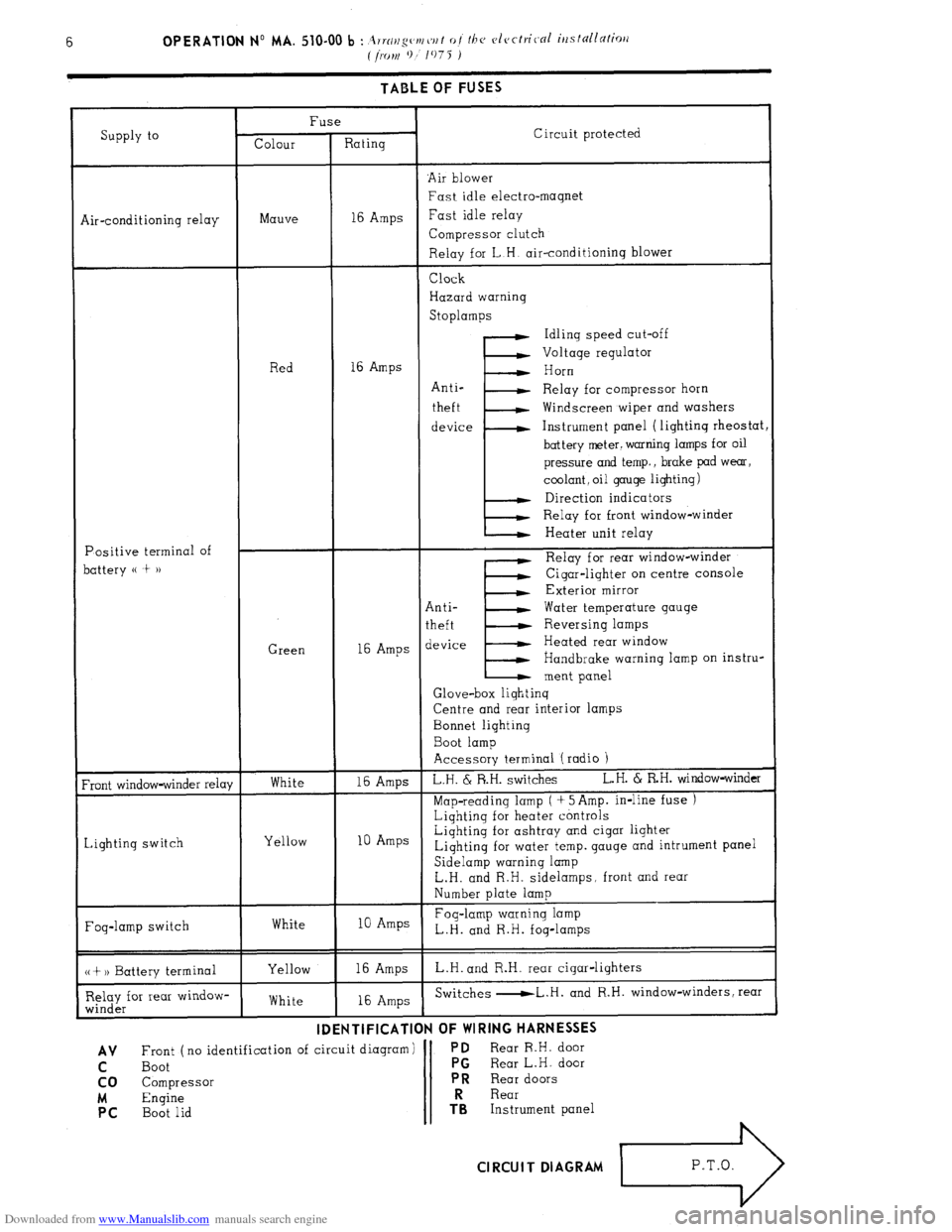
Downloaded from www.Manualslib.com manuals search engine TABLE OF FUSES
Supply to Fuse
Colour Rating Circuit protected
‘Air blower
Fast idle electro-magnet
Air-conditioning relay Mauve 16 Amps Fast idle relay
Compressor clutch
Relay for L.H. air-conditioning blower
Positive terminal of
battery (( t )) Red
Green Clock
Hazard warning
Stoplamps
Idling speed cut-off
Voltage regulator
16 Amps
I’ Horn
Anti-
Relay for compressor horn
theft Windscreen wiper and washers
device Instrument panel (lighting rheostat
battery meter. warning lamps for oil
pressure and temp., brake pad wear,
coolant, oil gauge lighting)
Direction indicators
Relay for front window-winder
Heater unit relay
E Relay for rear window-winder
Cigar-lighter on centre console
Exterior mirror
Anti- Water temperature gauge
theft Reversing lamps
16 Amps device Heated rear window
Handbrake warning lamp on instru-
ment panel
Glove-box lighting
Centre and rear interior lamps
Bonnet lighting
Boot lamp
Accessory terminal (radio 1
Front window-winder relay
Lighting switch White
Yellow 16 Amps L.H. & R.H. switches L.H. 6 RH. window-winder
Map-reading lamp ( + 5Amp. in-line fuse )
Lighting for heater controls
10 Amps Lighting for ashtray and cigar lighter
Lighting for water temp. gauge and intrument panel
Sidelamp warning lamp
L.H. and R.H. sidelamps. front and rear
Number plate lamp
Fog-lamp switch White 10 Amps Fog-lamp warning lamp
L.H. and R.H. fog-lamps
(( + 1) Battery terminal
Relay for rear window-
winder Yellow
White 16 Amps L.H. and R.H. rear cigar-lighters
16 Amps Switches -L.H. and R.H. window-winders, rear
-.. -- . ..-...- . . . -..---m-
IDENTIFICATION
OF WIRING HARNt33t3
AV Front ( no identification of circuit diagram) PD Rear R.H. door
C Boot PG
Rear L.H. door
co Compressor PR
Rear doors
M Engine Rear PC
Boot lid TRS Instrument panel Cl RCUI T DIAGRAM
L3
P.T.O.