Temperature Citroen CX 1984 1.G Service Manual
[x] Cancel search | Manufacturer: CITROEN, Model Year: 1984, Model line: CX, Model: Citroen CX 1984 1.GPages: 394
Page 366 of 394
Downloaded from www.Manualslib.com manuals search engine Operating principle :
Both electric fans ( 12) and ( 14) cool the engine coolant in the radiator. Electric fan ( 14) cools the condenser
when the compressor expels the air-conditioning cooling fluid under pressure.
Simultaneous supply to fans (12) and (14) :
This is carried out by means of contacts in relays ( 1 ) and ( 9). The fl ow of current in the energizinq winding of
relays ( 1 ) and ( 9) therefore operates both electric fans simultaneously.
The relay windings are supplied when
- ignition is switched on
*
thermal switch ( 13) controlled by the coolant temperature in the radiator is off. _-
Supply to supplementary electric fan ( 14) alone :
This is carried out by contacts in relay ( 8) when its energizing winding is supplied
The relay winding is supplied when
- ignition is on
- air-conditioning switch ( 4) is off
a
contact on the ambient temperature thermostat ( 3) is closed.
Supply to the electro-magnetic clutch for the compressor :
The clutch supply is a function of the following
- Air-conditioning switch (4)
- Ambient temperature thermostat ( 3 )
-
High pressure switch ( 5).
Supply to the blower ( 15) :
This is carried out by resistors ( 16) of the rheostat. This rheostat controls the speed of the blower ( 3-speed )
and consequently, the volume of displaced air.
Page 374 of 394
Downloaded from www.Manualslib.com manuals search engine OPERATION No MA. 640-O : C h
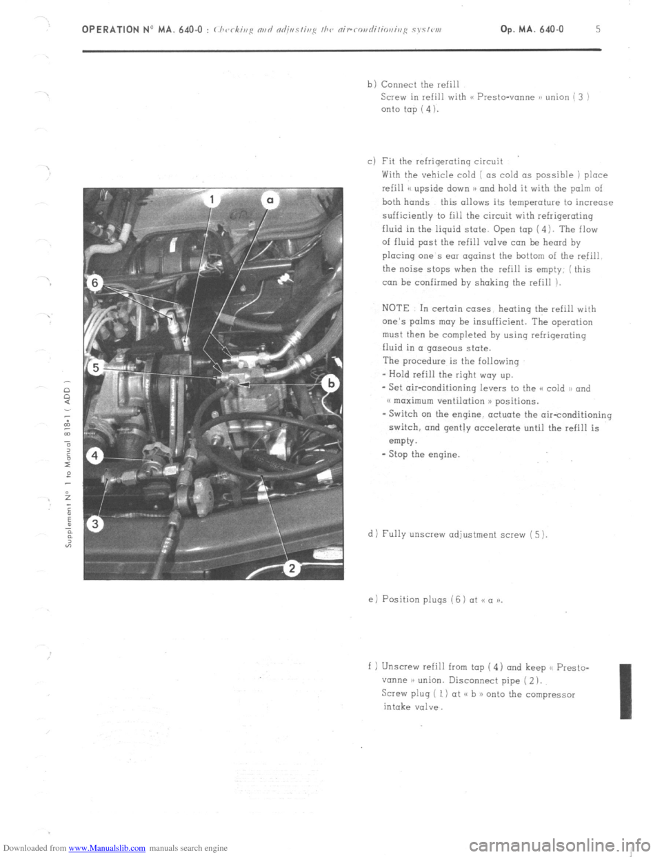
Screw in refill with (< Presto-vonne ~1 union ( 3 )
onto top (4).
c) Fit the refrigerating circuit
With the vehicle cold ( as cold as possible 1 place
refill << upside down >B and hold it with the palm of
both hands this allows its temperature to increase
sufficiently to fill the circuit with refrigerating
fluid in the iiquid state. Open top (4). The flaw
of fluid post the refill valve can be heard by
placing one s ear against the bottom of the refill
the noise stops when the refill is empty; ( this
can be confirmed by shaking the refill ).
NOTE In certain cases heating the refill with
one’s palms may be insufficient. The operation
must then he completed by using refrigerating
fluid in a gaseous state.
The procedure is the following
- Hold refill the right way up.
- Set air-conditioning levers to the SC cold )B and
(( maximum ventilation )) positions.
- Switch on the engine, actuate the air-conditioning
switch, and gently accelerate until the refill is
empty.
- Stop the engine.
d) Fully unscrew adjustment screw (5 ).
e) Position plugs ( 6 ) ot SC a )).
f 1 Unscrew refill from tap (4 1 and keep << Presto-
vanne )a union. Disconnect pipe ( 2 ).
Screw plug ( 1) at ,< h 1) onto the compressor
intake valve.
Page 376 of 394
Downloaded from www.Manualslib.com manuals search engine Op. MA. 642-00
(< FROID - 20 n HEATING SYSTEM
This heating system consists of the following :
- A device to heat the inlet air
- A’device to increase the heating in the passenger compartment
- A water temperature gauge
- The crankcase has a plug which can be removed to allow a heating element to be inserted in order
to heat the engine coolant
Page 379 of 394
Downloaded from www.Manualslib.com manuals search engine B. THERMAL SENSOR
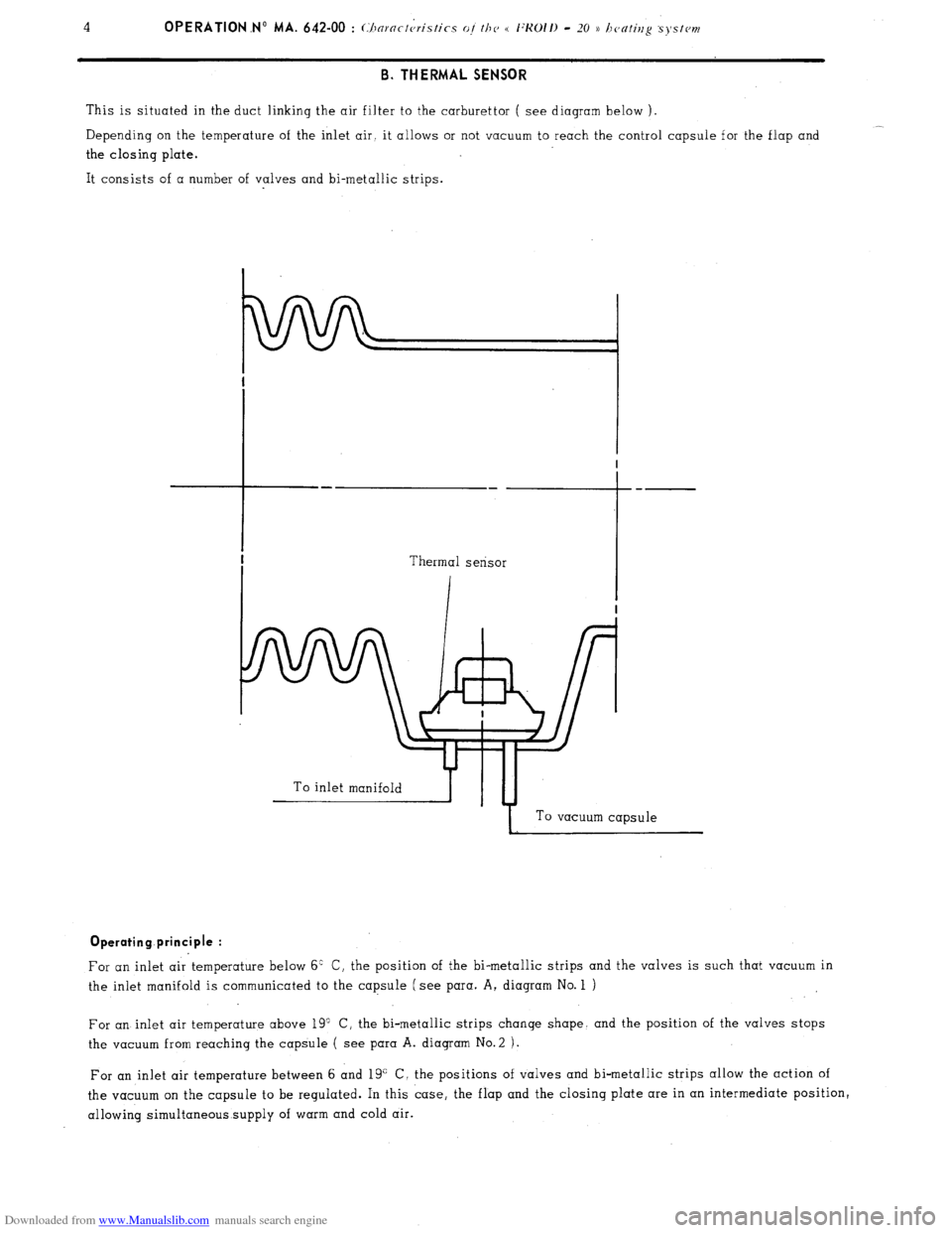
This is situated in the duct linking the air filter to the carburettor ( see diagram below ).
__
Depending on the temperature of the inlet air. it allows or not vacuum to reach the control capsule for the flap and
the closing plate.
It consists of a number of valves and bi-metallic strips.
To inlet manifoldb-yTu-4
I To vacuum capsule Operating principle :
For an inlet air temperature below 6’ C, the position of the bi-metallic strips and the valves is such that vacuum in
the inlet manifold is communicated to the capsule (see para. A, diagram No. 1 )
For an inlet air temperature above 19” C, the bi-metallic strips change shape. and the position of the valves stops
the vacuum from reaching the capsule ( see para A. diagram No.2 ).
For an inlet air temperature between 6 and 19” C, the positions of valves and bi-metallic strips allow the action of
the vacuum on the capsule to be regulated. In this case, the flap and the closing plate are in an intermediate position,
allowing simultaneous supply of warm and cold air.
Page 380 of 394
Downloaded from www.Manualslib.com manuals search engine Op MA. 642-00 5 II. DEVICE FOR INCREASING THE HEATING OF THE PASSENGER COMPARTMENT
This device entails modifying the following components
- Heater distribution box ( outlets towards side vents unplugged, different radiator )
Side vents with twin outlets ( ambient or heated air )
Addition of Westaflex ducts ( link from heater distribution box to side vents ). III. WATER TEMPERATURE GAUGE
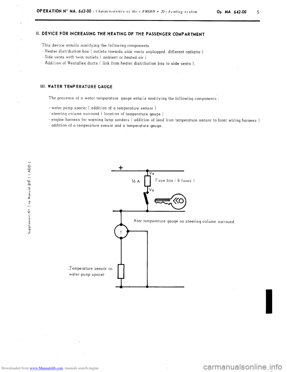
The presence of a water temperature gauge entails modifying the following components :
- water pump spacer ( addition of a temperature sensor )
steerinq column surround ( location of temperature gauqe )
- engine harness for warning lamp senders ( addition of lead from temperature sensor to front wiring harness )
addition of a temperature sensor and a temperature gauge.
Ater temperature gauge on steering column surround
.Temperature sensor on
water-pump spacer
P
Page 389 of 394
Downloaded from www.Manualslib.com manuals search engine OPERATION No MA. 961-O : C/ 3fc ztzg and repairing a war winabzc’ hrating elcmcnt k’ Op. MA. 961-O 1
I. CHECKING
Power of heating resistance :
S&Ions ., 140 to 160 watts at 13.5 1: 0.2 volts
Estates .,.,............: . . . . . . . .._.... . . . . . . . . . . . . . . . . . . . . . . . . . . . . . . . . . . . . . . . . . . . . . . . . . . . . . . . ~.. 130 to 150 watts at 13.5 t 0.2 volts
To check :he heating resistance of a rear window. measure
Either the current flowing in the resistance, using an ammeter connected in series to the supply lead of
the element. The current should be :
Saloons ,..., ., ,. ,. ,..,. ,,., ,,,., _, ,. .,., ..l_. 9.2 to 10.6 amps at 12 volts
Estates . . .., ,,..._.__.. .:_._ ._ . ..8 5 to 9.8 amps at 12 volts
Or the resistance using an ohmmeter. Resistance should be :
Saloons . . . . . . . . . . . . . . . . . . . . . . . . . . . . . . . . . j _..__.._....,. 1.1 to 1.3Q
Estates . .._...........,.,.,...,.....,..,..................................,,..,.,.,.,........,. 1 .2 to 1.4 !J
II. REPAIRING
1. Replacement of terminals : Tin that part of the terminal to be soldered. Solder it in the required location ( soldering iron ).
2. Repairing a section of the heating element : a) Obtain from the Replacement Parts Department :
- 1 Repair kit .,,..,,..,,.,.,.,.,,,.,.,,....,................,,,,,...,., ZC. 9 855 128 U
This M SECURIGLACE ))‘outfit includes :
- 1 Bottle of abrasive cleaning powder
- 1 Small bottle of conductive enamel
- 1 Tube of adhesive
- 1 Tube of hardener for adhesive
- 1 Small bottle of metallic powder
- 1 Roll of thick self-adhesive tape
- 1 Warning lamp for detecting cuts
- 1 Roll of self-adhesive tape for detecting cuts ( thermopaper )
- 1 Plastic spatula
- 1 Small glass plate ( for preparation of mixtures )
b)
Locating the cut : With the resistance fed as normal :
- Locate the defective resistance wire by sticking the adhesive detection tape at the centre of the rear
window ( interior side ) and on all resistance wires so that the tape is perpendicular to the latter.
The unbroken wires will turn the thermo-paper blue when they increase in temperature.
- Slide the two pointed probes of the warning lamp support on the cut wire. When the lamp lights up,
the pointed probes are on both sides of the break in the wire.
By slightly moving the probes along the length of the wire, the exact extent of the cut can be determined.
Page 390 of 394
Downloaded from www.Manualslib.com manuals search engine C) Preparing the rear window :
With the resistance switched off, clean the area to be treated with the powder contained in the bottle marked
(( Bimspulver )L
Spread this product on a small piece of cloth and rub.
Wipe off with a second clean cloth.
Place a strip, 25 mm long, of thick adhesive tape on each side of the resistance to mark out the width of the
resistance. The edges of the strip must be perfectly straight and clean so
as to avoid the possibility of a
cut during repair.
d
) Rep’ai r operation :
Zst part.
Empty the complete contents of the bottle of conductor enamel onto the glass plate. Mix thoroughly with the
spatula.
Apply the paste thus obtained on the area required,,filling the space between the two adhesive tapes.
Restrict the application of paste to the cut area.
Allow to dry at ambient temperature for approximately 15 minutes.
2nd Part
On the glass plate, prepare a small quantity of mixture composed of equal parts of UHV hardener and binding
agent.
Add to this paste an equal quantity of the metallic powder contained in the bottle marked (( Metallpulver )).
Mix well, using the spatula.
Apply the resulting paste on the conductor enamel deposit, overlapping on both sides by 10 mm, but with the
width still restricted by the strips of adhesive tape.
Thickness of the mixture should be equalized with the spatula, using the tape as a support.
Allow to dry for 1 l/2 hours at ambient temperature before removing the strips of adhesive tape.Move them aside
in a parallel direction to the surface of the rear window to avoid removing the applied film. Drying time can be
reduced by passing electric current through the resistance for half an hour.
NOTE : Wait for 24 to 48 hours before cleaning the inside of the rear window.
e) Checking :
The check can be carried out using the self-adhesive detecting tape.
Proceed as when locating the cut.