circuit diagram Citroen CX 1985 1.G Owner's Manual
[x] Cancel search | Manufacturer: CITROEN, Model Year: 1985, Model line: CX, Model: Citroen CX 1985 1.GPages: 394
Page 330 of 394

Downloaded from www.Manualslib.com manuals search engine OPERATION No MA. 510-00 b : , ,rn,l~~~‘Nl(‘Il I 0 / Ill C’ c~/~~tl,.ifNI ir/.YlnllalitM/
( j,arv 9 107j I
. Op. MA. 510-00 b
15
CIRCUIT DIAGRAM
Page 331 of 394

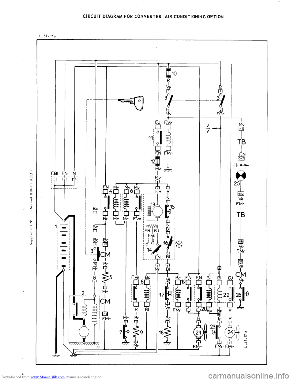
Downloaded from www.Manualslib.com manuals search engine CIRCUIT DIAGRAM FOR CONVERTER -AIR-CONDITIONING OPTION
L.Sl-170
Page 339 of 394

Downloaded from www.Manualslib.com manuals search engine 20 OPERATION No MA. 510-00 b : Ivstallatiov oj the c,lcctriral iv~stallatiov
( [KM 9 / I 07 5 )
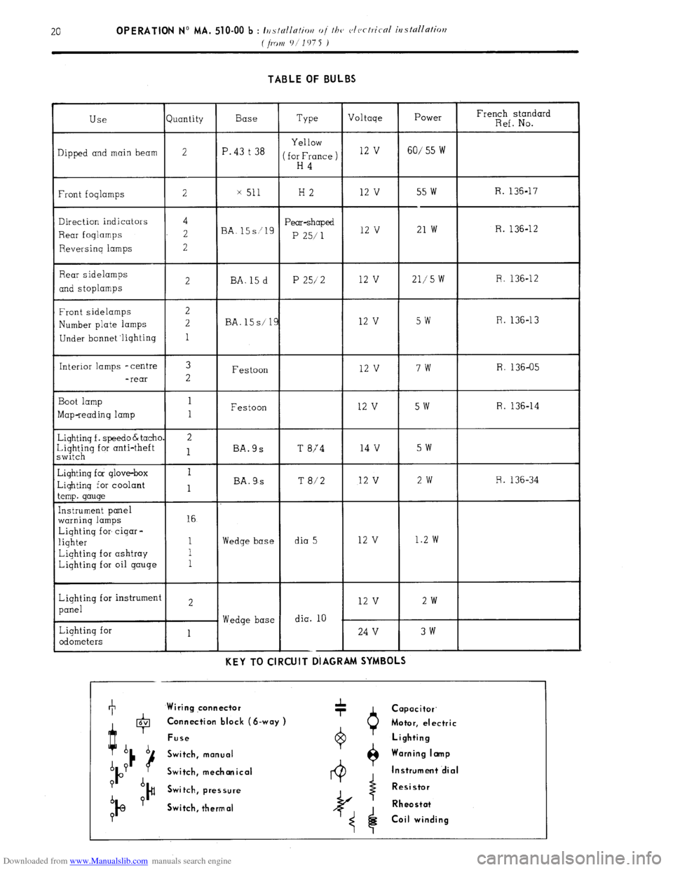
TABLE OF BULBS
juantity Type French standard
Ref. No. Power
60/ 55 W Voltage
12 v Base
P. 43 t 38 Use
lipped and main beam
Front foqlamps
Direction indicators
Rear foqlamps
Reversinq lamps
Rear sidelamps
and stoplamps
Front sidelamps
Number plate lamps
Under bonnet ‘lighting
Interior lamps -centre
-rear
Boot lamp
Map-reading lamp
&iqhtinq f . speed0 & tachl
~~$;~q for anti-theft
diqhtinq for glove-box
-iqhtinq for coolant
.emp. gauge
[nstrument panel
warning lamps
Lighting for cigar -
lighter
Lighting for ashtray
Lighting for oil gauge
Lighting for instrumen
panel
Lighting for
odometers Yellow
for France )
H4 2
x 51 H2 12 V 55 w
--
21 w R. 136-17
4
2
2 Pear-shaped
P 25/ 1 R. 136-12
BA. 12 v
12 v 21,‘5 W R. 136-12
2 BA. 15 d P 25/2
R. 136-13
BA. 15s/ 5w
7w
5w
5w 12 v
12 v
12 v
14 v 3
2 R. 136-05
Festoon
Festoon
BA.9s
T 874 R. 136-14 1
1
2
1
T 8/2 12 v 2w R. 136-34
BA. 9,s
16
Wedge base dia 5 12 v 1.2 w
Wedge base dia. 10 2w 12 v
24 V 3w
1 --
KEY TO CIRCUIT DIAGRAM SYMBOLS +
Wiring qonnector
0 Capacitor.
4 6V Connection block (S-way )
Motor, electric
Fuse Lighting
b b
Switch, manual Warning I amp
A P
P u
Switch, mechanical Instrument .dial
P A
)# Switch, pressure Resistor
b P
IQ Switch, thermal Rheostat
?
Coil winding
Page 359 of 394

Downloaded from www.Manualslib.com manuals search engine OPERATION No MA. 560.0 : ~hrrkin~ o,,d oc/@s/i,,g I/><, wiurisrrrr,, wip’r. Op. MA. 560.0
1
Fi
m
0 CHECKING AND ADJUSTING THE WINDSCREEN WIPER.
FRONT WINDSCREEN WIPER MOTOR
CHARACTERISTICS.
Manufacturer DUCELLIER
Reference No. 4966 A
Field coils Ferrite
Armature : Endfloot (adjustable by means of stop-screw) : 0.2 mm
Nominal dia. of commutator :
24 mm
Min. dia. after machining : 23 mm
Brushes : Ref. No. :
CL 7239
Minimum length after wear : 5.5 mm
Ratio : .._...................................................................................................
44 1
Connection and circuit diagram as in Op. MA. 510 00.
ELECTRICAL CHECK. BOSCH
0390 346 127
Ferrite
0
23.2 mm
23 mm
1.394.320-058 059, 062
7.5 mm
49 1
1. First speed :
Nominal power : IO watts
Speed, under no load, at 13.5 volts = 50 rpm Corresponding current = I.8 A
Torque, motor locked, at 13.5 volts = 1.9 da Nm 7 13.74 ft.lb min. Corresponding current 18 A max.
Torque at 40 rpm and 13.5 volts = 0.2 do Nm (1.45 ft.lb) Correspondinq current = 5.5 A max.
- Torque ot 20 rpm and 13.5 volts = 1.07 da Nm (7.74 ft.lb) min Corresponding current = 13.2 A max.
2. Second speed :
Nominal power : 15 watts
Speed under no load at 13.5 volts = 70 rpm Corresponding current = 2.3 A
Torque motor locked at 13.5 volts = 1.5 do Nm (IO.85 ft.lb) min Corresponding current = 21 A max
Torque at 60 rpm and 13.5 volts = 0.2 da Nm (1.45 ft.lb) min Corresponding current = 7 A max
Torque ot 30 rpm and 13.5 volts = 0.9 da Nm (6.51 ft.lb) min Corresponding current = 14.7 A mrx.
ADJUSTMENT OF WINDSCREEN WIPER ARM
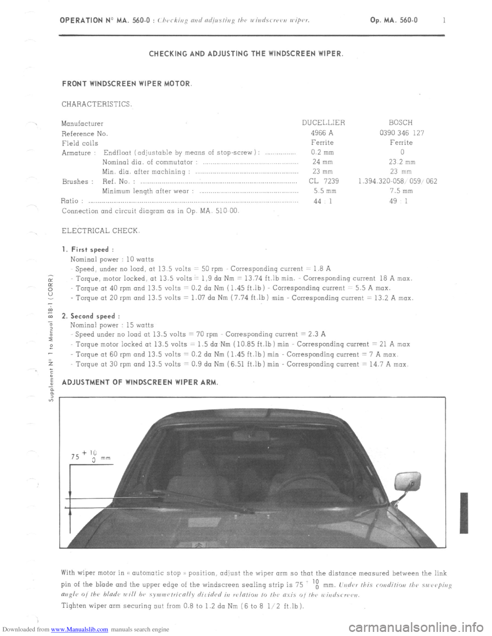
With wiper motor in (< automatic stop )/ position, adjust the wiper arm so that the distance measured between the link
pin of the blade and the upper edge of the windscreen sealing strip is 75 ‘t
mm. L’vd‘ar /his rondiliw, /he 51, rvp;,,g
m,g/r 0, /he bladr ,,~i// hv symv,r~/rirn//v dil idrd it, w/n/io,, 10 /he O.YiS “, I/w r,‘iri
Tighten wiper arm securing out from 0.8 to 1.2 da Nm (6 to 8 l/2 ft.lb).