starter Citroen CX 1985 1.G Workshop Manual
[x] Cancel search | Manufacturer: CITROEN, Model Year: 1985, Model line: CX, Model: Citroen CX 1985 1.GPages: 394
Page 41 of 394
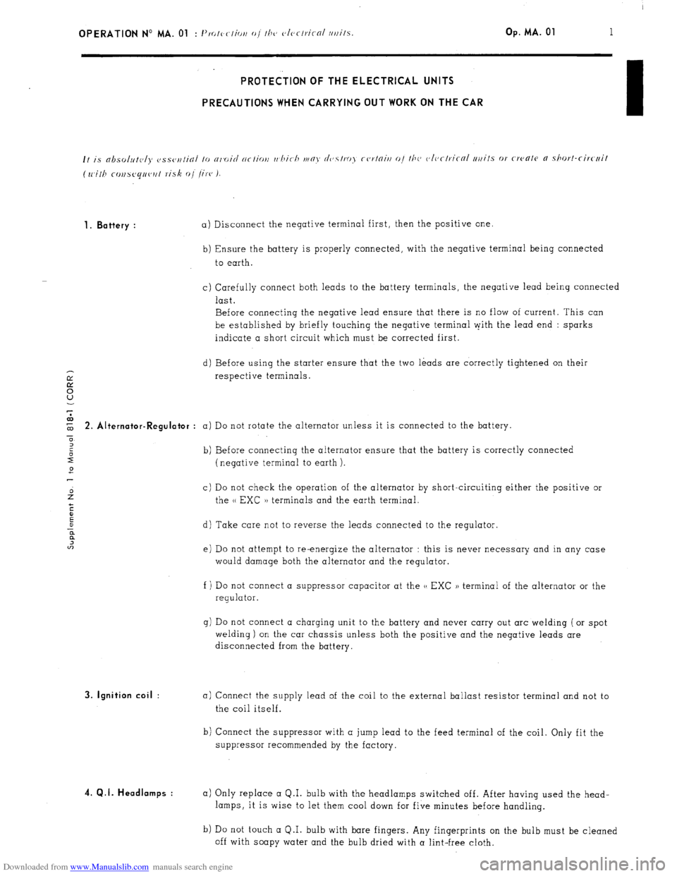
Downloaded from www.Manualslib.com manuals search engine OPERATION No MA. 01 : 1’. I, -1’ IO c ( lOi, o/ I/J<, c~lcrlricnl /l/lilS. Op. MA. 01 1 PROTECTION OF THE ELECTRICAL UNITS
PRECAUTIONS WHEN CARRYING OUT WORK ON THE CAR
1. Battery :
a) Disconnect the negative terminal first, then the positive one.
b) Ensure the battery is properly connected, with the negative terminal being connected
to earth.
c) Carefully connect both leads to the battery terminals, the negative lead being connected
last.
Before connecting the negative lead ensure that there is no flow of current. This can
be established by briefly touching the negative terminal pith the lead end : sparks
indicate a short circuit which must be corrected first.
d) Before using the starter ensure that the two leads are correctly tightened on their
respective terminals. $ 2. Alt ernator-Regulator :
a) Do not rotate the alternator unless it is connected to the battery.
0
2
2 b) Before connecting the alternator ensure that the battery is correctly connected
2 (negative terminal to earth ).
c) Do not check the operation of the alternator by short-circuiting either the positive or
the u EXC )) terminals and the earth terminal.
d) Take care not to reverse the leads connected to the regulator.
e) Do not attempt to re-energize the alternator : this is never necessary and in any case
would damage both the alternator and the regulator.
f ) Do not connect a suppressor capacitor at the u EXC )) terminal of the alternator or the
regulator.
g) Do not connect a charging unit to the battery and never carry out arc welding ( or spot
welding) on the car chassis unless both the positive and the negative leads are
disconnected from the battery. 3. Ignition coil :
4. Q.I. Headlamps :
a) Connect the supply lead of the coil to the external ballast resistor terminal and not to
the coil itself.
b) Connect the suppressor with a jump lead to the feed terminal of the coil. Only fit the
suppressor recommended by the factory.
a) Only replace a Q.I. bulb with the headlamps switched off. After having used the head-
lamps, it is wise to let them cool down for five minutes before handling.
b) Do not touch a Q.I. bulb with bare fingers. Any fingerprints on the bulb must be cleaned
off with soapy water and the bulb dried with a lint-free cloth.
Page 66 of 394
Downloaded from www.Manualslib.com manuals search engine OPERATION No MA. 100-00 : Characteristics and special features of the engine. Op. MA. 100.00 15
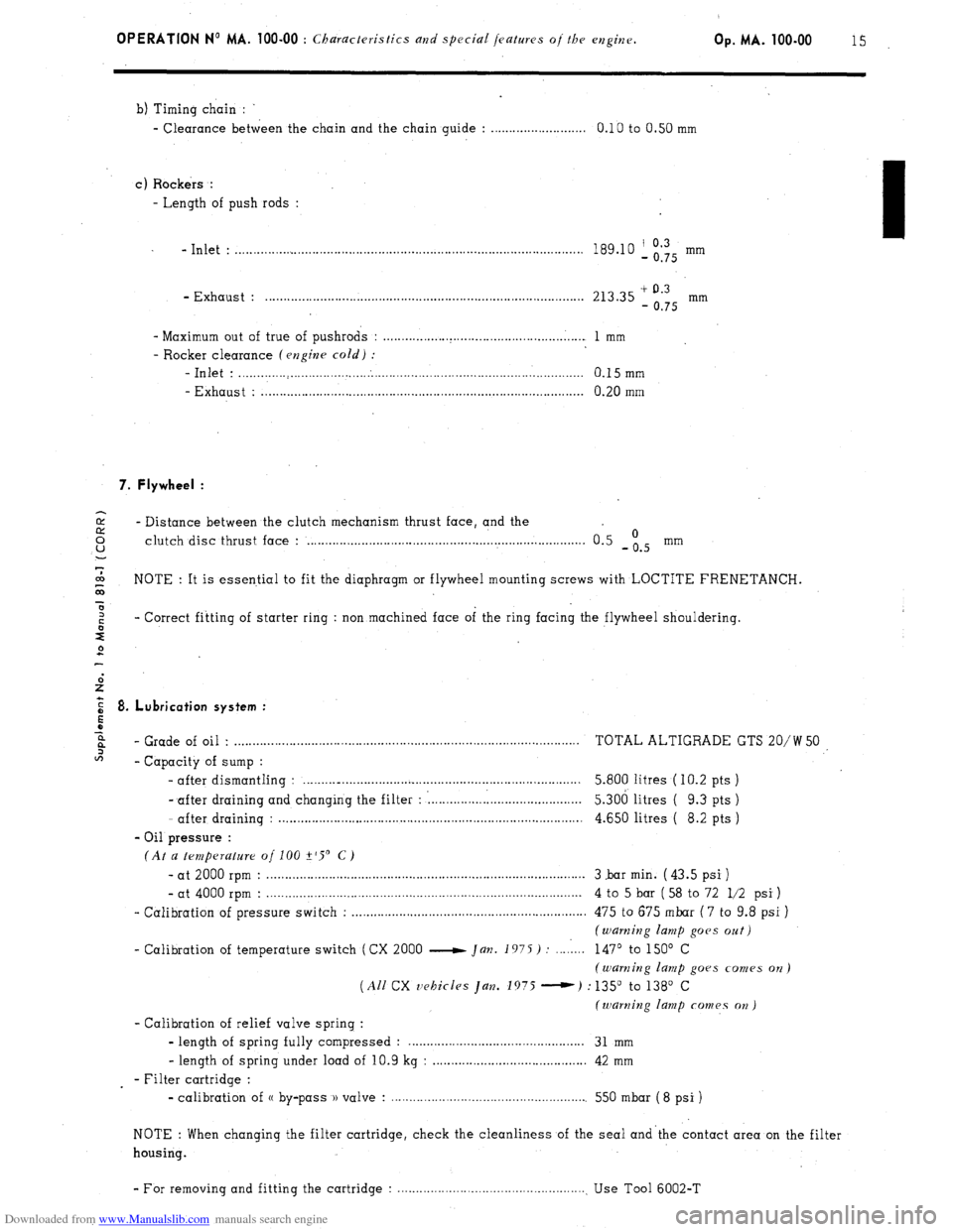
b) Timing chain :
- Clearance between the chain and the chain guide : . . . . . . . . . . . . . . . . . . . . . . . . . . 0.10 to 0.50 mm
c) Rockers :
- Length of push rods :
- Inlet : . . . . . . . . . . . . . . . . . . . . . . . . . . . . . . . . . . . . . . . . . . . . . . . . . . . . . . . . . . . . . . . . . . . . . . . . . . . . . . . . . . . . . . . . . . . . . . 189.10 ‘, Og’Q5 mm
- Exhaust : . . . . . . . . . . . . . . . . . . . . . . . . . . . . . . . . . . . . . . . . . . . . . . . . . . . . . . . . . . . . . . . . . . . . . . . . . . . . . . . . . . . . . . . 213.35 + 0.3
- 0.75 mm
- Maximum out of true of pushrods : . . . . . . . . . . . . . . . . . . . . . . . . . . . . . . . . . . . . . . . . . . . . . . . . . . . . . . . 1 mm
- Rocker clearance (engine cold) :
-Inlet : . . . . . . . . . . . . . . . . . . . . . . . . . . . . . . . . . . . . . . . . . . . . . . . . . . . . . . . . . . . . . . . . . . . . . . . . . . . . . . . . . . . . . . . . . . . . . . 0.15mm
- Exhaust : . . . . . . . . . . . . . . . . . . . . . . . . . . . . . . . . . . . . . . . . . . . . . . . . . . . . . . . . . . . . . . . . . . . . . . . . . . . . . . . . . . . . . . . . 0.20 mm
7. Flywheel :
2 - Distance between the clutch mechanism thrust face, and the 0 u clutch disc thrust face : . . . . . . . . . . . . . . . . . . . . . . . . . . . . . . . . . . . . . . . . . . . . . . . . . . . . . . . . . . . . . . . . . . . . . . . . . . . . 0.5 -is mm
7
co
G NOTE : It is essential to fit the diaphragm or flywheel mounting screws with LOCTITE FRENETANCH.
x
z - Correct fitting of starter ring : non machined face of the ring facing the flywheel shouldering.
s
2
E 8. Lubrication system :
5
z
6%
- Grade of oil . . . . . . . . . . . . . . . . . . . . . . . . . . . . . . . . . . . . . . . . . . . . . . . . . . . . . . . . . . . . . . . . . . . . . . . . . . . . . . . . . . . . . . . . . . . . . . . TOTAL ALTIGRADE GTS 20/W 50
2
- Capacity of sump :
- after dismantling : . . . . . . . .._................................................................. 5.800 litres ( IO.2 pts )
- after draining and changing the filter : : . . . . . . . . . . . . . . . l......................... 5.306 litres ( 9.3 pts )
- after draining : . . . . . . . . . . . . . . . . . . . . . . . . . . . . . . . . . . . . . . . . . . . . . . . . . . . . . . . . . . . . . . . . . . . . . . . . . . . . . . . . . . . 4.650 litres ( 8.2 pts )
- Oil pressure :
(At a temperature of 100 +‘S’ C)
- at 2000 rpm : . . . . . . . . . . . . . . . . . . . . . . . . . . . . . . . . . . . . . . . . . . . . . . . . . . . . . . . . . . . . . . . . . . . . . . . . . . . . . . . . . . . . . . . 3 .bar min. ( 43.5 psi )
- at 4000 rpm : . . . . . . . . . . . . . . . . . . . . . . . . . . . . . . . . . . . . . . . . . . . . . . . . . . . . . . . . . . . . . . . . . . . . . . . . . . . . . . . . . . . . . . 4 to 5 bar ( 58 to 72 l/2 psi )
- Calibration of pressure switch : . . . . . . . . . . . . . . . . . . . . . . . . . . . . . . . . . . . . . . . . . . . . . . . . . . . . . . . . . . . . . . . . 475 to 675 mbar ( 7 to 9.8 psi )
(warning lamp goes oat)
- Calibration of temperature switch (CX 2000 e Jan. 1975) : . . . . 1... 147’ to 150’ C
(warning lamp goes comes on)
(All CX vehicles Jan. 1975 -) : 135” to 138’ C
(warning lamp comes on )
- Calibration of relief valve spring :
- length of spring fully compressed : . . . . . . . . . . . . . . . . . . . . . . . . . . . . . . . . . . . . 31 mm
- length of spring under load of 10.9 kg : . . . . . . . . . . . . . . . . . . . . . . . . . . . . . . . . . . . . . . . . . . 42 mm
- Filter cartridge :
- calibration of (( by-pass )) valve : . . . . . . . . . . . . . . . . . . . . . . . . . . . . . . . . . . . . . . . . . . . . . . . . . . . . . . 550 mbar ( 8 psi )
NOTE : When changing the filter cartridge, check the cleanliness of the seal and’the contact area on the filter
housing.
- For removing and fitting the cartridge : . . . . . . . . . . . . . . . . . . . . . . . . . . . . . . . . . . . . . . . . . . . . . . . . . . . . Use Tool 6002-T
Page 69 of 394
Downloaded from www.Manualslib.com manuals search engine OPERATION No MA. 112-O : ChcJcking and adjusting the valrv mechanism. Op. MA. 112-O
1
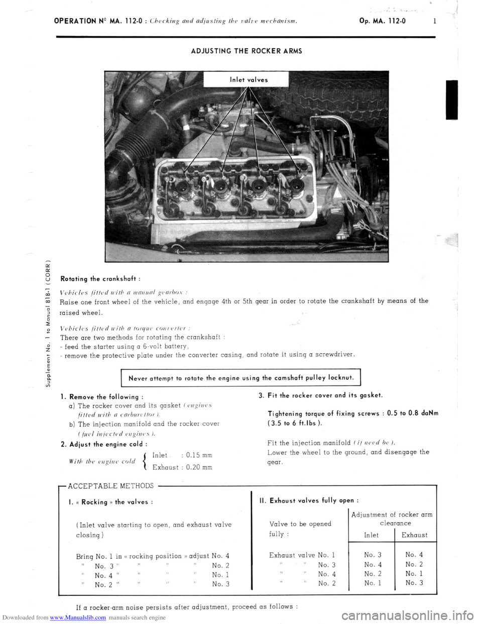
ADJUSTING THE ROCKER ARMS
Ir
E
2 Rotating the crankshaft :
7
m
Vc,birlvs /i//cd wifh n WRIINRI ~varbot :
E Raise one front wheel of the vehicle,
and engage 4th or 5th gear in order to rotate the crankshaft by means of the
3
6 raised wheel.
I
e Vchirlcs /ittcd wilh a lo~qnr covwrlc~ :
- There are two methods for rotating the crankshaft :
Gz feed the
starter using CI G-volt battery,
;
remove the protective plate under the converter casing, and rotate it using a screwdriver.
:
Never attempt to rotate the engine using the camshaft pulley locknut.
1. Remove the following :
a) The rocker cover and its gasket (~,ofii~rr~s
/i//d Will, a rarb,,wt/or I.
b) The injection manifold and the racker-cover
(/,,<,I iU/<~CfPd r,zgir,rs 1.
2. Adiust the engine cold :
Inkt : 0.15 mm
With lb<‘
3. Fit the rocker cover and its gasket.
Tightening torque of fixing screws : 0.5 to 0.8 daNm
(3.5 tc. 6 ft.lbs ).
Fit the injection manifold f i/ nczvd br 1.
Lower the wheel to the ground,
and disengage the
gear.
r ACCEPTABLEMETHODS
I I
I. (< Rocking )> the valves :
(Inlet valve starting to open, and exhaust valve
I
closing) closing)
Bring No. 1 in <, rocking position /) adjust No. 4 Bring No. 1 in <, rocking position /) adjust No. 4
II II
No. 3” ” ” ” No. 3” ” ” ” No. 2 No. 2
0 0
No.4 I’ ” ” ” No.4 I’ ” ” ” No. 1 No. 1
” No.2 ” ” ” ” ” No.2 ” ” ” ” No. 3 No. 3
II. Exhaust valves fully open :
Valve to be opened
fully : Adjustment of rocker arm
CleUKUlCe
Exhaust valve No. 1
,, I, No. 3
,, ,, No. 4
,, ,, No. 2
If a rocker-rim noise persists after adjustment, proceed as follows :
Page 71 of 394
Downloaded from www.Manualslib.com manuals search engine OPERATION No MA. 120.0 : Chrrki,,~ the /iminp. Op. MA. 120-O 1
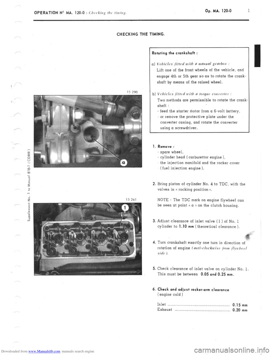
CHECKING THE TIMING.
lototing the crankshah :
) Vebirl~s /i/fed with a mantra~ gearbox :
Lift one of the front wheels of the vehicle, and
engage’ 4th or 5th gear so as to rotate the crank-
shaft,
by means of the raised wheel.
1) Vehicles /itted with n torqee ronrwrter :
Two methods are permissible to rotate the crank
shaft :
- feed the starter “iota from (I &volt battery,
or remove the protective plate under the
converter casing, and rotate the converter
using a screwdriver.
1. Remove :
spore wheel,
cylinder head (carburettor engine 1,
the injection manifold and the rocker cover
(fuel injection engine 1.
2. Bring piston of cylinder No. 4 to TDC. with the
valves in (( rocking position x
NOTE : The TDC mark on engine flywheel co”
be see” at point (( a )) on the clutch housing.
3. Adjust clearance of inlet valve ( 1 ) of No. 1
cylinder to
1.10 mm (theoretical clearance 1.
4. Turn crankshaft exactly one turn in direction of
rotation of engine f m/i-clockwise iro>t! /lyre hpel
side I.
5. Check clearance of inlet valve on cylinder No. 1.
This must be between 0.05
and 0.25 mm.
6. Check and adiust rocker-arm clearance
(engine cold )
Inlet .__....__.............................................,.,, 0.1 5 mm
Exhaust . . . . . . . . . . . . . . . . . . . . . . . . . . . . . . . . . . . . . . . . . . . . . . . . . . . . 0.20 mm
Page 92 of 394
Downloaded from www.Manualslib.com manuals search engine OPERATION No MA. 142-O SD : (I k’ II c ,r,g m,d or/j,,r/ii,,~ /he m/i /dllllior, 5, Cl<‘,,i Op. MA. 142-O SD 1
f SIi’III)ISH \IAKKl:‘/ ,‘1,,,( 1.1’) ,
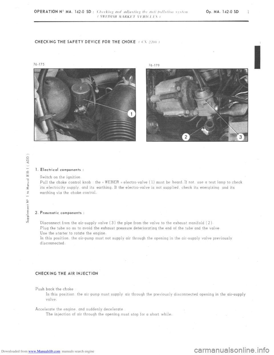
CHECKING THE SAFETY DEVICE FOR THE CHOKE i ( ?XO ,
2 1. Electrical components :
z
a Switch on the ignition
4 Pull the choke control knob the CC WEBER a) electto-valve ( 1) must be heard. If not use a test lamp to check
its electricity supply and its earthing. If the electro-valve is not supplied. check its energizinq and its
2
earthinq via the choke control.
5
;
E
; 2.P neurotic components :
?
“7
Disconnect from the air-supply valve ( 3 ) the pipe from the valve to the exhaust manifold ( 2 j
Plug the tube so as to avoid the exhaust pressure deteriorating the end of the tube and the valve
Use the starter to rotate the engine.
In this position the air-pump must not supply air through the opening in the air-supply valve previously
disconnecied.
CHECKING THE AIR INJECTION
Push bock the choke
In this position the air pump must supply air throuqh the previously disconnected opening in the air-supply
valve.
Accelerate the enqine. and suddenly decelerate
The injection of air through the openinq must stop for a short while.
Page 94 of 394
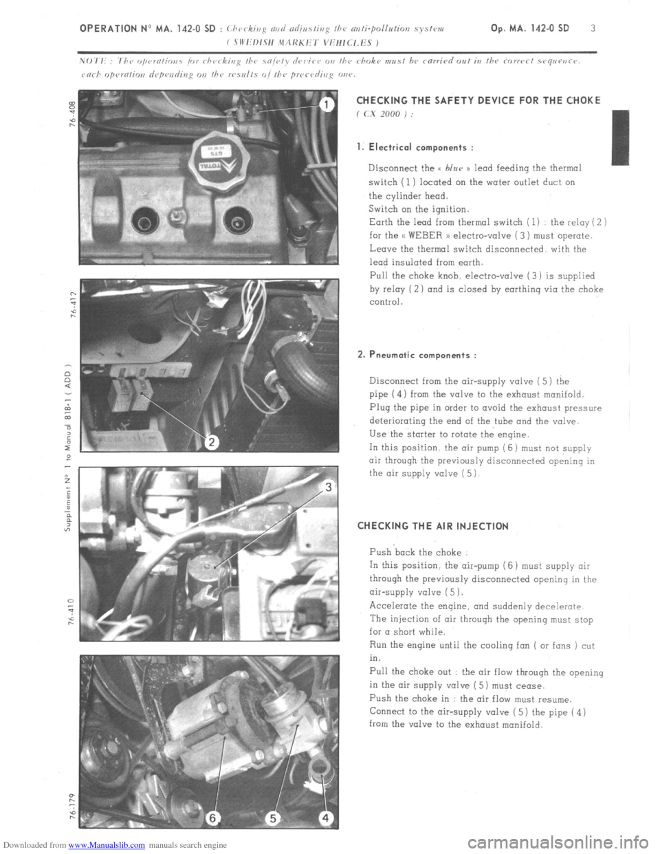
Downloaded from www.Manualslib.com manuals search engine CHECKING THE SAFETY DEVICE FOR THE CHOKE
f (.X 2000 j :
1. Electrical components :
Disconnect the u blur )) lead feeding the thermal
switch (1) located on the water outlet duct on
the cylinder head.
Switch on the ignition.
Earth the lead from thermal switch ( 1) the relay ( 2 )
for the << WEBER 1) electro-valve ( 3) must operate.
Leave the thermal switch disconnected with the
lead insulated from earth.
Pull the
choke knob. electro-valve (3) is supplied
by relay (2 ) and is closed by earthing via the choke
control.
2. Pneumatic components :
Disconnect from the air-supply valve ( 5) the
pipe (4) from the valve to the exhaust manifold.
Plug the pipe in order to avoid the exhaust pressure
deteriorating the end of the tube and the valve
Use the starter to rotate the engine.
In this position. the air pump (6 j must
not supply
air through the previously disconnected opening in
the air supply valve ( 5)
CHECKING THE AIR INJECTION
Push back the choke
In this position. the air-pump (6 ) must supply air
through the previously disconnected opening in the
air-supply valve ( 5 1.
Accelerate the engine, and suddenly decelerate
The injection of air throuqh the opening must stop
for a short while.
Run the engine until the cooling fan ( or fans ) cut
in.
Pull the choke out : the air flow through the opening
in the air supply valve ( 5) must cease.
Push the choke in : the air flow must resume.
Connect to the air-supply valve ( 5) the pipe ( 4 )
from the valve to the exhaust manifold.
Page 109 of 394
Downloaded from www.Manualslib.com manuals search engine COLD START INJECTOR
When the engine is cold, fuel settles on the inlet distribution chamber, and on the cylinder walls. Therefore, the
quantity of fuel which mixes with the inlet air is smaller than in an engine which has reached normal running
temperature. The mixture thus obtained will not ignite.
The cold-start injector enriches the mixture in each inlet duct by vaporizing fuel in the inlet manifold. However,
it only comes into operation when the starter motor is actuated, and when a thermal switch located inthe engine
coolanthas simultaneously closed the circuit.
‘A helicoidal spring compresses the mobile core of,the electro-magnet and its seal fuel cannot pass through.
When the magnetic core is attracted, the injector seat is freed-off, the fuel flows past the core. and.reached the
spiral effect injector, which injects the fuel, simultaneously giving it a spiral motion, and vaporizing it very finely. ‘THERMAL SWITCH
The thermal switch cuts out the operation of the cold-start injector when the temperature of the engine reaches
ir 35” C,,For any temperature below t 35’ C, the thermal switch limits the duration of injection. The maximum
duration is approximately 7.5 sets. at - 20’ C. Duration of injection is reduced as temperature increases
The variation in duration, determined by the thermal switch,.is obtained by means of a bi-metallic strip heated
by an electrical resistance. The bi-metallic strip cuts out the circuit according to the temperature reached after
it has heated for a certain amount of time.
Page 113 of 394
Downloaded from www.Manualslib.com manuals search engine ELECTRIC PETROL PUMP
The petrol pump is of the multi roller-vane type, driven by an electric motor which is energized as long as the
ignition is switched on. The rotor, which is fitted eccentrically in the pump housing, has metal roller vanes in
grooves around t.he periphery which, when they are forced outwards under the action of the centrifugal force, ensure
the system-is sealed.
Fuel is drawn into the cavities which,appear in between the roller-vanes, and is then forced into the injection
piping.
The electric motor is submerged’ in fuel. However, there .is no fire risk, since there is never any combustible
mixture in the pump housing. The pump supplies more fuel than the engine consumes under full load, so that
there is always sufficient pressure in the fuel system, whatever the engine speed. Excess fuel flows back to
the tank.
Once the ignition is on, the pump operates at the same time as the starter motor. Once the engine is running, the
airflow sensor energizes the pump.
Thanks to this type of.system, if an injector is faulty ( leaks ) the cylinder in question cannot be flooded if one
has ommitted to switch the ignition off. PETROL FILTER (1) :
A fuel filter, fitted between the pump and the injectors, prevents any impurities from reaching the injectors. PETROL PRESSURE REGULATOR ( 2 ) :
The fuel pressure is maintained constant by the pressure regulator. It comprises a metal housing
is a diaphragm., One side of the dipphragm.is subjected to the fuel under pressure, and the other 2
to the action of a calibrated spring. inside which
side is subjected
When the fuel pressure is in excess of 2 bars ( 29 psi ), the diaphragm lifts and allows fuel to flow back to the
tank.
The pressure provided by the regulator is pre-adjusted at the factory. The chamber on the side of the spring is
connected via a flexible pipe to the inlet manifold. Therefore, the difference between the pressure in the inlet
manifold and that of the fuel is maintained constant.
For any engine load, the drop in pressure at the injectors is therefore the same.
Page 131 of 394
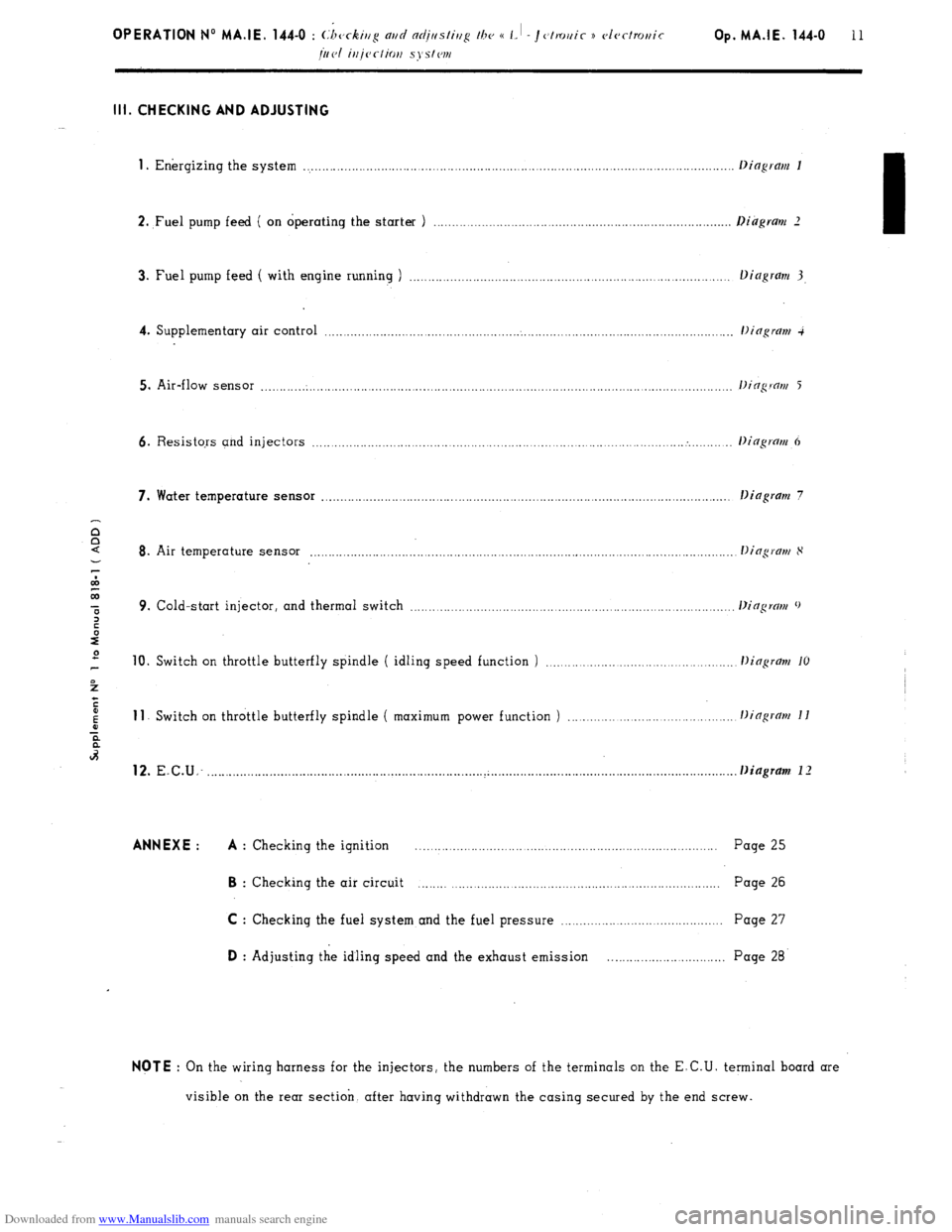
Downloaded from www.Manualslib.com manuals search engine Ill. CHECKING AND ADJUSTING
1
. Energizing the system ..................................................................................................................
2. ,Fuel pump feed ( on operating the starter ) .............................................................................
3. Fuel pump feed ( with engine running ) ...................................................................................
4. Supplementary air control ...........................................................................................................
5. Air-flow sensor ............................................................................................................................
6. Resistors and injectors ................................................................................................... . ........
7. Water temperature sensor ............................................................................................................ .
Dingram 7
8. Air temperature sensor ...............................................................................................................
9. Cold-start injector, and thermal switch ...................................................................................
10. Switch on throttle butterfly spindle ( idling speed function ) ............................................ 11
Switch on throttle butterfly spindle ( maximum power function ) ...................................... 12.
E.C.U: ......................................................................... ..~ ............................................................... . . Diagram 1 I ANNEXE : A
: Checking the ignition .................................................................................. Page 25 B
: Checking the air circuit ................................................................................ Page 26
C : Checking the fuel system and the fuel pressure ........................................... Page 27 D
: Adjusting the idling speed and the exhaust emission .............................. Page 28 NOTE
: On the wiring harness for the injectors, the numbers of the terminals on the E.C.U. terminal board are
visible on the rear section. after having withdrawn the casing secured by the end screw.
Page 132 of 394
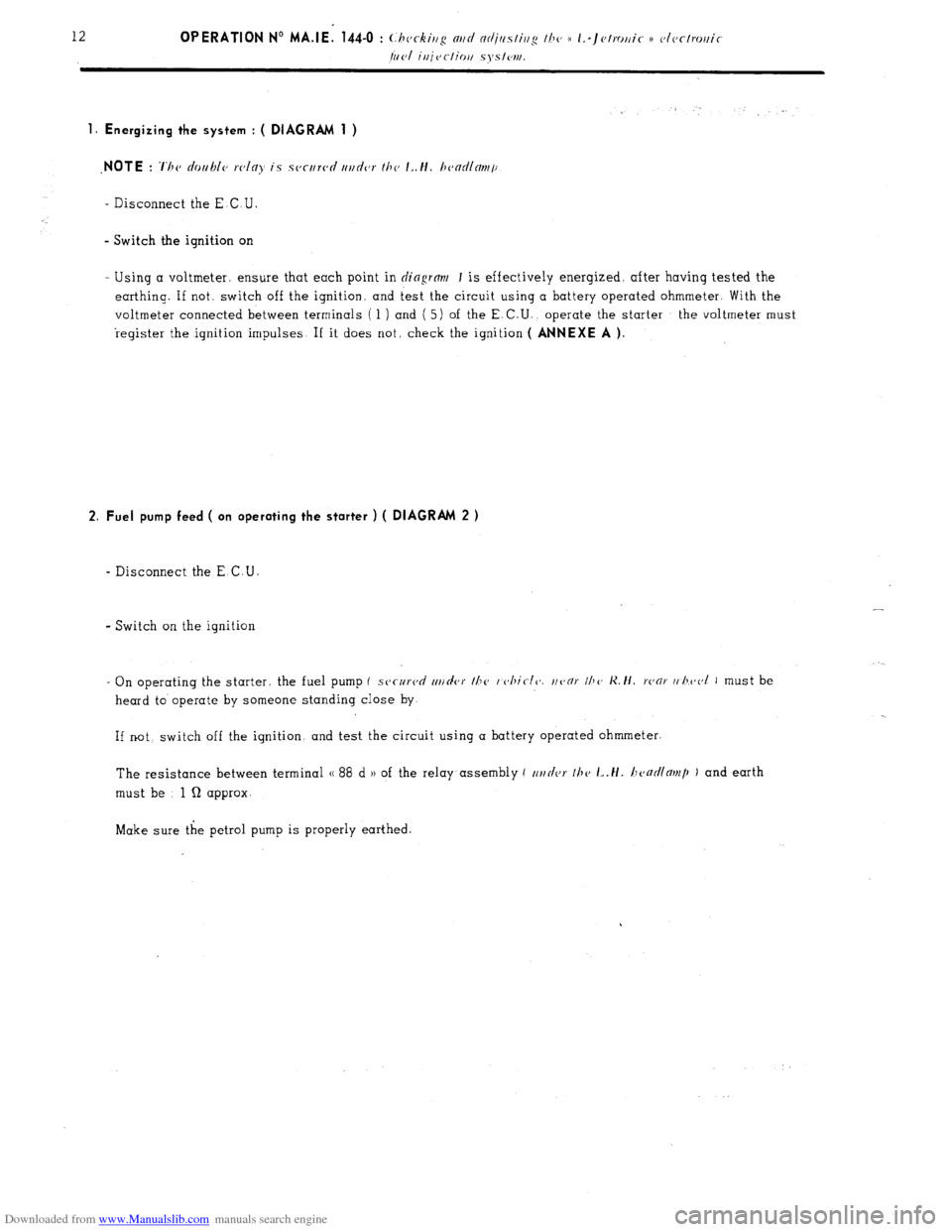
Downloaded from www.Manualslib.com manuals search engine 1. Energizing the system : ( DIAGRAM 1 )
_ Disconnect the E.C U
- Switch the ignition on
Using a voltmeter. ensure that each point in
dingrm 1 is effectively energised. after having tested the
earthing. If not, switch off the ignition. and test the circuit using a battery operated ohmmeter. With the
voltmeter connected between terminals ( 1 ) and ( 5) of the E. C.U., operate the starter the voltmeter must
register the ignition impulses If it does not. check the ignition
( ANNEXE A ).
2. Fuel pump feed ( on operating the starter ) ( DIAGRAM 2 )
- Disconnect the E C.U.
- Switch on the ignition
- On operating the starter. the fuel pump (
secureri rrt/rler the I c~hiclc’. uoor IIJO K. ti. ronr (, l~eol I must be
heard to operate by someone standing close by
If not switch off the ignition, and test the circuit using a battery operated ohmmeter.
The resistance between terminal (( 88 d H of the relay assembly ( c~r~tler 111~
L,H. honr/llor)~p ) and earth
must be 1 Q approx-
Make sure the petrol pump is properly earthed.