Front CITROEN CX 1988 Service Manual
[x] Cancel search | Manufacturer: CITROEN, Model Year: 1988, Model line: CX, Model: CITROEN CX 1988Pages: 648, PDF Size: 95.8 MB
Page 2 of 648
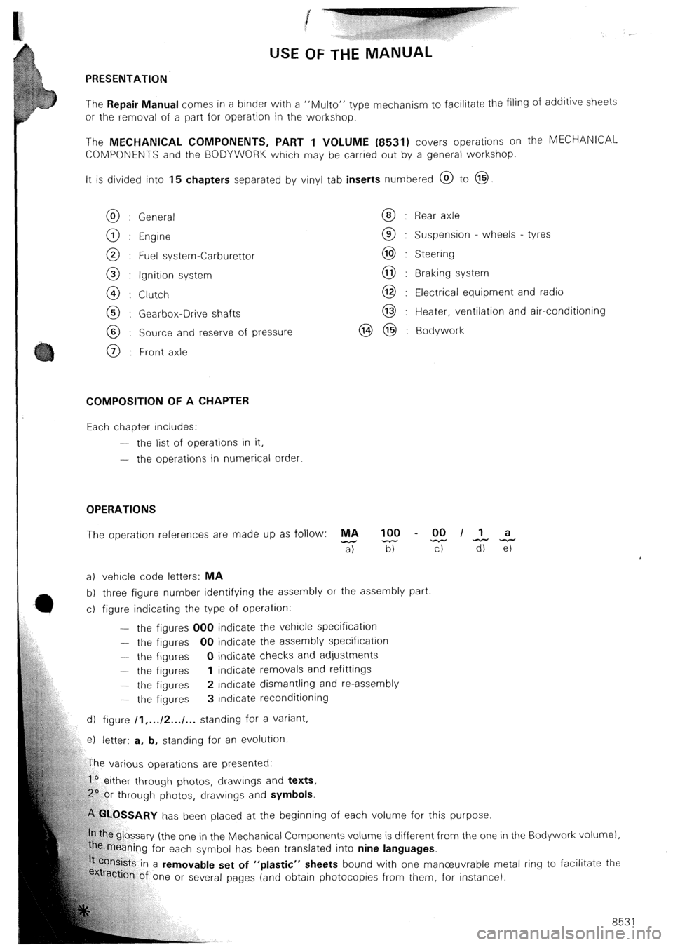
USE OF THE MANUAL
PRESENTATION
The Repair Manual comes in a binder with a “Mu/to” type
mechanism to facilitate the filing of additive sheets
or the removal of a part for operation in the workshop.
The MECHANICAL COMPONENTS, PART 1 VOLUME (8531) covers operations on the MECHANlCAL
COMPONENTS and the BODYWORK which may be carried out by a general workshop.
It is divided into 15 chapters separated by vinyl tab inserts numbered @ to @
General
Engine
Fuel system-Carburettor
Ignition system
Clutch
Gearbox-Drive shafts
Source and reserve of pressure
Front axle Rear axle
Suspension - wheels - tyres
Steering
Braking system
Electrical equipment and radio
Heater, ventilation and air-conditioning
Bodywork
COMPOSITION OF A CHAPTER
Each chapter includes:
-
the list of operations in it,
-
the operations in numerical order.
OPERATIONS
The operation references are made up as follow: MA 100 - 00 II a
-
a) z T-r TiiTz
a) vehicle code letters: MA
b) three figure number identifying the assembly or the assembly part
c) figure indicating the type of operation:
-
the figures 000 indicate the vehicle specification
- the figures 00 indicate the assembly specification
- the figures 0 indicate checks and adjustments
- the figures 1 indicate removals and refittings
- the figures 2 indicate dismantling and re-assembly
-
the figures 3 indicate reconditioning
d) figure /I,... /2.../... standing for a variant,
e) letter: a, b, standing for an evolution
rious operations are presented:
1’ either through photos, drawings and texts,
hrough photos, drawings and symbols.
‘!%.OSSARY has been placed at the beginning of each volume for this purpose.
e glossary (the one in the Mechanical Components volume is different from the one in
caning for each symbol has been translated into nine languages.
kts in a removable set of “plastic” sheets bound with one manceuvrable me
ion of one or several pages (and obtain photocopies from them, for instance). the Bodywork volur nel,
‘tal r ing to facilitate the
85 31
Page 35 of 648

11
0 D Vorderachse : Unterer Querlenker
0 OK Forbro : Nederste baerearm
0 E Eje delantero : Brazo inf6rior
0 GB Front axle : Lower arm
0 1 Assale anteriore : Braccio inferiore
0 Nl. Voorbrug : Onderdraagarm
0 P Eixo dianteiro : BraGo inferior
0 S Framvagn : Undre I;inkarm
0 F Essieu avant : Bras infbrieur
0 D Vorderachse : Achsschenkel
0 DK Forbo : Styreboit
0 E Eje delantero : Pivote
0 GB Front axle : Swivel assembly
0 1 Assale anteriore : Pivot
0 NL Voorbrug : Fusee
0 P Eixo dianteiro : Pivot
0 S Framvagn : Pivot
0 F Essieu avant : Pivot
0 D Klasse 0 NL Klasse
0 DK Klasse 0 P Classe
0 E Clase 0 S Klass
0 GB Class
0 I Classe 0 F Classe
0 D Ablassen
0 DK T$mme
0 E Vaciar
0 GB Drain
0 1 Svuotare
0 D Entliiften
0 DK Udlufte
0 E Purgar
0 GB Bteed
0 I Spurgare
0 NL Ontluchten
0 P Purgar
0 s Lufta
0 F Purger
0 D Bearbeiten
0 DK Bearbejde
0 E Mecanizar
0 GB Machine
0 1 Lavorare
0 NL Bewerken
0 P Trabalhar a maquina
0 S Bearbeta, slipa. etc.
0 F Usiner
Page 91 of 648

REMOVING AND REFITTING
THE ENGINE/GEARBOX ASSEMBLY
- 2.5 LITRE CX WITH PETROL INJECTION -
REMOVAL
Support the car on stands horizontally, Fig. I using
the three stands 6602-T, in order to facilitate the
removal of the power unit assembly and to reposition
it more easily on the stands.
Depressurize the hydraulic system.
Drain the brake accumulator.
Set the height control to the “low” position
Remove:
- the battery,
- the bonnet,
- the front wheel,
- the spare wheel
- the protection plate located under the spare wheel,
Drain the cooling circuit via the drain hose of the
radiator.
Take off the crankcase drain plug (I 1, Fig. II.
Remove the drive-shafts:
(Refer to Op @ MA.372. l/l)
Uncouple: hoses (6) and (71, Fig. IV (protecting the
alternator from water entry at “a”).
Disconnect the engine cooling fan thermal switch.
Remove the engine heat sink.
Extract, Fig. Ill:
- the screws that secure horn (2) support, passing
through the wheelarch,
- the wheelarch lining. Disconnect:
- wiring harnesses (3) from the battery positive lead,
Fig. Ill,
- the ground cable from the gearbox,
- the wiring harness from the reversing lamp switch.
Remove, Fig. Ill:
- the pressure regulator accumulator,
- pipe (4) between pressure regulator and brake accu-
mulator.
Vehicle with air conditioning option:
- the belt protective cover,
- the air conditioning compressor drive belt
Uncouple:
- the air intake casing position accelerator cable,
- the high pressure pump rubber suction pipe,
- the high pressure pump outlet pipe (5) and its attach-
ment, Fig. Ill.
Disconnect: Fig. V
- the throttle spindle switch (IO),
- knock sensor (14).
Uncouple: Fig. V
- pressure sensor pipe(91,
- supplementary air pipe (I I),
- cylinderhead cover pipe (I 21,
- breather pipe (8).
Remove suction pipe (I 3) situated between the flow-
meter and the turbocharger or between the flowme-
ter and the inlet manifold.
Page 97 of 648

le up the exhaust system. econnect, Fig. IV and V:
- connectors 11 I),
turaily aspirated engines w/th EN, fitted with
seals:
Tighten the flange to 1.6 mda
On the turbocharged engines with EH, fitted with
NEW nuts and seals:
Refit: Fig. I and II, - sensor (12) (with biue /dent mark),
- sensor (13) (with no ident mark),
- HT coil 191 cyls 1 and 4 (with yellow /dent mark),
HT coil i IO) cyls 2 and 3 (w/t/r fro markl,
- the suppressors,
- the reversing larnp switch wrring harness,
- the throttle spindle switch (141,
- knock sensor (I 8).
- flexible pipe (2) to the pressure release valve outlet,
- exhaust pipe (4) to the turbo, screws (31, distance
pieces (51,
- screw (6) and adjusting shims.
There should be a 5 mm clearance at least between
the exhaust pipe and the engine crankcase. Recouple, Fig. V and VI:
- the water hoses,
- air circurt pipes (151, (161, (17). (20) and (211,
- petrol circuit pipes (I 9),
- gear shift link rods,
- the accelerator cable.
Tighten, Fig. I and II:
- turbocharger nuts fin the correct sequence), Fig. II,
- flexible hose (2) screws (3) and nuts (I 1 to
2.5 mdaN,
- screw (6) to 5 mdaN. Fit:
- the driveshafts,
(See Op. @ MA 372-l/11
- the radiator,
- the bonnet,
- the battery,
Refit: Fig. Ill
- the pressure regulator and compressor holder (air
conditioning option) together with its shims; tigh-
ten nuts (7) to 5 mdaN. - the protection plate located under the spare
wheel.
Check the oil levels. Top up if necessary.
Vehicles with air-conditioning: Fill up the cooling circuit (wrth the heater open) and
carry out the bleeding operation.
- the compressor belt and protection cover,
- the pressure regulator accumulator, fitted with a
NEW seal,
- the HP pump outlet pope, fitted with a NEW sea/
and its fastenings (8),
- the pipe situated between the pressure regulator
and the brake accumulator, fitted with NEWseals,
- the HP pump rubber suction pipe,
- the horn. (As per Op @ MA 230.0/l/.
Bleed the front brakes.
(Refer to Op. MA 453.0/l/.
Check the gear change.
Lower the vehicle to the ground.
Page 102 of 648
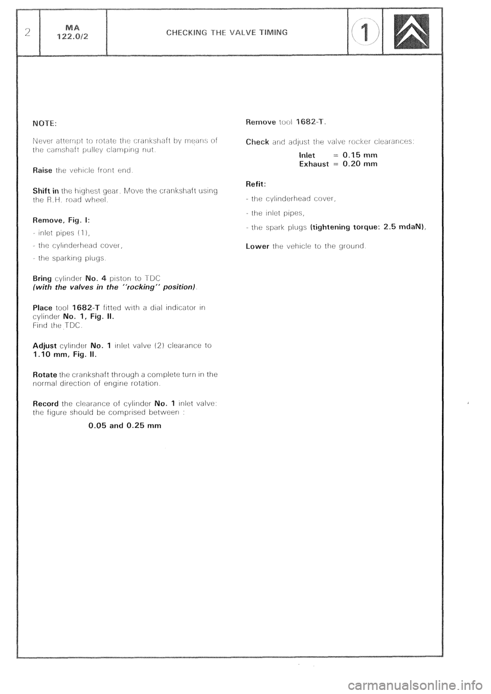
Raise ihe vei-~cle front end
Shift in the i-\~yi-\est gear. Move the crankshaft using
t!le R.H. road wheel.
Remove, Fig. I:
- inlet pipes (I 1,
- tilt: cyllnderlleati CoveI,
- the sparkIng plugs
o. 4 piston to TDC
(with the valves in the “rocking” position).
Place tool 1682-T fitted with a dial indicator In
cylinder No. 1, Fig. II.
Firlti ihe TDC.
Adjust cylinder No. 1 lrllel valve (2) clearance to
1.10 mm, Fig. II.
Rotate the cl-ankshaft through a complete turn In the
normal direction of engine rotation.
Record the clearance of cylirlder No. 1 inlet valve:
the figure should be comprised between :
0.05 and 0.25 mm eck and adlust ihe valve locker clearances.
Inlet = 0.15 mm
Exhaust = 0.20 mm
Refit:
- the cylinderhead cover,
the inlet pipes,
- the spark plugs (tightening torque: 2.5 mdaN),
Lower the vehicle to the ground
Page 113 of 648
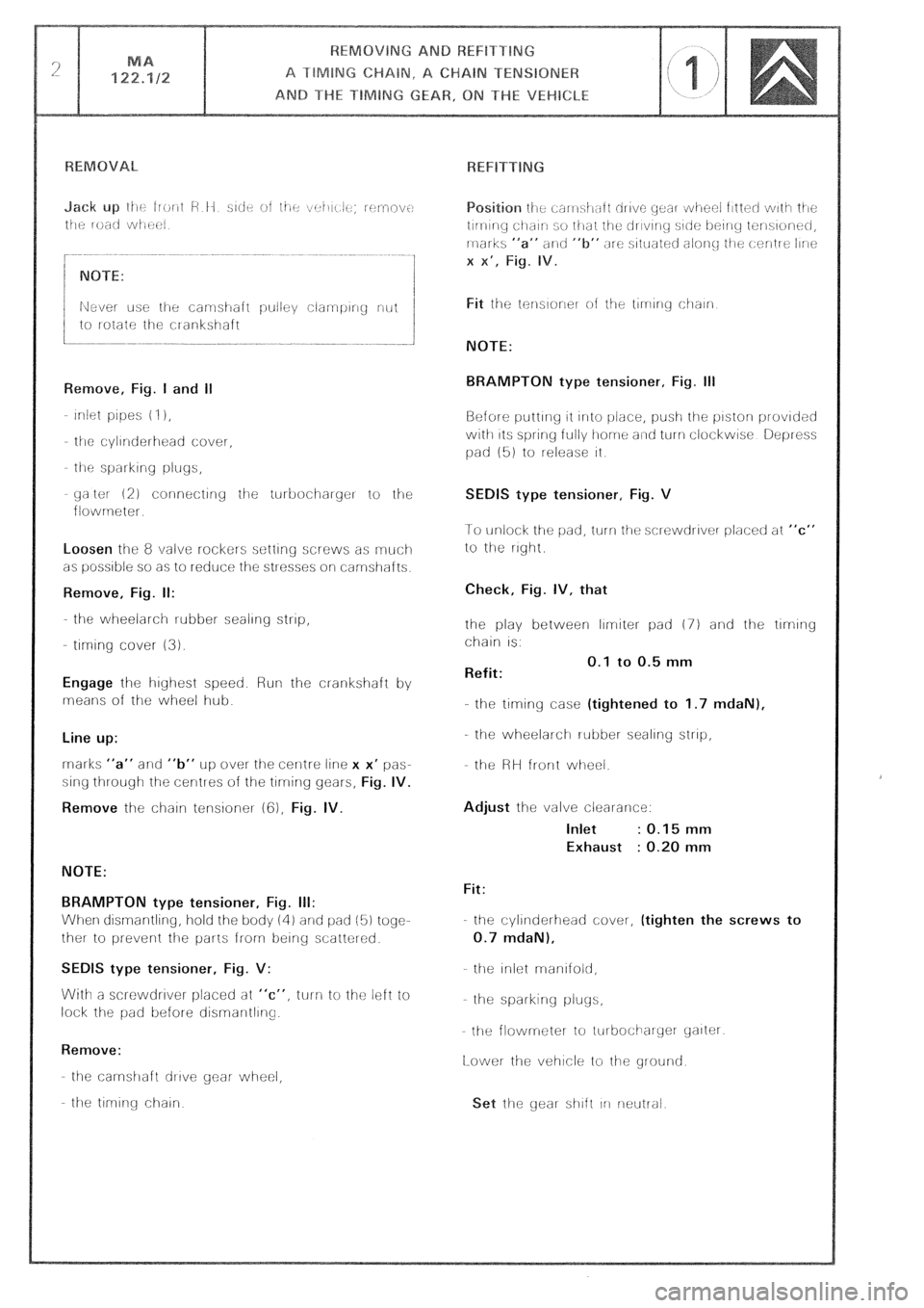
yaltot 12) connectiriy iije turbocihaiger to the
flowrneter.
Loosen the 8 valve rockers setting screws as rnuci-1
as possible so as to reduce the stresses oli camshafts
Remove, Fig. II:
the wheelarch rubber sealing strip,
- tlrmng cover (3).
Engage lhe highest speed. Run the cl-ankshaft by
means of the wheel hub.
Line up:
rnarks “a” and “b” UP over the cenlre line x x’ pas-
sing through the centres of the tlrrring gears,
Fig. IV.
Remove
the chain tensioner (cj), Fig. IV.
NOTE:
BRAMPTON type tensioner, Fig. III:
When dismantling, hold the body iii) and pad (5) togc-
ther to prevent the parts from being scatter&
SEDlS type tensioner, Fig. V:
With a screwdrlver placed at “c”, turn to the left io
lock the pad before disrnarltllrlg.
Remove:
the carnshaft drive gear- wheel,
the tlrnlr-ig chain
NOTE:
BRAMPTON type tensioner, Fig. Ill
Before putting 11 irrlo i.)ir!ce, push the pistorl provided
with 11s spring fully home a~rtl turn clockwise Depress
pad (51 to release it
SEDIS type tensioner, Fig. V
1-o unlock the pad, turn tile sclewdrlver placed at “c”
to the right
Check, Fig. IV, that
the play between limiter pad (7) and the tlmng
chain IS.
Refit: 0.1 to 0.5 mm
-.
the timing case (tightened to 1.7 mdaN),
the wheelarch rubber sealing strip,
the HH front wheel.
Adjust the valve clearance:
Inlet : 0.15 mm
Exhaust : 0.20 mm
Fit:
the cylinderhead cover, (tighten the screws to
0.7 mdaN),
the Iniot rnanlfold,
he spai-king pluys,
the flowmeter to iurbocilarycr yalter
[Lower the vehicle to the ground
Page 132 of 648
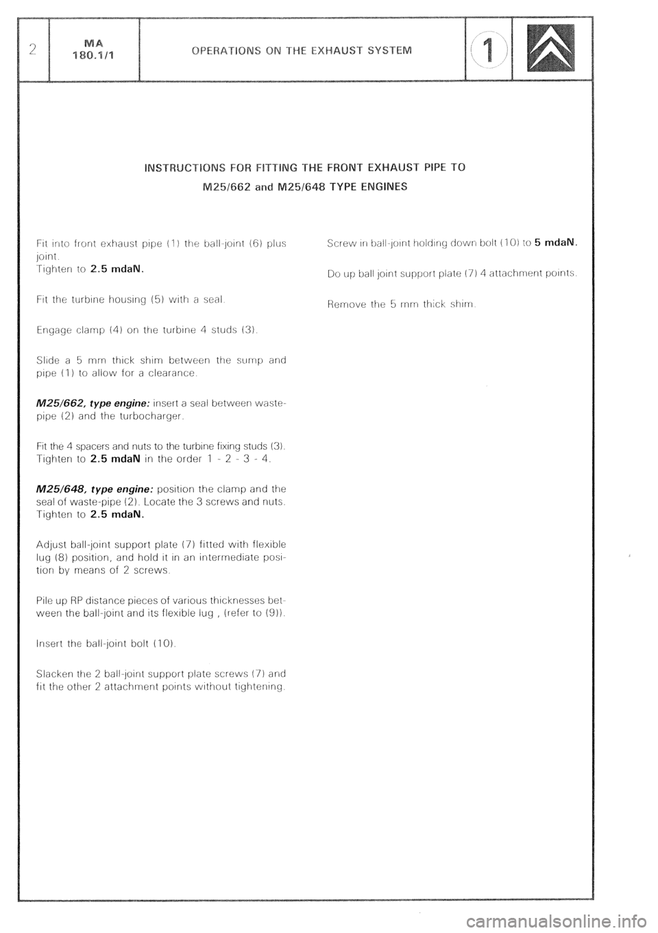
ht into front exhaust pope (I ) the ball~joint (6) plus
joint
Tighter to 2.5 mdaN.
Ftt the turbine housing (51 vuith a seal
Engage clamp 141 oli the turbine 4 studs (3)
Slide a 5 rnn- thick shim between the sump and
pipe (I ) to allow for a clearance
M25/662, type engine: insert a seal between waste-
pipe 12) and the turbocharger.
Fit the 4 spacers and nuts to the turbine fixing studs (3).
Tighter to 2.5 mdaN in the order 1 - 2 - 3 - 4.
M25/648, type engine: position the clamp and the
seal of waste-pipe (2). Locate the 3 screws and nuts.
Tighten to 2.5 mdaN.
Adjust ball-jotnt support plate 17) fitted with flexible
lug (8) position, and hold It In an intermediate
pow
tion by means of 2 screws
Pile up RP distance pieces of various thicknesses bet-
ween the ball-joint and its flexible lug , ilefer to 1911.
Insert the ball-joint bolt (1 0).
Slacker ttre 2 ball-joint support plate screws (7) and
fit the other 2 attachment points without tightening Screw 111 ball-Joirnt t~old~ny down bolt (I 0) to 5 mdaN.
Do up ball Joint support plate (7) 4 attachment points
Page 286 of 648
FRONT MA
412.1/l 1
RECOMMENDED TOOLS
6303-T.
Upper arm shaft extractor. 6320-T.
Anti-roll bar link rod extractor 6602-T.
Set of three stands.
REMOVING AND REFITTING
AN UPPER WHEEL ARM
8531-8532
Page 287 of 648
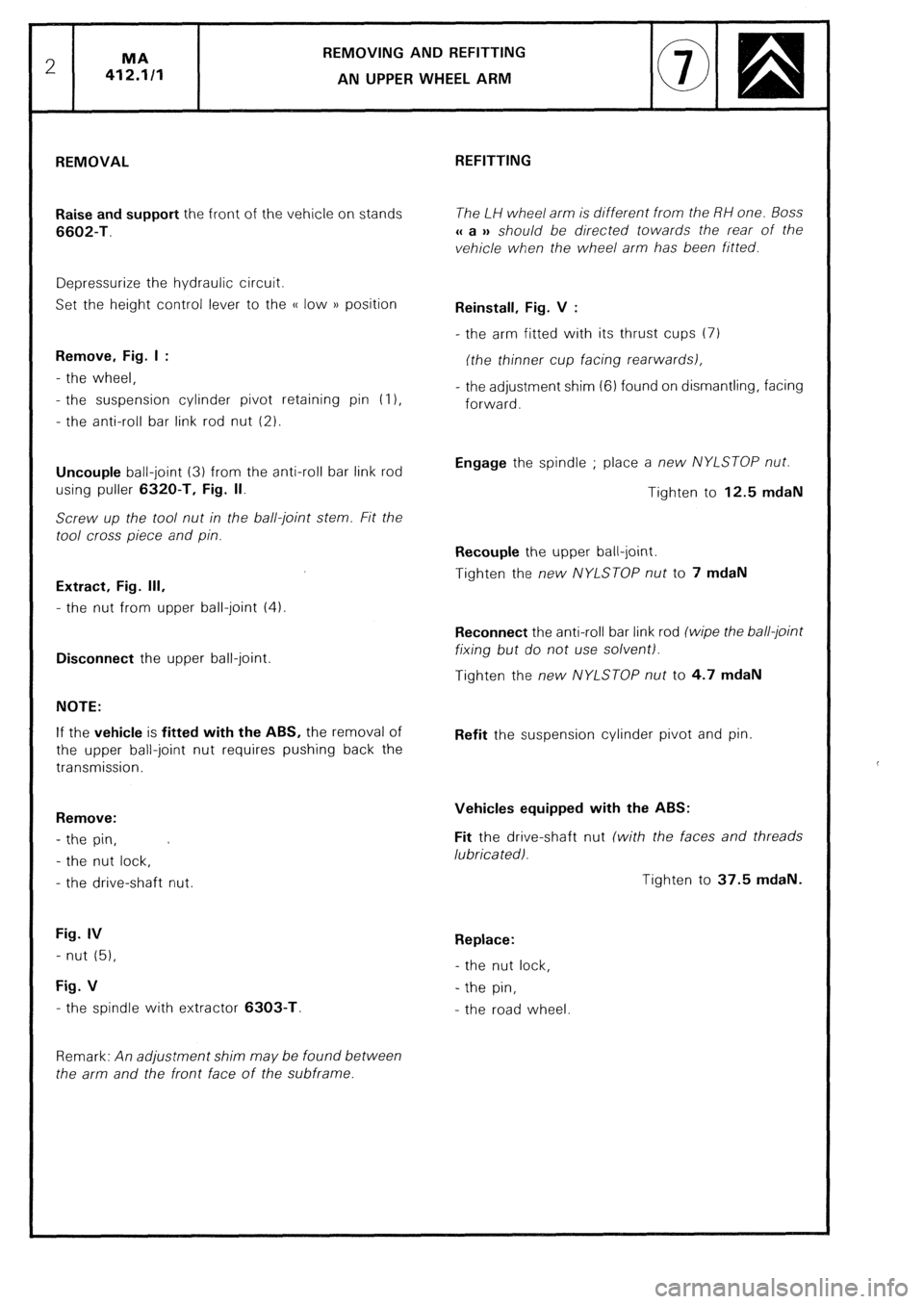
REMOVING AND REFITTING
AN UPPER WHEEL ARM
REMOVAL
Raise and support the front of the vehicle on stands
6602-T.
Depressurize the hydraulic circuit.
Set the height control lever to the (( low )) position
Remove, Fig. I :
- the wheel,
- the suspension cylinder pivot retaining pin (I 1,
- the anti-roll bar link rod nut (2).
Uncouple ball-joint (3) from the anti-roll bar link rod
using puller 6320-T. Fig. II.
Screw up the tool nut in the ball-joint stem. Fit the
tool cross piece and pin.
Extract, Fig. Ill,
- the nut from upper ball-joint (4).
Disconnect the upper ball-joint.
NOTE:
If the vehicle is fitted with the ABS, the removal of
the upper ball-joint nut requires pushing back the
transmission.
Remove:
- the pin, C
- the nut lock,
- the drive-shaft nut.
Fig. IV
- nut (51,
Fig. V
- the spindle with extractor 6303-T.
Remark: An adjustment shim may be found between
the arm and the front face of the subframe. REFITTING
The LH wheel arm is different from the RH one. Boss
u a )a should be directed towards the rear of the
vehicle when the wheel arm has been fitted.
Reinstall, Fig. V :
- the arm fitted with its thrust cups (7)
frhe thinner cup facing rearwardsl,
- the adjustment shim (6) found on dismantling, facing
forward.
Engage the spindle ; place a new NYLSTOP nut.
Tighten to 12.5 mdaN
Recouple the upper ball-joint.
Tighten the new NYLSTOP nut to 7 mdaN
Reconnect the anti-roll bar link rod (wipe the ball-joint
fixing but do nor use solventl.
Tighten the new NYLSTOP nut to 4.7 mdaN
Refit the suspension cylinder pivot and pin.
Vehicles equipped with the ABS:
Fit the drive-shaft nut (with the faces and threads
lubricated).
Tighten to 37.5 mdaN.
Replace:
- the nut lock,
- the pin,
- the road wheel
Page 290 of 648
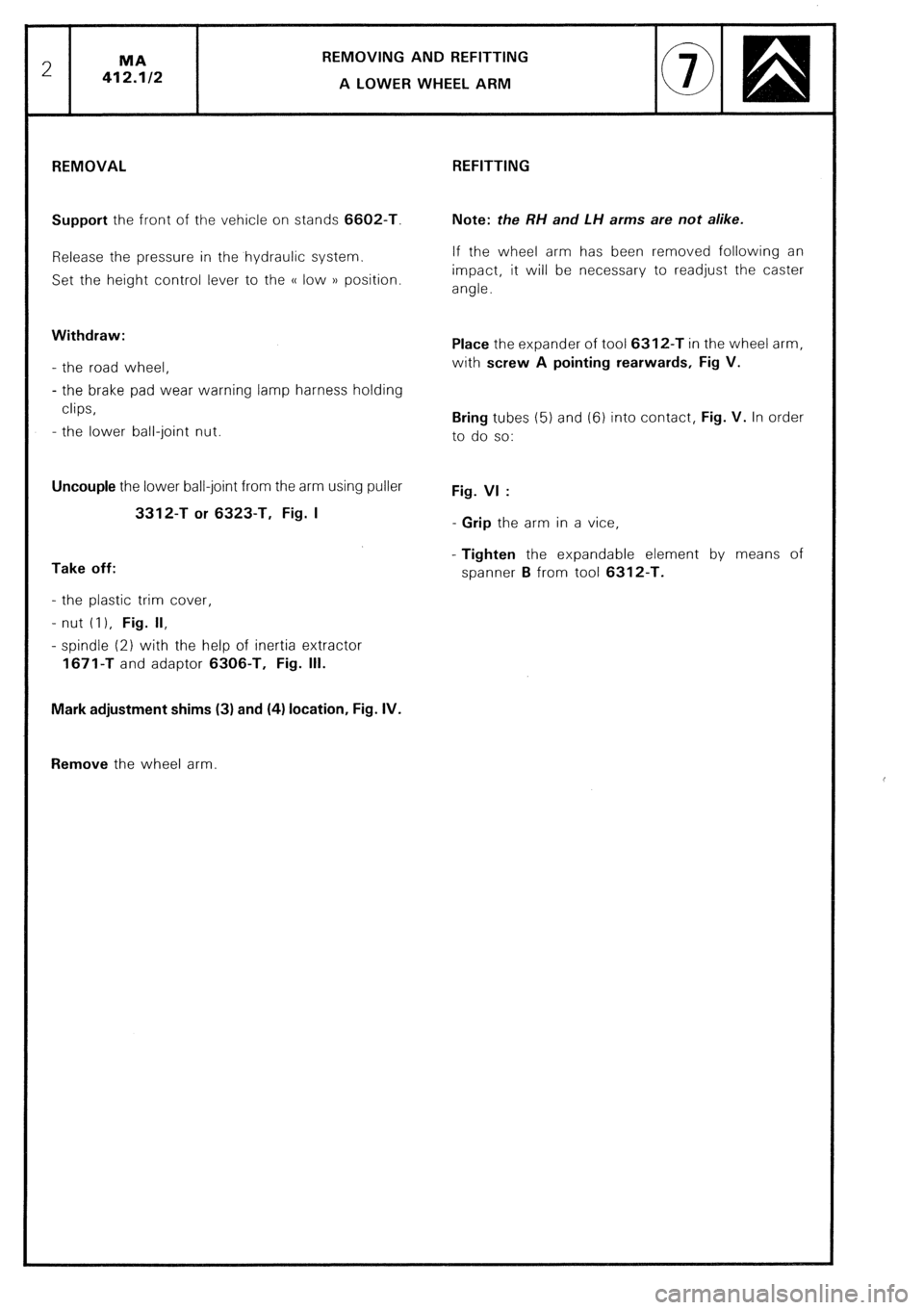
REMOVING AND REFITTING
REMOVAL
Support the front of the vehicle on stands 6602-T.
Release the pressure in the hydraulic system.
Set the height control lever to the (( low )) position.
Withdraw:
- the road wheel,
- the brake pad wear warning lamp harness holding
clips,
- the lower ball-joint nut.
Uncouple the lower ball-joint from the arm using puller
3312-T or 6323-T, Fig. I
Take off:
- the plastic trim cover,
- nut (I 1, Fig. II,
- spindle (2) with the help of inertia extractor
1671-T and adaptor 6306-T, Fig. Ill.
Mark adjustment shims (3) and (4) location, Fig. IV.
Remove the wheel arm. REFITTING
Note: the RH and LH arms are not alike.
If the wheel arm has been removed following an
impact, it will be necessary to readjust the caster
angle.
Place the expander of tool 6312-T in the wheel arm,
with screw A pointing rearwards, Fig V.
Bring tubes (5) and (6) into contact, Fig. V. In order
to do so:
Fig. VI :
- Grip the arm in a vice,
- Tighten the expandable element by means of
spanner B from tool 6312-T.