battery CITROEN CX 1988 Service Manual
[x] Cancel search | Manufacturer: CITROEN, Model Year: 1988, Model line: CX, Model: CITROEN CX 1988Pages: 648, PDF Size: 95.8 MB
Page 17 of 648
PROTECTION OF THE ELECTRICAL COMPONENTS
PRECAUTIONS TO BE TAKEN WHEN CARRYING OUT AN OPERATION ON THE VEHICLE
It is essential to avoid actrons which may damage the electrical or the electronic equipment or create a short circuit
(wrth subsequent risk of fire or accident).
Battery:
a) First disconnect cable clamp from the battery negative terminal, earthed, then from the positive post.
b 1 Before tightening the negative clamp to the battery (the negative lead should be connected last), ensure that there
is no short circuit (bright sparks or arcs).
Small sparks may occur due to the interior lamp (door open), door locking device, clock or components having
remained in operation.
c 1 Make sure that the terminals are properly connected. Clamps and terminals should be clean and correctly tightened.
d ) When recharging the battery, disconnect the two clamps first.
e) Do not reverse the negative and positive clamps on the battery. (This could destroy the alternator diodes).
Fuses:
a 1 Fit the correct type of fuses: use the fuses specified for the protected devices
b 1 Take the added accessories and the functions into consideration.
Charging circuit:
,a 1 Do not run the alternator unless it is connected to the battery. Do not disconnect the battery when the alternator
is rotating.
b 1 Ensure that the regulator is correctly earthed.
c ) Do not interchange the leads connected to the regulator, (charge detection warning lamp and excitation are specific).
d ) Do not connect a suppressor capacitor to the regulator without taking precautions or following proper
instructions.
e 1 Do not use an electric welding equipment on the vehicle without having first disconnected the alternator, the regula-
tor and the battery (insulate the two terminals).
f 1 Do not R check )) the operation of an alternator by short circuiting the positive and ground terminals, which may
destroy the diodes.
Starting the engine:
Do not use a booster or a 24-volt battery. Only use a correctly charged 12-volt battery (a higher capacity battery may
be utilised). Otherwise, risk of deterioration of the ignition module or any other electronic control units. If the starter
is needed for starting the engine, without running it, it is necessary to disconnect datum and flywheel sensors on the
All Electronic Ignition, or the primary lead of the coil on any other type of ignition.
Ignition:
a 1 Do not connect a suppressor capacitor to the negative terminal of the coil.
b 1 Do not operate the module if its radiator is not connected to the earth.
c 1 Fit the radio suppressor capacitors recommended by the factory.
d 1 Never operate the ignition system while the HT circuit is open. Connect the HT leads to earth
e) Only use rev. counter having a HT sensor, (never puncture HT leads).
0.1. bulb:
a) Never replace a 01. bulb with the headlamp switched on. If the headlamps have been in use, allow them to cool down.
b) Do not touch a 0.1. bulb with bare fingers. Any fingerprints must be cleaned with soapy water and the bulb dried
with a dry lint-free cloth.
Checks :
a) Preferably use a high resistance (> 10 k Q VI voltmeter or a battery-operated ohm-meter
b) Take care not to use instruments taking their power from the mains.
Electronic components:
a) Avoid overvoltages due to a badly insulated charger, electric arcing or connections to the coil.
The units such as regulator, ignition module, tachometer, windscreen wiper timer, flasher unit, clock, radio, oil gauge
unit, door lock control unit, etc. comprising electronic components may be deteriorated.
b) The electronic components should not be placed or operated under a temperature exceeding 80°C.
c) Always switch off instruments or electronic control units before connecting or disconnecting them.
‘
Page 91 of 648

REMOVING AND REFITTING
THE ENGINE/GEARBOX ASSEMBLY
- 2.5 LITRE CX WITH PETROL INJECTION -
REMOVAL
Support the car on stands horizontally, Fig. I using
the three stands 6602-T, in order to facilitate the
removal of the power unit assembly and to reposition
it more easily on the stands.
Depressurize the hydraulic system.
Drain the brake accumulator.
Set the height control to the “low” position
Remove:
- the battery,
- the bonnet,
- the front wheel,
- the spare wheel
- the protection plate located under the spare wheel,
Drain the cooling circuit via the drain hose of the
radiator.
Take off the crankcase drain plug (I 1, Fig. II.
Remove the drive-shafts:
(Refer to Op @ MA.372. l/l)
Uncouple: hoses (6) and (71, Fig. IV (protecting the
alternator from water entry at “a”).
Disconnect the engine cooling fan thermal switch.
Remove the engine heat sink.
Extract, Fig. Ill:
- the screws that secure horn (2) support, passing
through the wheelarch,
- the wheelarch lining. Disconnect:
- wiring harnesses (3) from the battery positive lead,
Fig. Ill,
- the ground cable from the gearbox,
- the wiring harness from the reversing lamp switch.
Remove, Fig. Ill:
- the pressure regulator accumulator,
- pipe (4) between pressure regulator and brake accu-
mulator.
Vehicle with air conditioning option:
- the belt protective cover,
- the air conditioning compressor drive belt
Uncouple:
- the air intake casing position accelerator cable,
- the high pressure pump rubber suction pipe,
- the high pressure pump outlet pipe (5) and its attach-
ment, Fig. Ill.
Disconnect: Fig. V
- the throttle spindle switch (IO),
- knock sensor (14).
Uncouple: Fig. V
- pressure sensor pipe(91,
- supplementary air pipe (I I),
- cylinderhead cover pipe (I 21,
- breather pipe (8).
Remove suction pipe (I 3) situated between the flow-
meter and the turbocharger or between the flowme-
ter and the inlet manifold.
Page 94 of 648
- pressure regulator- and compressor holder nuts (1 )
(a//- condit/oning option).
- all the sfirms,
and put them rn place of the battery.
Uncouple the exhaust systern.
Normally aspirated engine with E. F. I..
Remove the 4 exhaust pipe nuts.
Turbo with E./Y/., Fig. II and 111
Remove:
- screw (2) and shims (31,
- flexrble pipe screws (7),
- nuts and spacers (4).
Release exhaust pipe (8) downwards.
Remove nuts (5) and flexible pipe (6). - adtustrng nuts (91,
- clutch control support screws (I 0).
Uncouple the power take off with double outlet,
Fig. V.
Fully loosen screw i 121, then retrghten it by two turns
to prevent the speedometer drive guide from being
pushed out.
Disengage the twin outlet power take off ( 1 1).
Remove oil gauge i 13).
Uncouple, Fig. V:
- heater hoses (I 6) and (I 71,
- fast idle air duct (I 5),
- petrol supply pipe (181,
- petrol return pipe (14).
Disconnect, Fig. VII:
- connectors (201,
- sensors (221,
- coils and suppressors (I 9),
- gear shift link rods (21 ).
Page 97 of 648

le up the exhaust system. econnect, Fig. IV and V:
- connectors 11 I),
turaily aspirated engines w/th EN, fitted with
seals:
Tighten the flange to 1.6 mda
On the turbocharged engines with EH, fitted with
NEW nuts and seals:
Refit: Fig. I and II, - sensor (12) (with biue /dent mark),
- sensor (13) (with no ident mark),
- HT coil 191 cyls 1 and 4 (with yellow /dent mark),
HT coil i IO) cyls 2 and 3 (w/t/r fro markl,
- the suppressors,
- the reversing larnp switch wrring harness,
- the throttle spindle switch (141,
- knock sensor (I 8).
- flexible pipe (2) to the pressure release valve outlet,
- exhaust pipe (4) to the turbo, screws (31, distance
pieces (51,
- screw (6) and adjusting shims.
There should be a 5 mm clearance at least between
the exhaust pipe and the engine crankcase. Recouple, Fig. V and VI:
- the water hoses,
- air circurt pipes (151, (161, (17). (20) and (211,
- petrol circuit pipes (I 9),
- gear shift link rods,
- the accelerator cable.
Tighten, Fig. I and II:
- turbocharger nuts fin the correct sequence), Fig. II,
- flexible hose (2) screws (3) and nuts (I 1 to
2.5 mdaN,
- screw (6) to 5 mdaN. Fit:
- the driveshafts,
(See Op. @ MA 372-l/11
- the radiator,
- the bonnet,
- the battery,
Refit: Fig. Ill
- the pressure regulator and compressor holder (air
conditioning option) together with its shims; tigh-
ten nuts (7) to 5 mdaN. - the protection plate located under the spare
wheel.
Check the oil levels. Top up if necessary.
Vehicles with air-conditioning: Fill up the cooling circuit (wrth the heater open) and
carry out the bleeding operation.
- the compressor belt and protection cover,
- the pressure regulator accumulator, fitted with a
NEW seal,
- the HP pump outlet pope, fitted with a NEW sea/
and its fastenings (8),
- the pipe situated between the pressure regulator
and the brake accumulator, fitted with NEWseals,
- the HP pump rubber suction pipe,
- the horn. (As per Op @ MA 230.0/l/.
Bleed the front brakes.
(Refer to Op. MA 453.0/l/.
Check the gear change.
Lower the vehicle to the ground.
Page 105 of 648
- the road wheel,
- the wheelarch lining,
the belt protection covers,
- the engine oil filler plug.
Position:
- the valves of cylinder No. 1 in the “rocking” postion
(look Into the oil filler neck),
- the flywlleel, with marks + + aligned, Fig. I. t/hat mark 1s opposite screw 121,
- ttlat the:ie ar-e 35 pitches between marks and
passing al-ounc tensioner roller- (I 1.
Refit:
- the filler plug,
- the timing belt covers,
- the wheelarch lining,
- the wheel
Reconnect the battery negative cable
Page 212 of 648
CHECKING AND ADJUSTING
THE INJECTION SYSTEM
II. - INSPECTION AND TIMING OF THE “ROT0-DIESEL” INJECTION PUMP
Raise the LH side of the vehicle and support it on
stands.
Disconnect the battery negative lead.
Engage the 5th gear. Rotate the engine by turning the
wheel.
Set the No. 1 cylinder to the initial timing point,
Fig.1.
(look into the oil filter orifice).
- place cylinder No. 1 valves in the rocking position;
turn the crankshaft by one turn in the normal direc-
tion of engine rotation.
- align marks on the flywheel and on the crankcase
(++I.
- turn the crankshaft back through a quarter of a turn.
Remove either the plug (with a 32 mm ring spanner)
or the inspection plate depending on the type of the
pump.
Refit, Fig II or Ill, according to pump:
- the feeler,
- the support for the dial-gauge.
- the dial-gauge equipped with its right-angled lever.
Finding the pump internal timing point:
- turn the crankshaft in the direction of rotation until
the large pointer on the dial indicator starts moving
in the opposite direction.
- set “0” mark on the dial-gauge in line with the large
pointer.
Checking the injection pump timing:
- rotate the crankshaft by a quarter turn in the oppo-
site direction to its direction of rotation.
- turn back in the normal direction of rotation until the
“0” mark on the dial-gauge has been reached.
- in that position, marks (-1 and (c) should be in line,
Fig. I.
If not, re-check the timing. Timing the injection pump:
- set the engine to the initial trming point, Fig. I.
- turn the crankshaft by 114 turn in the opposite direc-
tion to normal direction of ro’tatron, then turn back
in the direction of rotation to bring marks t-+) and
+-I opposite.
Adjusting the pump timing, Fig. Ill:
Slacken off the injector pipe connections and the 4
attachment points.
Bring the pump to the injection point with the feeler
at the base of V-shaped groove (timing point).
Set the “0” mark on the dial opposite the needle on
the dial-gauge. Orientate the pump casing towards the
engine.
Slowly turn back to the injection point (needle facing
the “0” mark on the dial), by moving the pump
casing away from the engine (in the opposite direc-
tion to engine rotation).
Tighten the pump fixing nuts to 2.4 mdaN. During
this operation, the needle should not move.
Check the pump timing
Remove the timing tools.
Refit the plug, (tighten to 2 mdaN), or the inspec-
tion plate.
Seal the injection pump plug.
Tighten the injector pipe connections to 2 mdaN.
Reconnect the battery negative cable
Switch on the ignition (electrical STOP solenoid exci-
tation) and prime the fuel circuit using the manual
pump (5) located on the filter.
Fully depress the accelerator pedal to facilitate the
engine bleeding and start.
Note: the initial timing point corresponds to:
3.24 -L- 0.05 mm BTDC: M 25/648
4.32 + 0.05 mm BTDC: M 25/660 DPA pump
4.71 f 0.05 mm BTDC: M 25/660 DPC pump
8531
Page 216 of 648
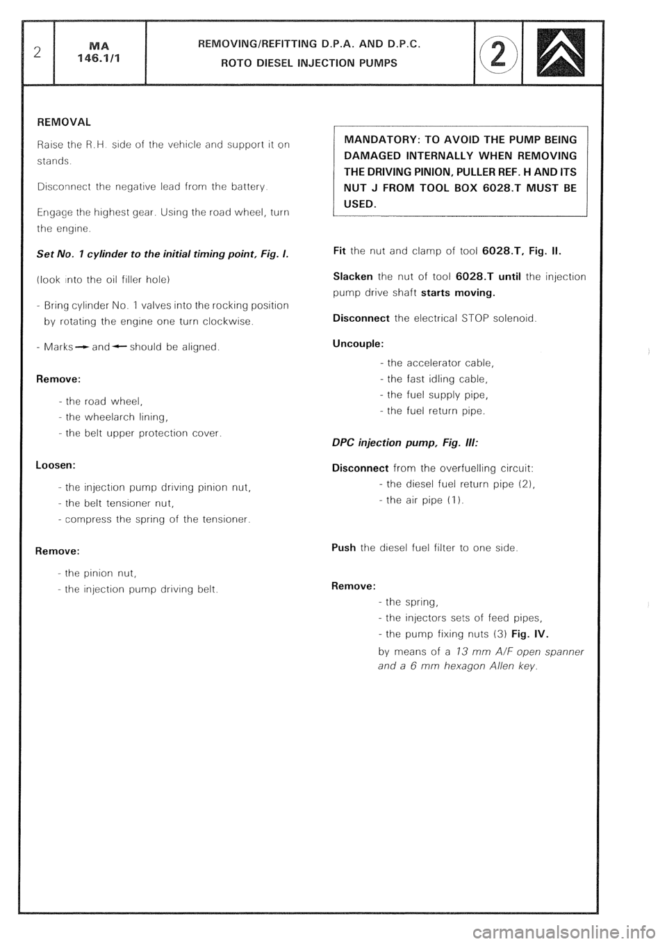
Raise the R.H side of the vehicle and support it on
stands.
Disconnect the negative lead from the battery
Engage the highest gear. Using the road wheel, turn
the engine.
Set No. I cylinder to the initial timing point, Fig. I.
(look into the oil filler hole)
- Bring cylinder No. 1 valves into the rocking position
by rotating the engine one turn clockwise.
- Marks- and- should be aligned.
Remove:
- the road wheel,
- the wheelarch lining,
- the belt upper protection cover.
Loosen:
- the injection pump drrvrng pinion nut,
- the belt tensioner nut,
- compress the spring of the tensioner.
Remove:
- the pinion nut,
- the injection pump driving belt. MANDATORY: TO AVOID THE PUMP BEING
DAMAGED INTERNALLY WHEN REMOVING
THE DRIVING PINION, PULLER REF. H AND ITS
NUT J FROM TOOL BOX 6028.T MUST BE
USED.
Fit the nut and clamp of tool 6028.T, Fig. II.
Slacken the nut of tool 6028.T until the injection
pump drive shaft starts moving.
Disconnect the electrical STOP solenoid
Uncouple:
- the accelerator cable,
- the fast idling cable,
- the fuel supply pipe,
- the fuel return pipe.
DPC injection pump, Fig. ill:
Disconnect from the overfuelling circuit:
- the diesel fuel return pipe (21,
- the air pipe (I 1.
Push the diesel fuel filter to one side
Remove:
- the spring,
- the injectors sets of feed pipes,
- the pump fixing nuts (3) Fig. IV.
by means of a 73 mm A/F open spanner
and a 6 mm hexagon Allen key.
Page 218 of 648
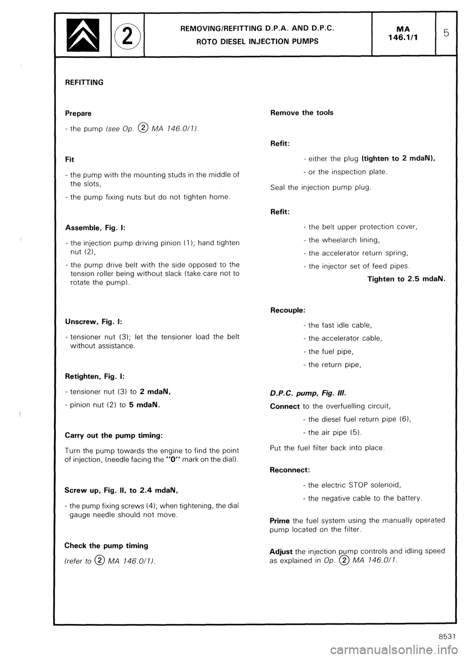
REMOVING/REFITTING D.P.A. AND D.P.C.
ROT0 DIESEL INJECTION PUMPS MA
146.1/l 5
REFITTING
Prepare
- the pump (see Op. @ MA 146.0/l/
Fit
- the pump with the mounting studs in the middle of
the slots,
- the pump fixing nuts but do not tighten home.
Assemble, Fig. I:
- the injection pump driving pinion t I); hand tighten
nut (2),
- the pump drive belt with the side opposed to the
tension roller being without slack (take care not to
rotate the pump).
Unscrew, Fig. I:
- tensioner nut (3); let the tensioner load the belt
without assistance.
Retighten, Fig. I:
- tensioner nut (3) to 2 mdaN,
- pinion nut (2) to 5 mdaN.
Carry out the pump timing:
Turn the pump towards the engine to find the point
of injection, (needle facing the “0” mark on the dial).
Screw up, Fig. II, to 2.4 mdaN,
- the pump fixing screws (4); when tightening, the dial
gauge needle should not move.
Check the pump timing (refer to @ MA 146.011)
Remove the tools
Refit:
- either the plug (tighten to 2 mdaN),
- or the inspection plate.
Seal the injection pump plug.
Refit:
- the belt upper protection cover,
- the wheelarch lining,
- the accelerator return spring,
- the injector set of feed pipes.
Tighten to 2.5 mdaN.
Recouple:
- the fast idle cable,
- the accelerator cable,
- the fuel pipe,
- the return pipe, D.P.C. pump, Fig. III.
Connect to the overfuelling circuit,
- the diesel fuel return pipe (61,
- the air pipe (5).
Put the fuel filter back into place.
Reconnect:
- the electric STOP solenoid,
- the negative cable to the battery.
Prime the fuel system using the manually operated
pump located on the filter.
Adjust the injection pump controls and idling speed
as explained in Op. @ MA 146.0/l.
8531
Page 260 of 648
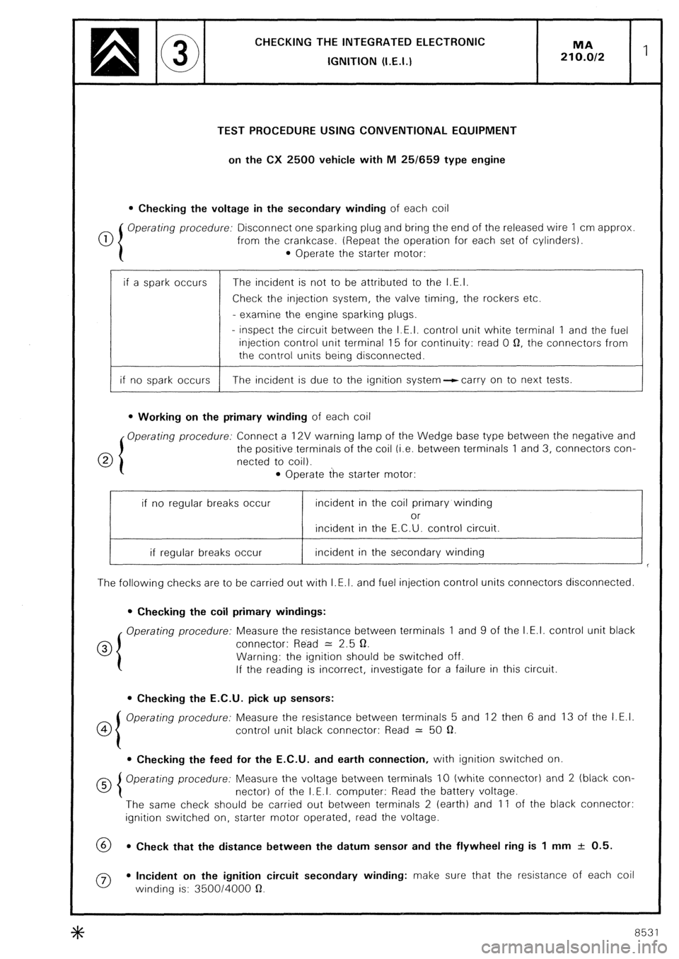
CHECKING THE INTEGRATED ELECTRONlC
IGNITION (I.E.I.)
TEST PROCEDURE USING CONVENTIONAL EQUIPMENT
on the CX 2500 vehicle with M 25/659 type engine
l Checking the voltage in the secondary winding of each coil
0 Operating procedure: Disconnect one sparking plug and bring the end of the released wire 1 cm approx
from the crankcase. (Repeat the operation for each set of cylinders).
l Operate the starter motor:
if a spark occurs The incident is not to be attributed to the I.E.I.
Check the injection system, the valve timing, the rockers etc.
- examine the engine sparking plugs.
- inspect the circuit between the I.E.I. control unit white terminal 1 and the fuel
injection control unit terminal 15 for continuity: read 0 0, the connectors from
the control units being disconnected.
if no spark occurs The incident is due to the ignition system--ccarry on to next tests.
l Working on the primary winding of each coil
Operating procedure: Connect a 12V warning lamp of the Wedge base type between the negative and
0 the positive terminals of the coil (i.e. between terminals 1 and 3, connectors con-
netted to coil).
l Operate the starter motor:
if no regular breaks occur incident in the coil primary winding
or
incident in the E.C.U. control circuit.
if regular breaks occur incident in the secondary winding
The following checks are to be carried out with I.E.I. and fuel injection control units connectors disconnected.
l Checking the coil primary windings:
Operating procedure: Measure the resistance between terminals 1 and 9 of the I.E.I. control unit black
0 connector: Read = 2.5 0.
Warning: the ignition should be switched off.
If the reading is incorrect, investigate for a failure in this circuit.
l Checking the E.C.U. pick up sensors:
co Operating procedure: Measure the resistance between terminals 5 and 12 then 6 and 13 of the I.E.I.
control unit black connector: Read = 50 a.
l Checking the feed for the E.C.U. and earth connection, with ignition switched on
Operating procedure: Measure the voltage between terminals IO (white connector) and 2 (black con-
nector) of the I.E.I. computer: Read the battery voltage.
The same check should be carried out between terminals 2 (earth) and 11 of the black connector:
ignition switched on, starter motor operated, read the voltage.
69 l Check that the distance between the datum sensor and the flywheel ring is 1 mm + 0.5.
0 l Incident on the ignition circuit secondary winding: make sure that the resistance of each coil
winding is: 350014000 a.
8531
Page 261 of 648
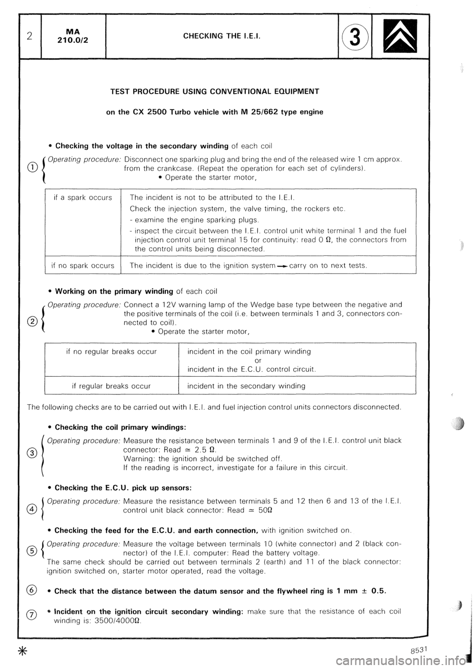
CHECKING THE I.E.I.
TEST PROCEDURE USING CONVENTIONAL EQUIPMENT
on the CX 2500 Turbo vehicle with M 25/662 type engine
0 Checking the voltage in the secondary winding of each coil
0 Operating procedure: Disconnect one sparking plug and bring the end of the released wire 1 cm approx
from the crankcase. (Repeat the operation for each set of cylinders).
0 Operate the starter motor,
if a spark occurs
if no spark occurs The incident is not to be attributed to the I.E.I.
Check the injection system, the valve timing, the rockers etc.
- examine the engine sparking plugs.
- inspect the circuit between the I.E.I. control unit white terminal 1 and the fuel
injection control unit terminal 15 for continuity: read 0 Q, the connectors from
the control units being disconnected.
The incident is due to the ignition system-carry on to next tests.
l Working on the primary winding of each coil
Operating procedure: Connect a 12V warning lamp of the Wedge base type between the negative and
the positive terminals of the coil (i.e. between terminals 1 and 3, connectors con-
netted to coil).
l Operate the starter motor,
if no regular breaks occur incident in the coil primary winding
or
incident in the E.C.U. control circuit.
if regular breaks occur incident in the secondary winding
The following checks are to be carried out with I.E.I. and fuel injection control units connectors disconnected.
0 Checking the coil primary windings:
Operating procedure: Measure the resistance between terminals 1 and 9 of the I.E.I. control unit black
0 connector: Read = 2.5 Q.
Warning: the ignition should be switched off.
If the reading is incorrect, investigate for a failure in this circuit.
l Checking the E.C.U. pick up sensors:
OI Operating procedure: Measure the resistance between terminals 5 and 12 then 6 and 13 of the I.E.I.
4
control unit black connector: Read 2: 5OQ
0 Checking the feed for the E.C.U. and earth connection, with ignition switched on.
d 5 Operating procedure: Measure the voltage between terminals 10 (white connector) and 2 (black con-
nectar) of the I.E.I. computer: Read the battery voltage.
The same check should be carried out between terminals 2 (earth) and 11 of the black connector:
ignition switched on, starter motor operated, read the voltage.
@ 0 Check that the distance between the datum sensor and the flywheel ring is 1 mm + 0.5.
0 * Incident on the ignition circuit secondary winding: make sure that the resistance of each coil
winding is: 350014OOOQ.