belt CITROEN CX 1988 Service Manual
[x] Cancel search | Manufacturer: CITROEN, Model Year: 1988, Model line: CX, Model: CITROEN CX 1988Pages: 648, PDF Size: 95.8 MB
Page 91 of 648

REMOVING AND REFITTING
THE ENGINE/GEARBOX ASSEMBLY
- 2.5 LITRE CX WITH PETROL INJECTION -
REMOVAL
Support the car on stands horizontally, Fig. I using
the three stands 6602-T, in order to facilitate the
removal of the power unit assembly and to reposition
it more easily on the stands.
Depressurize the hydraulic system.
Drain the brake accumulator.
Set the height control to the “low” position
Remove:
- the battery,
- the bonnet,
- the front wheel,
- the spare wheel
- the protection plate located under the spare wheel,
Drain the cooling circuit via the drain hose of the
radiator.
Take off the crankcase drain plug (I 1, Fig. II.
Remove the drive-shafts:
(Refer to Op @ MA.372. l/l)
Uncouple: hoses (6) and (71, Fig. IV (protecting the
alternator from water entry at “a”).
Disconnect the engine cooling fan thermal switch.
Remove the engine heat sink.
Extract, Fig. Ill:
- the screws that secure horn (2) support, passing
through the wheelarch,
- the wheelarch lining. Disconnect:
- wiring harnesses (3) from the battery positive lead,
Fig. Ill,
- the ground cable from the gearbox,
- the wiring harness from the reversing lamp switch.
Remove, Fig. Ill:
- the pressure regulator accumulator,
- pipe (4) between pressure regulator and brake accu-
mulator.
Vehicle with air conditioning option:
- the belt protective cover,
- the air conditioning compressor drive belt
Uncouple:
- the air intake casing position accelerator cable,
- the high pressure pump rubber suction pipe,
- the high pressure pump outlet pipe (5) and its attach-
ment, Fig. Ill.
Disconnect: Fig. V
- the throttle spindle switch (IO),
- knock sensor (14).
Uncouple: Fig. V
- pressure sensor pipe(91,
- supplementary air pipe (I I),
- cylinderhead cover pipe (I 21,
- breather pipe (8).
Remove suction pipe (I 3) situated between the flow-
meter and the turbocharger or between the flowme-
ter and the inlet manifold.
Page 97 of 648

le up the exhaust system. econnect, Fig. IV and V:
- connectors 11 I),
turaily aspirated engines w/th EN, fitted with
seals:
Tighten the flange to 1.6 mda
On the turbocharged engines with EH, fitted with
NEW nuts and seals:
Refit: Fig. I and II, - sensor (12) (with biue /dent mark),
- sensor (13) (with no ident mark),
- HT coil 191 cyls 1 and 4 (with yellow /dent mark),
HT coil i IO) cyls 2 and 3 (w/t/r fro markl,
- the suppressors,
- the reversing larnp switch wrring harness,
- the throttle spindle switch (141,
- knock sensor (I 8).
- flexible pipe (2) to the pressure release valve outlet,
- exhaust pipe (4) to the turbo, screws (31, distance
pieces (51,
- screw (6) and adjusting shims.
There should be a 5 mm clearance at least between
the exhaust pipe and the engine crankcase. Recouple, Fig. V and VI:
- the water hoses,
- air circurt pipes (151, (161, (17). (20) and (211,
- petrol circuit pipes (I 9),
- gear shift link rods,
- the accelerator cable.
Tighten, Fig. I and II:
- turbocharger nuts fin the correct sequence), Fig. II,
- flexible hose (2) screws (3) and nuts (I 1 to
2.5 mdaN,
- screw (6) to 5 mdaN. Fit:
- the driveshafts,
(See Op. @ MA 372-l/11
- the radiator,
- the bonnet,
- the battery,
Refit: Fig. Ill
- the pressure regulator and compressor holder (air
conditioning option) together with its shims; tigh-
ten nuts (7) to 5 mdaN. - the protection plate located under the spare
wheel.
Check the oil levels. Top up if necessary.
Vehicles with air-conditioning: Fill up the cooling circuit (wrth the heater open) and
carry out the bleeding operation.
- the compressor belt and protection cover,
- the pressure regulator accumulator, fitted with a
NEW seal,
- the HP pump outlet pope, fitted with a NEW sea/
and its fastenings (8),
- the pipe situated between the pressure regulator
and the brake accumulator, fitted with NEWseals,
- the HP pump rubber suction pipe,
- the horn. (As per Op @ MA 230.0/l/.
Bleed the front brakes.
(Refer to Op. MA 453.0/l/.
Check the gear change.
Lower the vehicle to the ground.
Page 105 of 648
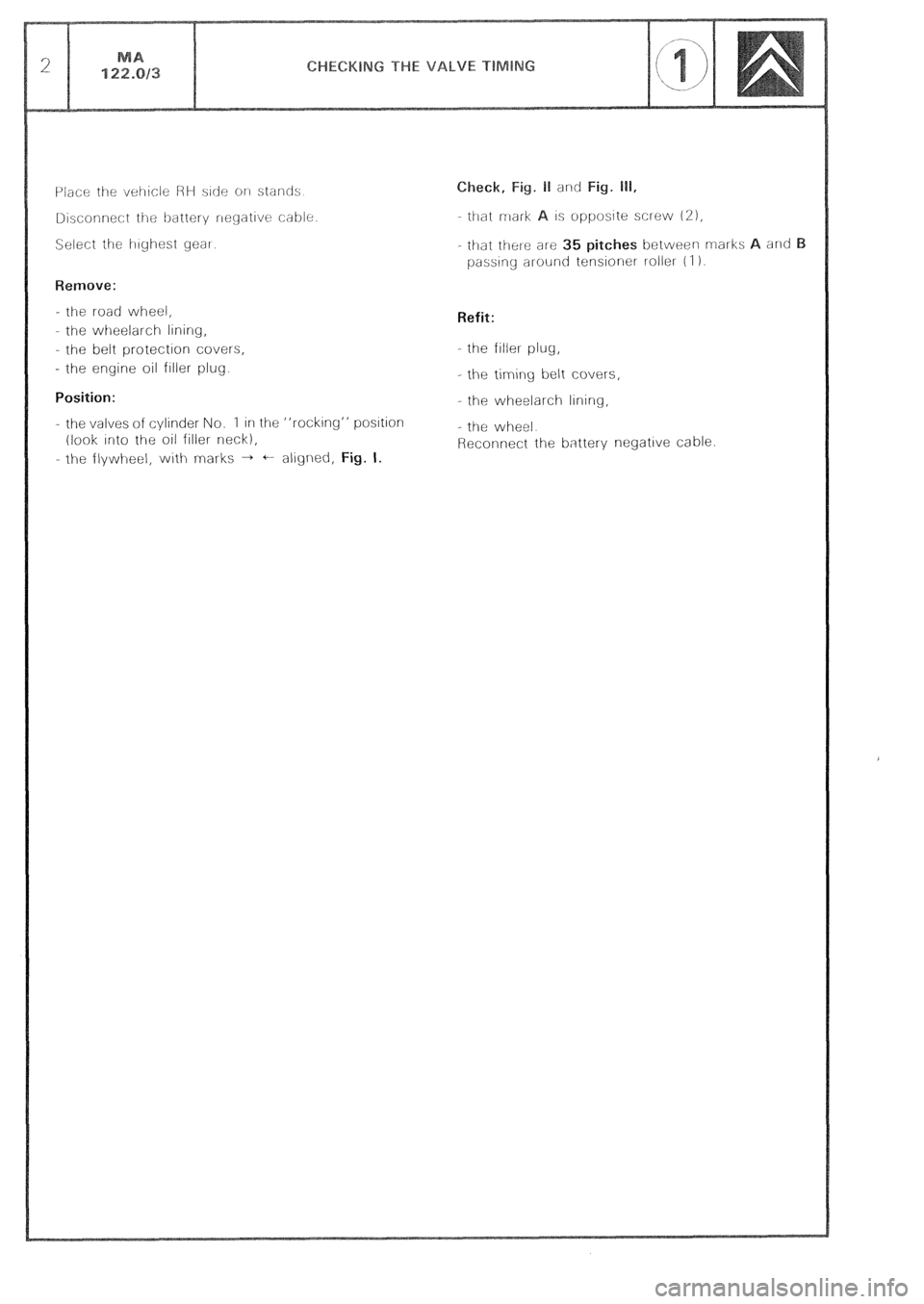
- the road wheel,
- the wheelarch lining,
the belt protection covers,
- the engine oil filler plug.
Position:
- the valves of cylinder No. 1 in the “rocking” postion
(look Into the oil filler neck),
- the flywlleel, with marks + + aligned, Fig. I. t/hat mark 1s opposite screw 121,
- ttlat the:ie ar-e 35 pitches between marks and
passing al-ounc tensioner roller- (I 1.
Refit:
- the filler plug,
- the timing belt covers,
- the wheelarch lining,
- the wheel
Reconnect the battery negative cable
Page 108 of 648
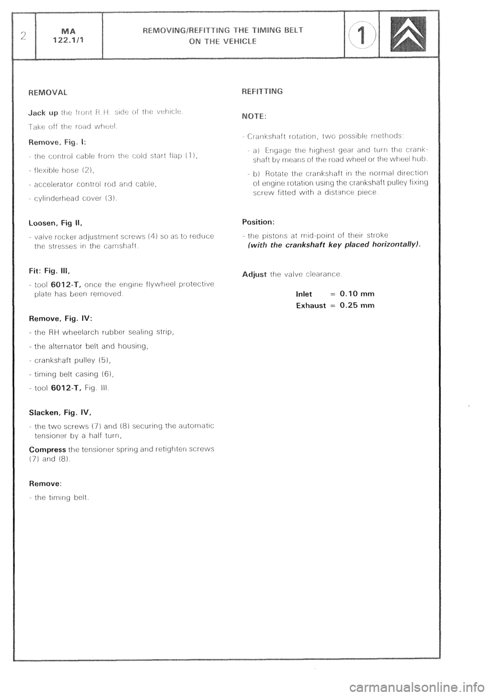
loosen, Fig II,
- valve rocket adjustrnr:nt screws (4) so as to reduce
the stresses irl the camshaft.
Fit: Fig. 111,
- tool 6012-T, once the engine flywheel protective
plate has been rernoved
Remove, Fig. IV:
- the HH wheelarch rubber sealing strtp,
- the al&l-nator belt and housing,
- crankshaft pulley (5),
- timing belt casing 161,
- tool
6012-T, Fig. III
Slacken, Fig. IV,
- the two XI-ews (7) and 18) securing the autornatlc
tensioner by a half turn,
Compress the tensioner spring and retighterl screws
(71 and 18).
Remove:
the timing belt. Crarlkshaft rotation, two pnss~ble rrrothotls
a) i-rlgage the irighest gear and tul n the clank-
shaft by means oi the road wheel OI the wheel i-tub
b) Rotate ti-le crankstlaft 1i1 the normal direction
of eqne rotation using the crankshaft pulley fixing
screw fitted with a ciistsnce piece
Position:
- the pistons at mid-point of their stroke
ith the crankshaft key placed horizontally).
djust the valve clearance
Inlet = 0.10 mm
Exhaust = 0.25 mm
Page 111 of 648
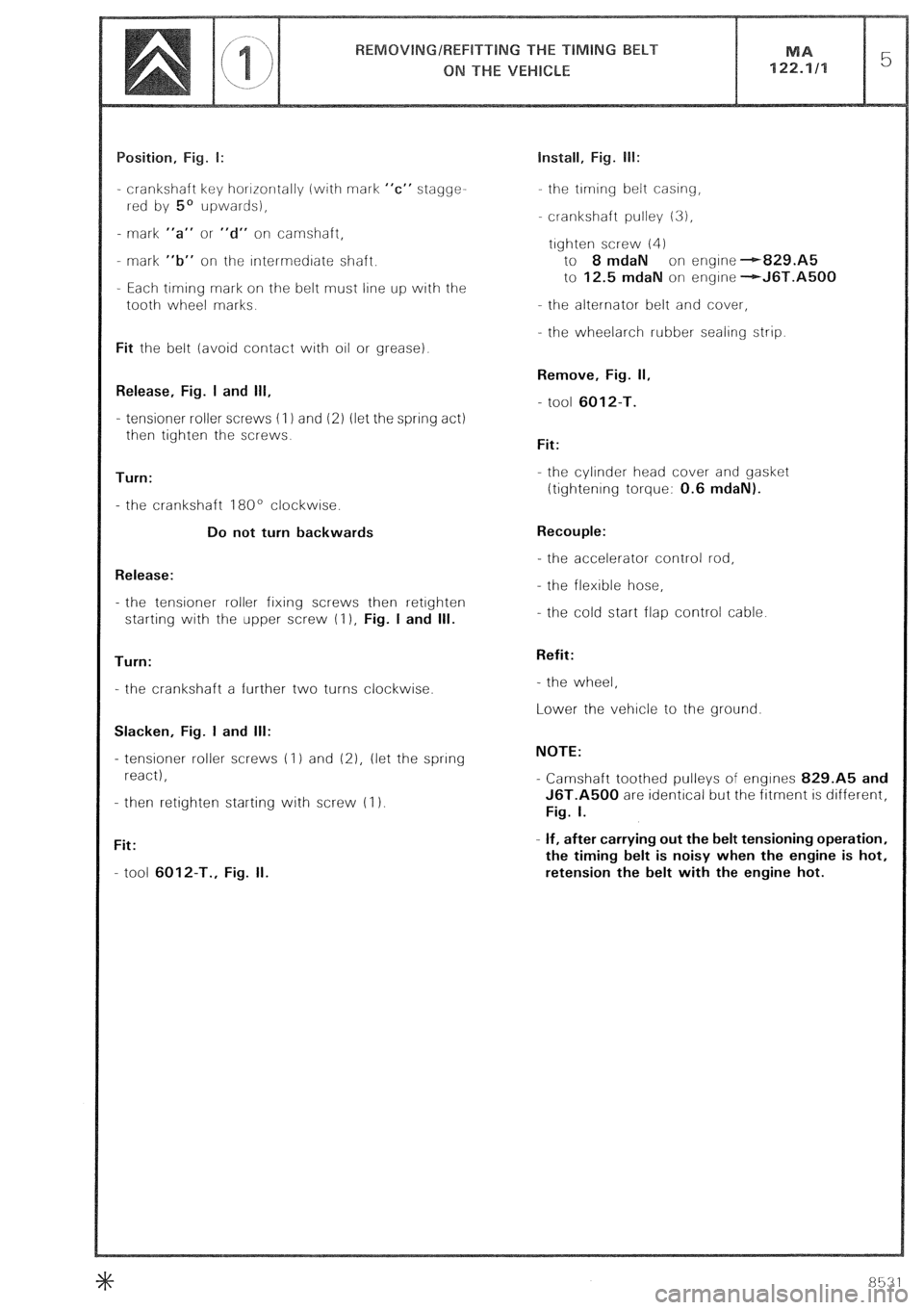
- crankshaft key horrrontally (with mark “c” stagge-
rred by 5’ upwards),
- mark “a” or “d” on camshaft,
- mark “b” on the rntermedrate shaft.
- Each timing mark on the belt must line up with the
tooth wheel marks.
Fit the belt (avoid contact with oil or grease).
Release, Fig. I and 111,
- tensioner roller screws (I 1 and 12) (let the spring act)
then tighten the screws.
Turn:
- the crankshaft 180’ clockwise.
Do not turn backwards
Release:
- the tensioner roller fixing screws then retrghten
starting with the upper screw (I ), Fig. I and Ill.
Turn:
- the crankshaft a further two turns clockwise.
Slacken, Fig. I and Ill:
- tensioner roller screws (1) and (21, (let the spring
react),
- then retighten starting with screw (I 1.
Fit:
- tool 6012-T., Fig. II. Install, Fig. lb:
the trming belt casing,
crankshaft pulley 13),
trghten screw (4)
to 8 mdaN on engine --r-829.A5
to 12.5 mdaN on engrne -+J6T.A5QQ
- the alternator belt and cover,
- the wheelarch rubber sealing strip.
Remove, Fig. II,
- tool 6012-T.
Fit:
- the cylinder head cover and gasket
ttightenrng torque: 0.6 mdaN).
Recouple:
- the accelerator control rod,
- the flexible hose,
- the cold start flap control cable.
Refit:
- the wheel,
Lower the vehicle to the ground.
NOTE:
- Camshaft toothed pulleys of engines 829.A5 and
J6T.A500 are identical but the fitment is different,
Fig. I.
- If, after carrying out the belt tensioning operation,
the timing belt is noisy when the engine is hot,
retension the belt with the engine hot.
Page 115 of 648
eIimlny belt tensioner 6028-T.K
Page 116 of 648

emove:
the I-oati Wi-l~~d,
- the wheelarch lrnrrng,
- the belt protectron covets
Position: Fig. I and II
the valves of cylrnder No. 1 rn the “rocking” ~OSI-
tion (look Into the engine 011 filler),
the flywheel wrth mar-ks- -alrgned,
- camsfraft gear wheel mark A opposite screw 12)
Loosen:
the nuts of the tensioners and compress the spring
of eacir tensloner. Hetighten the nuts.
Remove:
- injection pump belt,
- the trmrng belt
REFITTING
Fit, Fig. II:
the timrng belt- marks t-+-) and i-e-1 on the belt
should face the marks A and B on pinrons (there
are 35 pitches between A and B, passing around
the tensloner roller (I 1).
Loosen the nuts of the tensioner roller.
Install, Fig. III:
- tool 6Q28-T.K. on the roller
- the tool weight over the mark 2 of the rod, Fig 1V. Fitting the injection pump belt:
Run the engrne by 1 turn err the drrectrorr of rotation
until marks--- +- /Ino up, Fig. I
(wrth cylinder No 1 at the rnrtral trmrng
point)
Setting the pump to the injection point:
refer to Op @ MA. 146-011
Fit the InJectron purnf, drrvrng belt with the srde oppo-
site the roller, trght.
Slacken the roller nut. Let the roller- spring react
Tighten the rnut to 2 mdaN.
Rotate the engine by 2 turns in the direction of nor-
rnal rotation and check the pump timrng.
Remove the tools
Start the engine Warrn it up until the electric cooling
fans operate.
Retension the belt while the engine is hot, Fig. IV
Refit:
- the protectron covers,
- the wheelarch lining,
the road wheel
Page 119 of 648
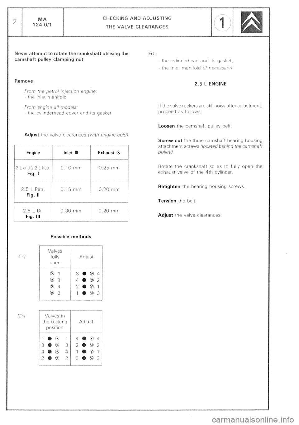
Engine Inlet Exhaust @
2 I. did 2 2 L Pet1
Fig. I
0 IO rnrr 0.25 rrirr
2.5 l- Petr.
Fig. II
0.15 mm 0.20 mm
Possible methods
1 “I
%“I
Valves
fully
open
64 1
@3
ciD4
69%
Adjust
3 694
4 692
2
@ 1
1 ‘83
Valves in
the r-ocklng
position Adjust If the valve rockers arc? sl~l! noIs\; after adystment,
proceec as follows
Screw out lhe three carmshaft bearing houslng
attachment screws iiocared beii/no’ rhe
carnshfl
pu//e)/i
Retighten
the beal-ing housing screws
Tension the belt.
Adjust the valve clearances.
Page 216 of 648
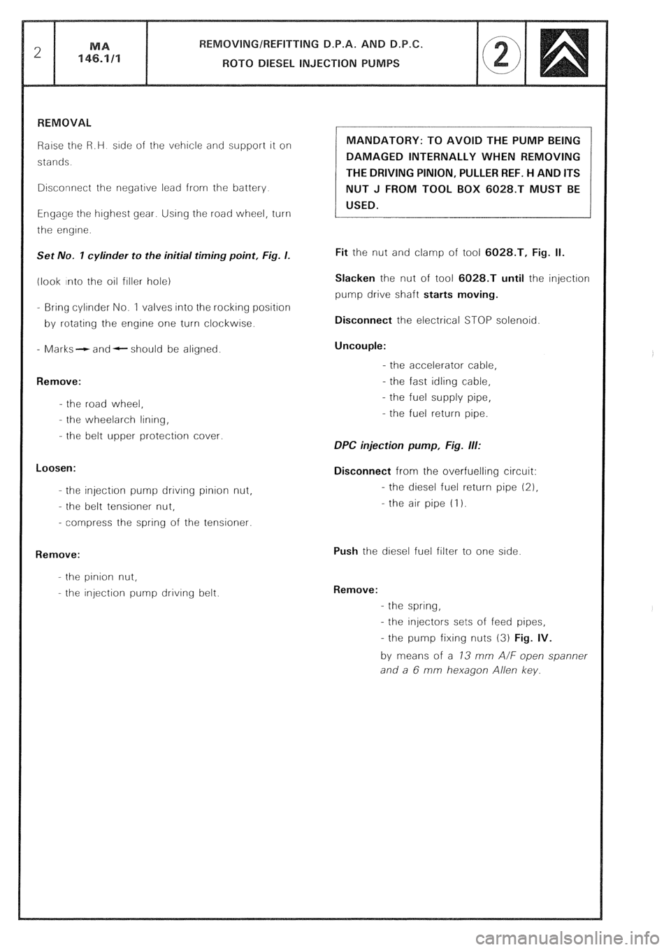
Raise the R.H side of the vehicle and support it on
stands.
Disconnect the negative lead from the battery
Engage the highest gear. Using the road wheel, turn
the engine.
Set No. I cylinder to the initial timing point, Fig. I.
(look into the oil filler hole)
- Bring cylinder No. 1 valves into the rocking position
by rotating the engine one turn clockwise.
- Marks- and- should be aligned.
Remove:
- the road wheel,
- the wheelarch lining,
- the belt upper protection cover.
Loosen:
- the injection pump drrvrng pinion nut,
- the belt tensioner nut,
- compress the spring of the tensioner.
Remove:
- the pinion nut,
- the injection pump driving belt. MANDATORY: TO AVOID THE PUMP BEING
DAMAGED INTERNALLY WHEN REMOVING
THE DRIVING PINION, PULLER REF. H AND ITS
NUT J FROM TOOL BOX 6028.T MUST BE
USED.
Fit the nut and clamp of tool 6028.T, Fig. II.
Slacken the nut of tool 6028.T until the injection
pump drive shaft starts moving.
Disconnect the electrical STOP solenoid
Uncouple:
- the accelerator cable,
- the fast idling cable,
- the fuel supply pipe,
- the fuel return pipe.
DPC injection pump, Fig. ill:
Disconnect from the overfuelling circuit:
- the diesel fuel return pipe (21,
- the air pipe (I 1.
Push the diesel fuel filter to one side
Remove:
- the spring,
- the injectors sets of feed pipes,
- the pump fixing nuts (3) Fig. IV.
by means of a 73 mm A/F open spanner
and a 6 mm hexagon Allen key.
Page 218 of 648
REMOVING/REFITTING D.P.A. AND D.P.C.
ROT0 DIESEL INJECTION PUMPS MA
146.1/l 5
REFITTING
Prepare
- the pump (see Op. @ MA 146.0/l/
Fit
- the pump with the mounting studs in the middle of
the slots,
- the pump fixing nuts but do not tighten home.
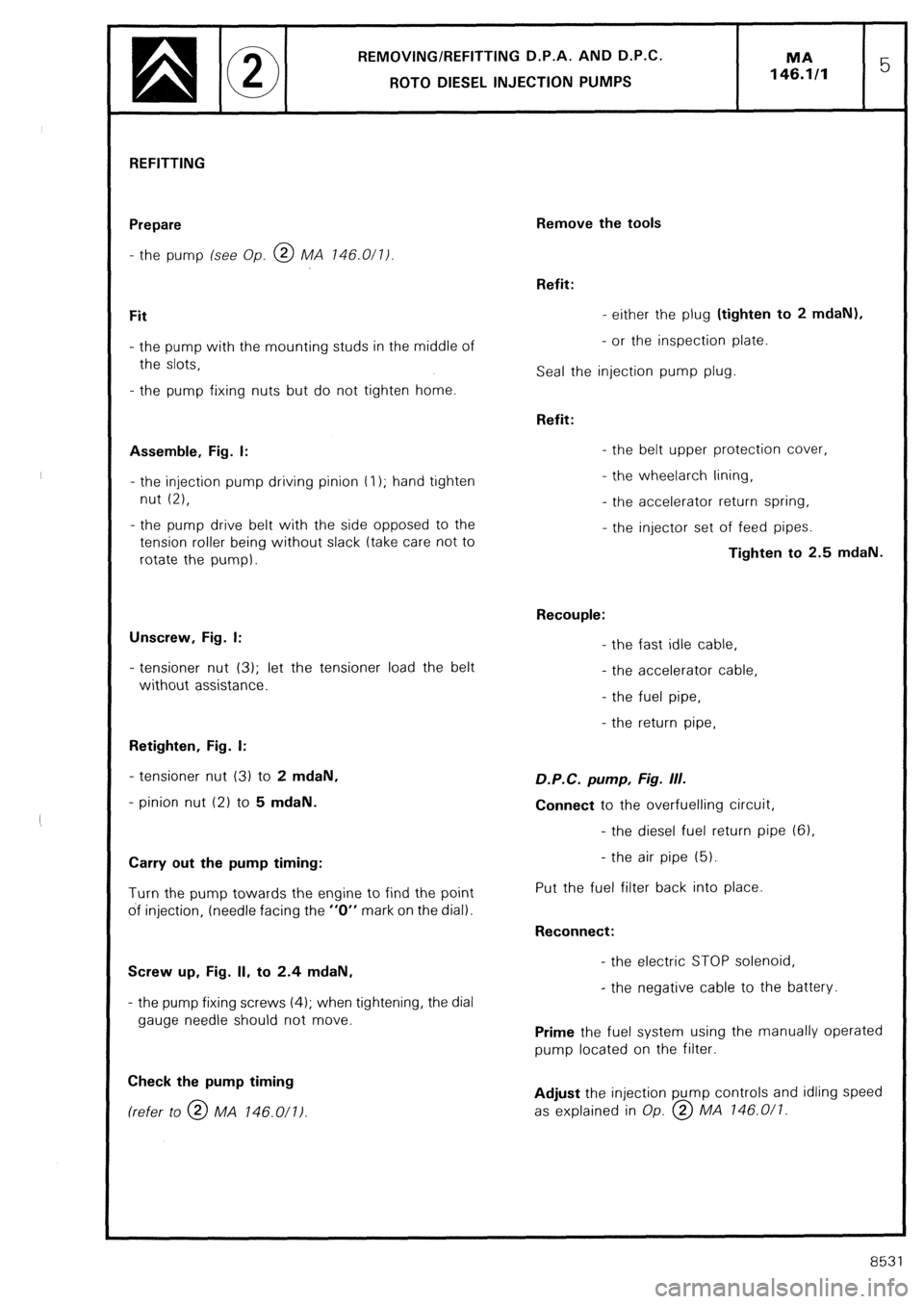
Assemble, Fig. I:
- the injection pump driving pinion t I); hand tighten
nut (2),
- the pump drive belt with the side opposed to the
tension roller being without slack (take care not to
rotate the pump).
Unscrew, Fig. I:
- tensioner nut (3); let the tensioner load the belt
without assistance.
Retighten, Fig. I:
- tensioner nut (3) to 2 mdaN,
- pinion nut (2) to 5 mdaN.
Carry out the pump timing:
Turn the pump towards the engine to find the point
of injection, (needle facing the “0” mark on the dial).
Screw up, Fig. II, to 2.4 mdaN,
- the pump fixing screws (4); when tightening, the dial
gauge needle should not move.
Check the pump timing (refer to @ MA 146.011)
Remove the tools
Refit:
- either the plug (tighten to 2 mdaN),
- or the inspection plate.
Seal the injection pump plug.
Refit:
- the belt upper protection cover,
- the wheelarch lining,
- the accelerator return spring,
- the injector set of feed pipes.
Tighten to 2.5 mdaN.
Recouple:
- the fast idle cable,
- the accelerator cable,
- the fuel pipe,
- the return pipe, D.P.C. pump, Fig. III.
Connect to the overfuelling circuit,
- the diesel fuel return pipe (61,
- the air pipe (5).
Put the fuel filter back into place.
Reconnect:
- the electric STOP solenoid,
- the negative cable to the battery.
Prime the fuel system using the manually operated
pump located on the filter.
Adjust the injection pump controls and idling speed
as explained in Op. @ MA 146.0/l.
8531