lock CITROEN CX 1988 Service Manual
[x] Cancel search | Manufacturer: CITROEN, Model Year: 1988, Model line: CX, Model: CITROEN CX 1988Pages: 648, PDF Size: 95.8 MB
Page 17 of 648
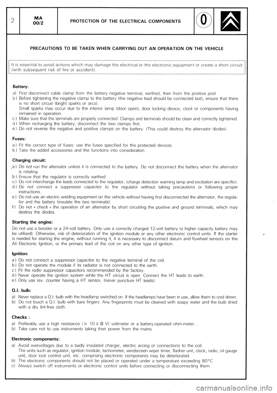
PROTECTION OF THE ELECTRICAL COMPONENTS
PRECAUTIONS TO BE TAKEN WHEN CARRYING OUT AN OPERATION ON THE VEHICLE
It is essential to avoid actrons which may damage the electrical or the electronic equipment or create a short circuit
(wrth subsequent risk of fire or accident).
Battery:
a) First disconnect cable clamp from the battery negative terminal, earthed, then from the positive post.
b 1 Before tightening the negative clamp to the battery (the negative lead should be connected last), ensure that there
is no short circuit (bright sparks or arcs).
Small sparks may occur due to the interior lamp (door open), door locking device, clock or components having
remained in operation.
c 1 Make sure that the terminals are properly connected. Clamps and terminals should be clean and correctly tightened.
d ) When recharging the battery, disconnect the two clamps first.
e) Do not reverse the negative and positive clamps on the battery. (This could destroy the alternator diodes).
Fuses:
a 1 Fit the correct type of fuses: use the fuses specified for the protected devices
b 1 Take the added accessories and the functions into consideration.
Charging circuit:
,a 1 Do not run the alternator unless it is connected to the battery. Do not disconnect the battery when the alternator
is rotating.
b 1 Ensure that the regulator is correctly earthed.
c ) Do not interchange the leads connected to the regulator, (charge detection warning lamp and excitation are specific).
d ) Do not connect a suppressor capacitor to the regulator without taking precautions or following proper
instructions.
e 1 Do not use an electric welding equipment on the vehicle without having first disconnected the alternator, the regula-
tor and the battery (insulate the two terminals).
f 1 Do not R check )) the operation of an alternator by short circuiting the positive and ground terminals, which may
destroy the diodes.
Starting the engine:
Do not use a booster or a 24-volt battery. Only use a correctly charged 12-volt battery (a higher capacity battery may
be utilised). Otherwise, risk of deterioration of the ignition module or any other electronic control units. If the starter
is needed for starting the engine, without running it, it is necessary to disconnect datum and flywheel sensors on the
All Electronic Ignition, or the primary lead of the coil on any other type of ignition.
Ignition:
a 1 Do not connect a suppressor capacitor to the negative terminal of the coil.
b 1 Do not operate the module if its radiator is not connected to the earth.
c 1 Fit the radio suppressor capacitors recommended by the factory.
d 1 Never operate the ignition system while the HT circuit is open. Connect the HT leads to earth
e) Only use rev. counter having a HT sensor, (never puncture HT leads).
0.1. bulb:
a) Never replace a 01. bulb with the headlamp switched on. If the headlamps have been in use, allow them to cool down.
b) Do not touch a 0.1. bulb with bare fingers. Any fingerprints must be cleaned with soapy water and the bulb dried
with a dry lint-free cloth.
Checks :
a) Preferably use a high resistance (> 10 k Q VI voltmeter or a battery-operated ohm-meter
b) Take care not to use instruments taking their power from the mains.
Electronic components:
a) Avoid overvoltages due to a badly insulated charger, electric arcing or connections to the coil.
The units such as regulator, ignition module, tachometer, windscreen wiper timer, flasher unit, clock, radio, oil gauge
unit, door lock control unit, etc. comprising electronic components may be deteriorated.
b) The electronic components should not be placed or operated under a temperature exceeding 80°C.
c) Always switch off instruments or electronic control units before connecting or disconnecting them.
‘
Page 19 of 648
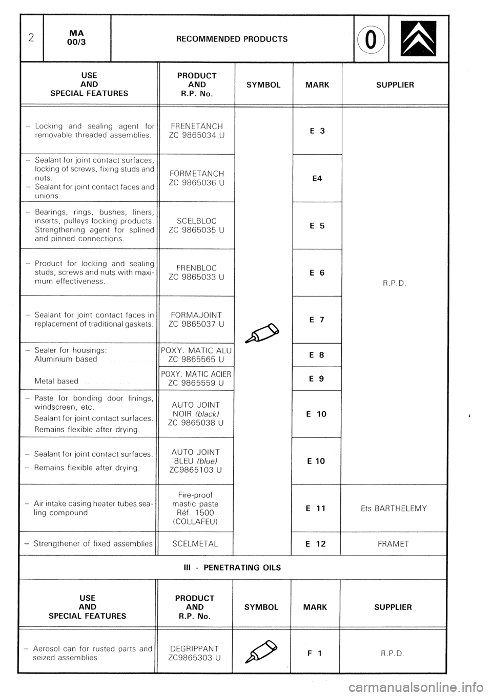
RECOMMENDED PRODUCTS
AND SUPPLIER
SPECIAL FEATURES
-- Lockrng and sealrng agent for FRENETANCH
removable threaded assemblies.
ZC 9865034 U
nuts. FORMETANCH
ZC 9865036 U
- Sealant for oint contact faces an
- Bearings, rings, bushes, liners,
inserts, pulleys locking products.
Strengthening agent for splined ZC 9865035 U
-- Product for locking and sealing
studs, screws and nuts with maxi-
ZC 9865033 U
mum effectiveness.
- Sealant for joint contact faces in FORMAJOINT
replacement of traditional gaskets. ZC 9865037 U
- Paste for bonding door linings,
windscreen, etc. AUTO JOINT
Sealant for joint contact surfaces.
ZC 9865038 U
- Sealant for joint contact surfaces. AUTO JOINT
- Remains flexible after drying.
- Air intake casing heater tubes sea-
ling compound Ets BARTHELEMY
SCELMETAL FRAM ET
III - PENETRATING OILS
AND SUPPLIER
SPECIAL FEATURES
- Aerosol can for rusted parts and DEGRIPPANT
seized assemblies ZC9865303 U
Page 20 of 648
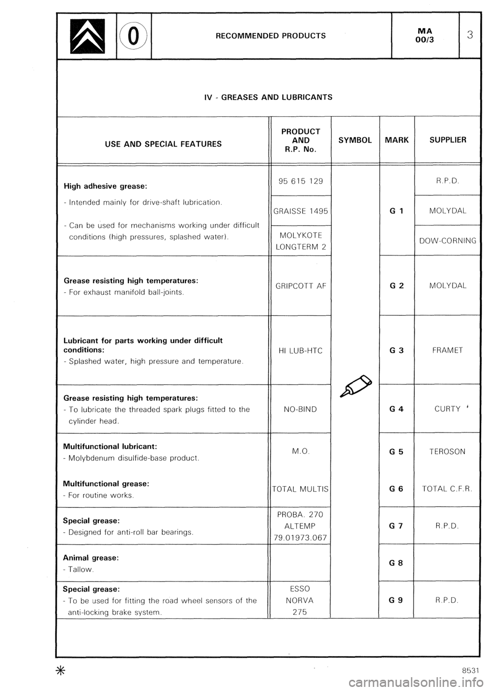
RECOMMENDED PRODUCTS
IV - GREASES AND LUBRICANTS
PRODUCT
USE AND SPECIAL FEATURES AND SYMBOL MARK SUPPLIER
R.P. No.
High adhesive grease: 95 615 129 R.P.D.
- Intended mainly for drive-shaft lubrication.
GRAISSE 1495 Gl MOLY DAL
- Can be used for mechanisms working under difficult
conditions (high pressures, splashed water). MOLYKOTE
LONGTERM 2 DOW-CORNING
Grease resisting high temperatures:
GRIPCOTT AF G2
- For exhaust manifold ball-joints. MOLYDAL
Lubricant for parts working under difficult
conditions:
HI LUB-HTC G3 FRAM ET
- Splashed water, high pressure and temperature.
Grease resisting high temperatures:
- To lubricate the threaded spark plugs fitted to the NO-BIND G4 CURTY *
cylinder head.
Multifunctional lubricant:
M.O.
G5
- Molybdenum disulfide-base product. TEROSON
Multifunctional grease:
- For routine works. TOTAL MULTIS G6 TOTAL C.F.R.
Special grease: PROBA. 270
ALTEMP G7 R.P.D.
- Designed for anti-roll bar bearings.
79.01973.067
Animal grease:
- Tallow. GB
Special grease: ESSO
- To be used for fitting the road wheel sensors of the NORVA G9 R.P.D.
anti-locking brake system. 275
8531
Page 29 of 648
5
B
e0
.
we? ,--
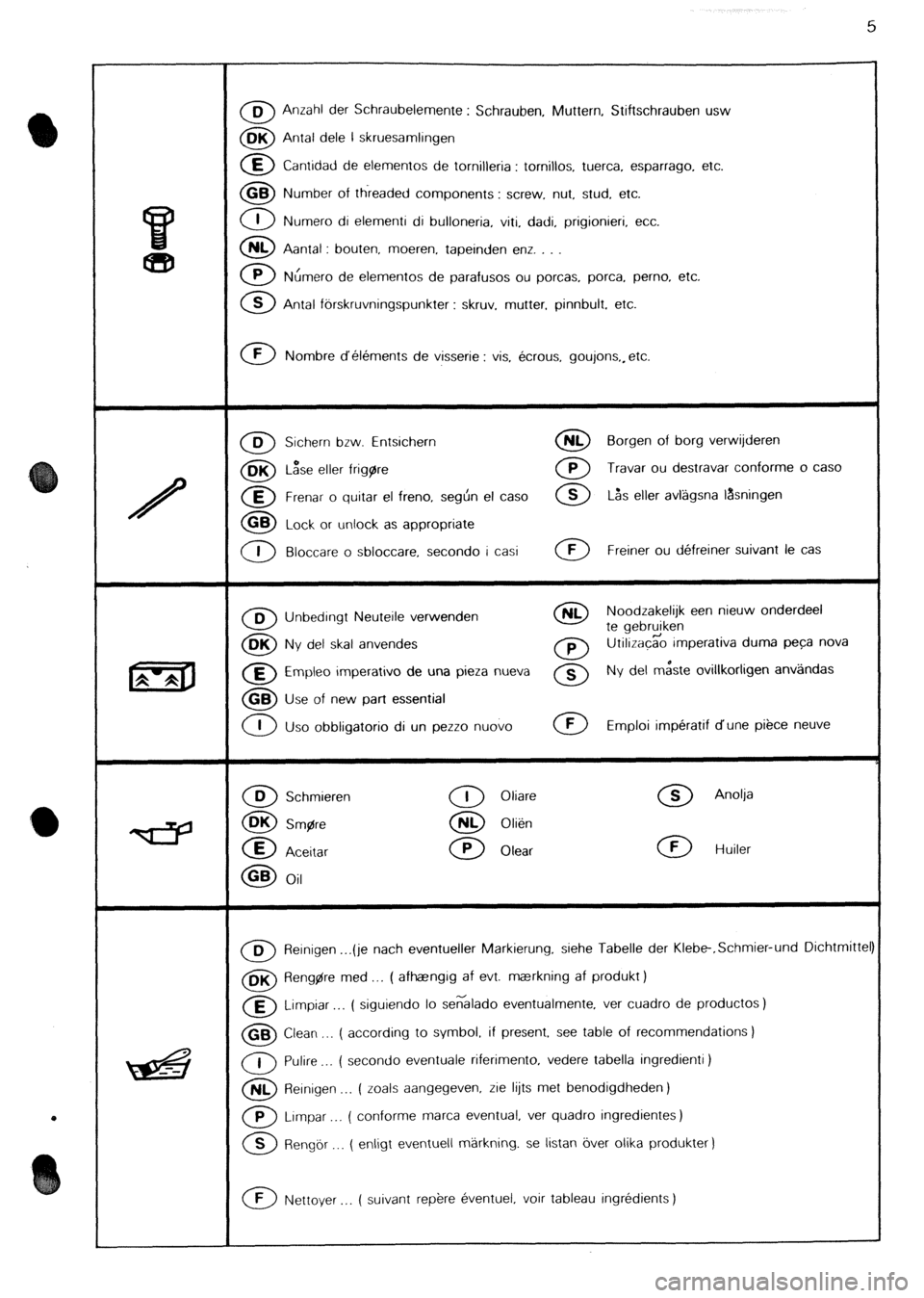
0 0 Anzahl der Schraubelemente : Schrauben, Muttern, Stiftschrauben usw
0 BK Antal dele l skruesamlingen
0 E Cantidad de elementos de tornijleria : tomillos, tuerca. esparrago, etc.
0 GB Number of threaded components : screw, nut, stud, etc.
0 1 Numero di elementi di bulloneria, viti, dadi, prigionieri, etc.
0 NL Aantal : bouten, moeren. tapeinden enz. . .
0 P Nhmero de elementos de parafusos ou porcas, porca, perno, etc.
0 B Antal fbrskruvningspunkter : skruv. mutter, pinnbult. etc.
0 F Nombre d’elements de visserie : vis, ecrous, goujons,, etc.
0 D Sichern bzw. Entsichern 0 NL Borgen of borg verwijderen
0 BK L&e eller frigare 0 P Travar ou destravar conforme o case
0 E Frenar o quitar el freno, seghn el case 0 S L&s eller avlagsna lasningen
0 GB Lock or unlock as appropriate
0 I Bloccare o sbloccare, second0 i casi 0 F Freiner ou defreiner suivant le cas
0 B Unbedingt Neuteile verwenden 0 NL Noodzakelijk een nieuw onderdeel
0
te gebruiken OK
Ny del skal anvendes 0 P Utilizacgo imperativa duma peca nova
0 E Empleo imperativo de una pieza nueva 0 s Ny del m&te ovillkorligen anv;ilndas
0 GB Use of new part essential
0 I
Uso obbligatorio di un pezzo nuovo 0 F Emploi imperatif dune piece neuve
0 D Schmieren
0 OK Smgre
0 E
Aceitar
0 GB Oil
0 I Oliare
0 NL Olien
0 P Olear
0 S Anolja
0 F Huiler
m Reinigen . ..(je nach eventueller Markierung. siehe Tabelle der Klebe-.Schmier-und Dichtmittel
0 BK Aeng$re med ,.. ( afhaangrg af evt. maerkning af produkt )
a Limpiar ( siguiendo lo se6lado eventualmente, ver cuadro de productos)
0 GB Clean ,.. ( according to symbol. if present, see table of recommendations )
0 I Pulire . . . ( second0 eventuale riferimento, vedere tabella ingredienti )
0 NL Reinigen _.. ( zoals aangegeven, rie lijts met benodigdheden)
0 P Lrmpar . ( conforme marca eventual, ver quadro ingredientes)
0 S Rengor __. ( enligt eventuell markning. se listan over olika produkter )
0 F Nettoyer ( suivant rep&e eventuel, voir tableau ingredients )
Page 90 of 648
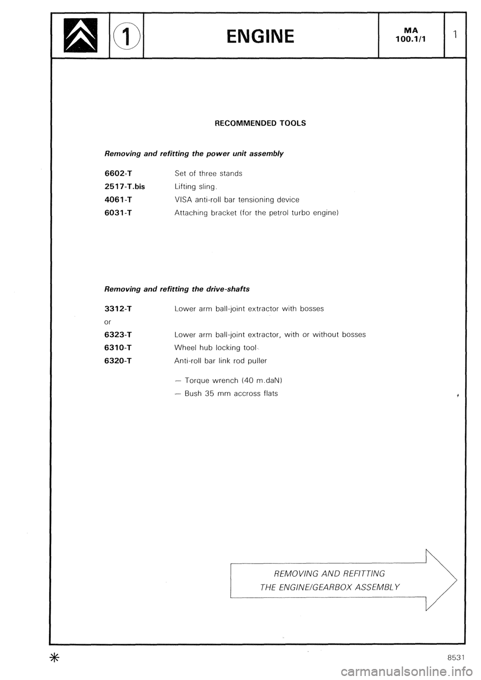
RECOMMENDED TOOLS
Removing and refitting the power unit assembly 6602-T
2517-T.bis
406 1 -T
6031 -T
Set of three stands
Lifting sling.
VISA anti-roll bar tensioning device
Attaching bracket (for the petrol turbo engine)
Removing and refitting the drive-shafts 3312-T
or 6323-T
6310-T
6320-T
Lower arm ball-joint extractor with bosses
Lower arm ball-joint extractor, with or without bosses
Wheel hub locking tool.
Anti-roll bar link rod puller
- Torque wrench (40 m.daN)
- Bush 35 mm accross flats
+K 8531
Page 102 of 648
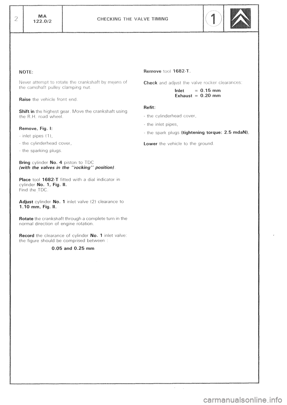
Raise ihe vei-~cle front end
Shift in the i-\~yi-\est gear. Move the crankshaft using
t!le R.H. road wheel.
Remove, Fig. I:
- inlet pipes (I 1,
- tilt: cyllnderlleati CoveI,
- the sparkIng plugs
o. 4 piston to TDC
(with the valves in the “rocking” position).
Place tool 1682-T fitted with a dial indicator In
cylinder No. 1, Fig. II.
Firlti ihe TDC.
Adjust cylinder No. 1 lrllel valve (2) clearance to
1.10 mm, Fig. II.
Rotate the cl-ankshaft through a complete turn In the
normal direction of engine rotation.
Record the clearance of cylirlder No. 1 inlet valve:
the figure should be comprised between :
0.05 and 0.25 mm eck and adlust ihe valve locker clearances.
Inlet = 0.15 mm
Exhaust = 0.20 mm
Refit:
- the cylinderhead cover,
the inlet pipes,
- the spark plugs (tightening torque: 2.5 mdaN),
Lower the vehicle to the ground
Page 107 of 648
Toothed sector for locking the engine flywheel REMOVING/REFITTING THE TIMING
BUT, ON THE VEHICLE
---____ .-
Page 111 of 648
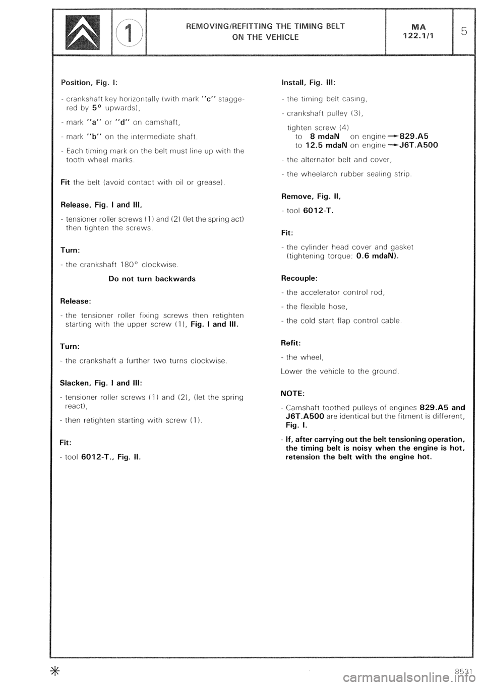
- crankshaft key horrrontally (with mark “c” stagge-
rred by 5’ upwards),
- mark “a” or “d” on camshaft,
- mark “b” on the rntermedrate shaft.
- Each timing mark on the belt must line up with the
tooth wheel marks.
Fit the belt (avoid contact with oil or grease).
Release, Fig. I and 111,
- tensioner roller screws (I 1 and 12) (let the spring act)
then tighten the screws.
Turn:
- the crankshaft 180’ clockwise.
Do not turn backwards
Release:
- the tensioner roller fixing screws then retrghten
starting with the upper screw (I ), Fig. I and Ill.
Turn:
- the crankshaft a further two turns clockwise.
Slacken, Fig. I and Ill:
- tensioner roller screws (1) and (21, (let the spring
react),
- then retighten starting with screw (I 1.
Fit:
- tool 6012-T., Fig. II. Install, Fig. lb:
the trming belt casing,
crankshaft pulley 13),
trghten screw (4)
to 8 mdaN on engine --r-829.A5
to 12.5 mdaN on engrne -+J6T.A5QQ
- the alternator belt and cover,
- the wheelarch rubber sealing strip.
Remove, Fig. II,
- tool 6012-T.
Fit:
- the cylinder head cover and gasket
ttightenrng torque: 0.6 mdaN).
Recouple:
- the accelerator control rod,
- the flexible hose,
- the cold start flap control cable.
Refit:
- the wheel,
Lower the vehicle to the ground.
NOTE:
- Camshaft toothed pulleys of engines 829.A5 and
J6T.A500 are identical but the fitment is different,
Fig. I.
- If, after carrying out the belt tensioning operation,
the timing belt is noisy when the engine is hot,
retension the belt with the engine hot.
Page 113 of 648
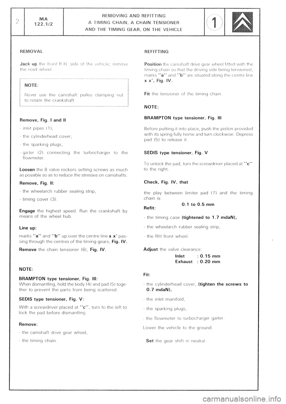
yaltot 12) connectiriy iije turbocihaiger to the
flowrneter.
Loosen the 8 valve rockers setting screws as rnuci-1
as possible so as to reduce the stresses oli camshafts
Remove, Fig. II:
the wheelarch rubber sealing strip,
- tlrmng cover (3).
Engage lhe highest speed. Run the cl-ankshaft by
means of the wheel hub.
Line up:
rnarks “a” and “b” UP over the cenlre line x x’ pas-
sing through the centres of the tlrrring gears,
Fig. IV.
Remove
the chain tensioner (cj), Fig. IV.
NOTE:
BRAMPTON type tensioner, Fig. III:
When dismantling, hold the body iii) and pad (5) togc-
ther to prevent the parts from being scatter&
SEDlS type tensioner, Fig. V:
With a screwdrlver placed at “c”, turn to the left io
lock the pad before disrnarltllrlg.
Remove:
the carnshaft drive gear- wheel,
the tlrnlr-ig chain
NOTE:
BRAMPTON type tensioner, Fig. Ill
Before putting 11 irrlo i.)ir!ce, push the pistorl provided
with 11s spring fully home a~rtl turn clockwise Depress
pad (51 to release it
SEDIS type tensioner, Fig. V
1-o unlock the pad, turn tile sclewdrlver placed at “c”
to the right
Check, Fig. IV, that
the play between limiter pad (7) and the tlmng
chain IS.
Refit: 0.1 to 0.5 mm
-.
the timing case (tightened to 1.7 mdaN),
the wheelarch rubber sealing strip,
the HH front wheel.
Adjust the valve clearance:
Inlet : 0.15 mm
Exhaust : 0.20 mm
Fit:
the cylinderhead cover, (tighten the screws to
0.7 mdaN),
the Iniot rnanlfold,
he spai-king pluys,
the flowmeter to iurbocilarycr yalter
[Lower the vehicle to the ground
Page 206 of 648
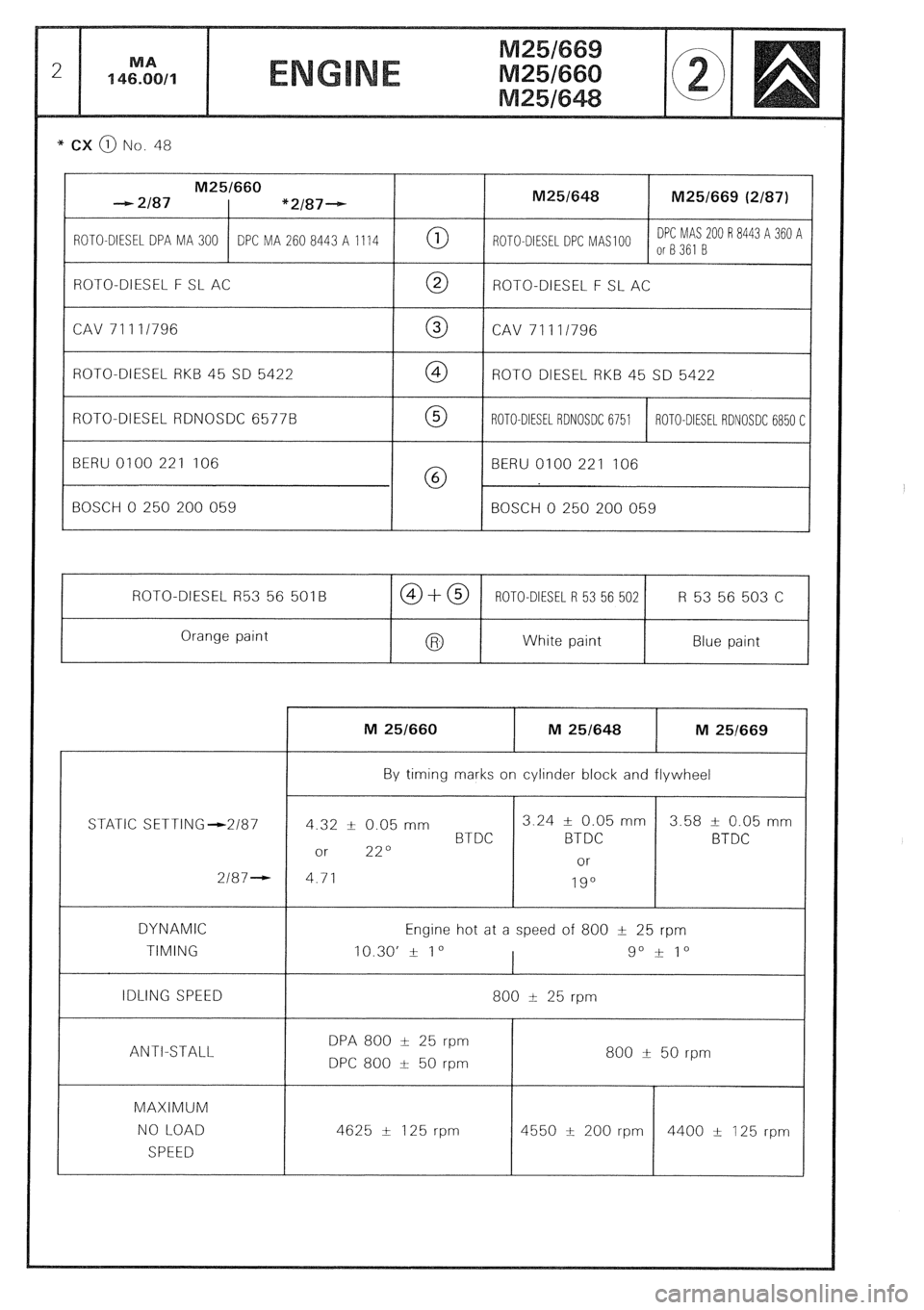
* CX @ No. 48
M25/660
- 2187 “2/87-- M25/648 M25/669 (2/87)
ROTO-DIESEL DPA MA 300 DPC MA 260 8443 A 1114 0 ROTO-DIESEL DPC MAS 100 DPC MAS 200 R 8443 A 360 A
or8361 B
ROTO-DIESEL F SL AC
0 ROTO-DIESEL F SL AC
CAV 71111796 0 CAV 71111796
ROTO-DIESEL RKB 45 SD 5422 @ ROT0 DIESEL RKB 45 SD 5422
ROTO-DIESEL RDNOSDC 6577B 0 ROTO-DIESEL RDNOSDC 6751 ROTO-DIESEL RDNOSDC 6850 C
BERU 0100 221 106
@ BERU 0100 221 106
BOSCH 0 250 200 059 BOSCH 0 250 200 059
ROTO-DIESEL R53 56 501B CO+@ ROTO-DIESEL R 53 56 502 R 53 56 503 C
Orange paint
White paint Blue paint
STATIC SETTING-2187
2187-
DYNAMIC
TIMING
IDLING SPEED
ANTI-STALL
MAXIMUM
NO LOAD
SPEED M 251660 M 25/648 M 251669
By timing marks on cylinder block and flywheel
4 12 k 0.05 mm 3.24 f 0.05 mm 3.58 t- 0.05 mm
BTDC BTDC BTDC
or 22O
or
4.71
19”
Engine hot at a speed of 800 t 25 rpm
10.30’ + 1 o
I go i 1”
800 I 25 rpm
DPA 800 t 25 rpm
DPC 800 t 50 rpm 800 & 50 rpm
4625 & 125 rpm
r
4400 + 125 rpm