coolant temperature CITROEN CX 1988 Service Manual
[x] Cancel search | Manufacturer: CITROEN, Model Year: 1988, Model line: CX, Model: CITROEN CX 1988Pages: 648, PDF Size: 95.8 MB
Page 194 of 648

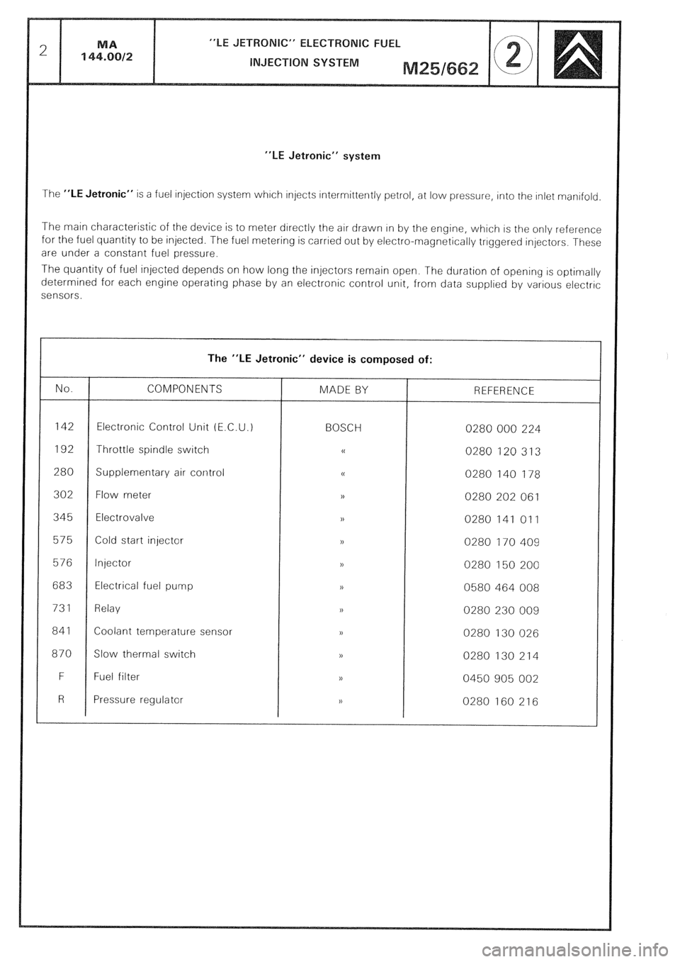
“LE Jetronic” system
The “LE Jetronic” is a fuel injection system whrch injects intermittently petrol, at low pressure, into the Inlet manrfold
The main characteristic of the device is to meter directly the air drawn In by the engine, which is the only reference
for the fuel quantity to be injected. The fuel metering is carried out by electro-magnetically triggered injectors. These
are under a constant fuel pressure.
The quantity of fuel injected depends on how long the injectors remain open. The duration of opening IS optimally
determined for each engine operating phase by an electronic control unit, from data supplied by various electric
sensors.
The “LE Jetronic” device is composed of:
No. COMPONENTS MADE BY REFERENCE
142 Electronic Control Unit (E.C.U.) BOSCH 0280 000 224
192 Throttle spindle switch 0
0280 120 313
280 Supplementary air control u
0280 140 178
302 Flow meter ,)
0280 202 061
345 Electrovalve ,,
0280 141 011
575 Cold start injector n
0280 170 409
576 Injector >,
0280 150 200
683 Electrical fuel
pump 1,
0580 464 008
731 Relay >,
0280 230 009
841 Coolant temperature sensor 1)
0280 130 026
870 Slow thermal switch ,>
0280 130 214
F Fuel filter ),
0450 905 002
R Pressure regulator ,)
0280 160 216
Page 393 of 648

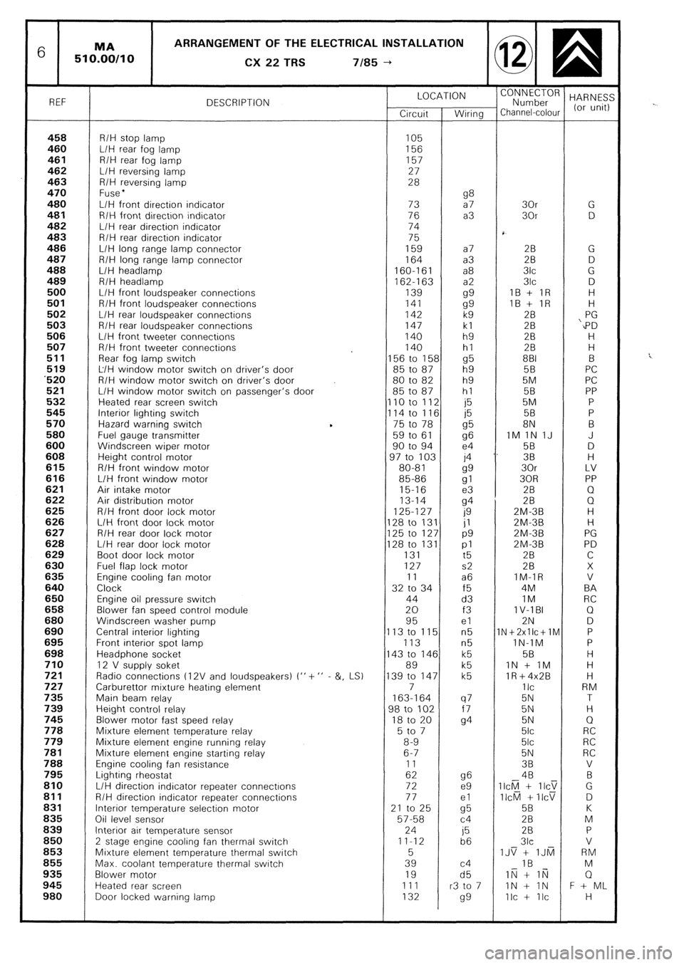
6 ARRANGEMENT OF THE ELECTRICAL INSTALLATION
CX
22 TRS 7185 --)
REF DESCRIPTION LOCATION
“;;;;;roR HARNES:
Circuit Wiring Channel-colour (or unit)
458 R/H stop lamp 105 460 L/H rear fog lamp 156 461 R/H rear fog lamp 157
462 L/H reversing lamp 27
463 R/H reversing lamp 28
470 Fuse l 480 g8 L/H front direction indicator 73 a7 30r G 481 R/H front direction indicator 76 a3 30r D 482 L/H rear direction indicator 74
483 R/H rear direction indicator 75
486 L/H long range lamp connector 159 a7 28 G 487 R/H long range lamp connector 164 a3 2B D 488 L/H headlamp 160-161 a8 3lc G
489 R/H headlamp
162-l 63 a2 3lc D 500 L/H front loudspeaker connections 139
gg IB + IR H 501 R/H front loudspeaker connections 141
gg IB + IR H 502 L/H rear loudspeaker connections 142 k9 28 PG 503 R/H rear loudspeaker connections 147 kl 28 ‘,PD 506 L/H front tweeter connections 140 h9 2B H 507 R/H front tweeter connections 140 hl 28 H
511 Rear fog lamp switch 156 to 158 g5 881 B 519 L/H window motor switch on driver’s door 85 to 87 h9 5B PC ‘520 R/H window motor switch on driver’s door 80 to 82 h9 5M PC 521 L/H window motor switch on passenger’s door 85 to 87 hl 58 PP 532 Heated rear screen switch 110 to 112 j5 5M P 545 Interior lighting switch
114 to 116 j5 58 P 570 Hazard warning switch 75 to 78
g5 8N B 580 Fuel gauge transmitter 59 to 61
96 IM 1N IJ J 600 Windscreen wiper motor 90 to 94 e4 58 D 608 Height control motor 97 to 103 j4 ‘. 38 H 615 R/H front window motor 80-81
gg 30r LV 616 L/H front window motor 85-86
gl 30R PP 621 Air intake motor 15-16 e3 2B Q 622 Air distribution motor 13-14
94 28 0 625 R/H front door lock motor 125-127
0 ZM-3B H 626 L/H front door lock motor 128 to 131 jl ZM-3B H 627 R/H rear door lock motor 125 to 127 p9 2M-3B PG 628 L/H rear door lock motor 128 to 131 pl 2M-3B PD 629 Boot door lock motor 131
t5 2B C 630 Fuel flap lock motor 127 s2 28 X 635 Engine cooling fan motor 11 a6 IM-IR V 640 Clock 32 to 34 f5 4M BA 650 Engine oil pressure switch 44 d3 IM RC 658 Blower fan speed control module 20 f3 1 V-l BI Q 680 Windscreen washer pump 95 el 2N D 690 Central interior lighting 113 to 115 n5 1N+2xllc+lM P 695 Front interior spot lamp 113 n5 lN-1M P 698 Headphone socket 143 to 146 k5 58 H 710 12 V supply soket 89 k5 IN + IM H 721 Radio connections t 12V and loudspeakers) I” + ” - &, LS) 139 to 147 k5 lR+4x2B H 727 Carburettor mixture heating element 7 IIC RM 735 Main beam relay 163-164 q7 5N T 739 Height control relay 98 to 102 f7 5N H 745 Blower motor fast speed relay 18 to 20
94 5N Q 778 Mixture element temperature relay 5 to 7 5lc RC 779 Mixture element engine running relay 8-9 5lc RC 781 Mixture element engine starting relay 6-7 5N RC 788 Engine cooling fan resistance 11 38 V 795 Lighting rheostat 62 g6 4B B 810 L/H direction indicator repeater connectrons 72 e9 II&l + IICT G 811 R/H direction indicator repeater connections 77 el II&l + IICV D 831 Interior temperature selection motor 21 to 25
cl5 5B K 836 Oil level sensor 57-58 c4 28 M 839 Interior air temperature sensor 24
j5 28 P 850
2 stage engine cooling fan thermal switch 11-12
b6 3lc V 853 Mixture element temperature thermal switch 5 IJS + IJti RM 855 Max. coolant temperature thermal switch 39 c4 IB M 935 Blower motor 19 d5 IN + li;j Q 945 Heated rear screen 111 r3 to 7 IN + IN F + ML 980 Door locked warning lamp 132
99 Ilc + Ilc H