fuel type CITROEN CX 1988 Service Manual
[x] Cancel search | Manufacturer: CITROEN, Model Year: 1988, Model line: CX, Model: CITROEN CX 1988Pages: 648, PDF Size: 95.8 MB
Page 2 of 648
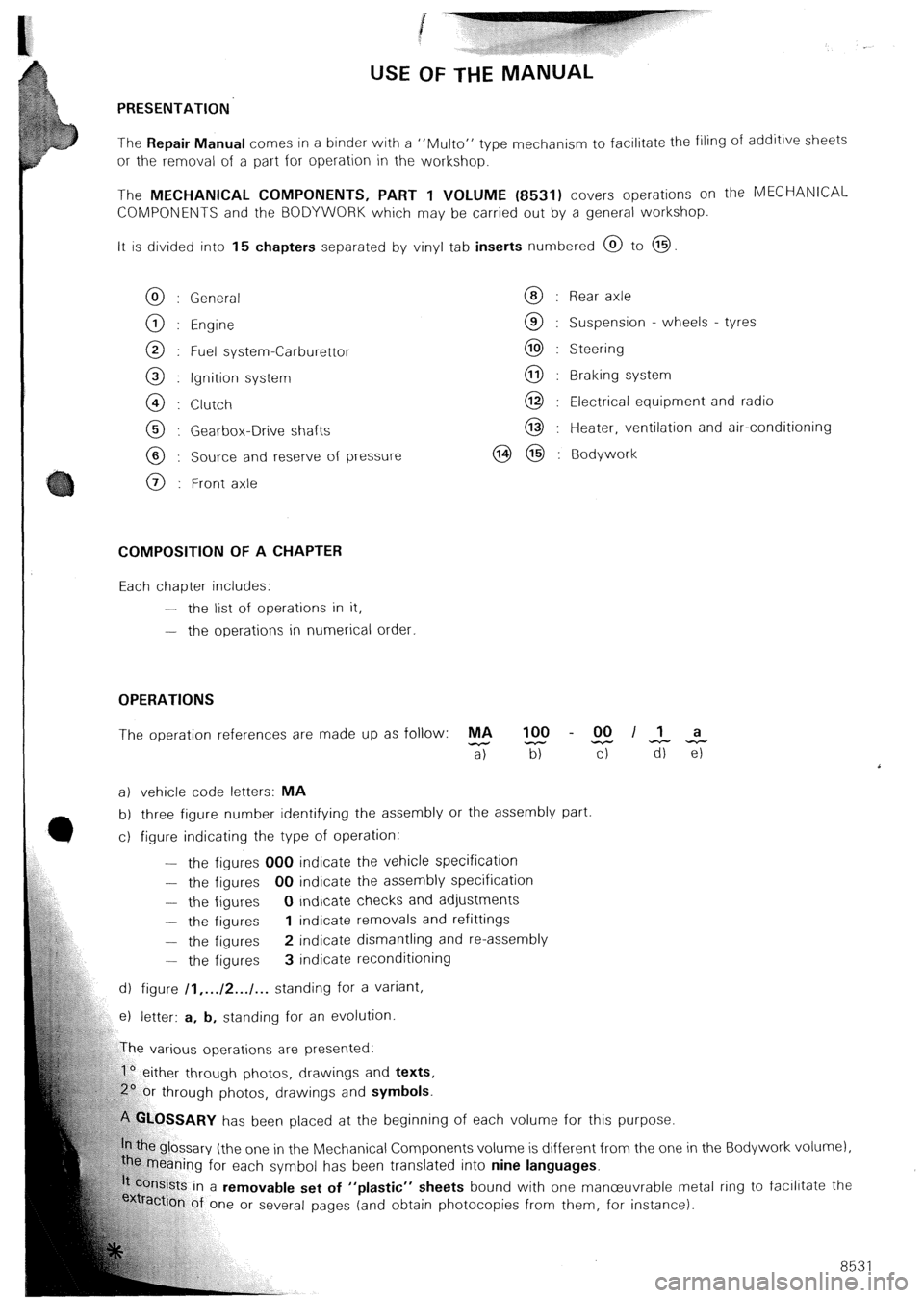
USE OF THE MANUAL
PRESENTATION
The Repair Manual comes in a binder with a “Mu/to” type
mechanism to facilitate the filing of additive sheets
or the removal of a part for operation in the workshop.
The MECHANICAL COMPONENTS, PART 1 VOLUME (8531) covers operations on the MECHANlCAL
COMPONENTS and the BODYWORK which may be carried out by a general workshop.
It is divided into 15 chapters separated by vinyl tab inserts numbered @ to @
General
Engine
Fuel system-Carburettor
Ignition system
Clutch
Gearbox-Drive shafts
Source and reserve of pressure
Front axle Rear axle
Suspension - wheels - tyres
Steering
Braking system
Electrical equipment and radio
Heater, ventilation and air-conditioning
Bodywork
COMPOSITION OF A CHAPTER
Each chapter includes:
-
the list of operations in it,
-
the operations in numerical order.
OPERATIONS
The operation references are made up as follow: MA 100 - 00 II a
-
a) z T-r TiiTz
a) vehicle code letters: MA
b) three figure number identifying the assembly or the assembly part
c) figure indicating the type of operation:
-
the figures 000 indicate the vehicle specification
- the figures 00 indicate the assembly specification
- the figures 0 indicate checks and adjustments
- the figures 1 indicate removals and refittings
- the figures 2 indicate dismantling and re-assembly
-
the figures 3 indicate reconditioning
d) figure /I,... /2.../... standing for a variant,
e) letter: a, b, standing for an evolution
rious operations are presented:
1’ either through photos, drawings and texts,
hrough photos, drawings and symbols.
‘!%.OSSARY has been placed at the beginning of each volume for this purpose.
e glossary (the one in the Mechanical Components volume is different from the one in
caning for each symbol has been translated into nine languages.
kts in a removable set of “plastic” sheets bound with one manceuvrable me
ion of one or several pages (and obtain photocopies from them, for instance). the Bodywork volur nel,
‘tal r ing to facilitate the
85 31
Page 160 of 648
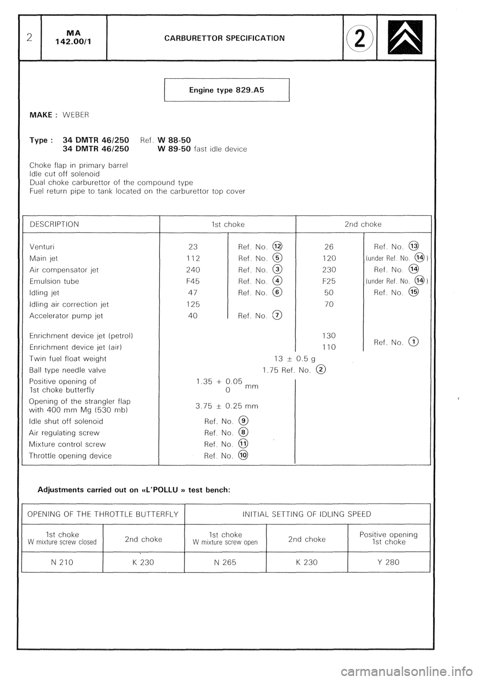
CARBURETTOR SPECIFICATION
Engine type 829.A5
t
MAKE : WEBER
Type : 34 DMTR 461250 Ref. W 88-50
34 DMTR 46/250 W 89-50 fast idle device
Choke flap in primary barrel
Idle cut off solenoid
Dual choke carburettor of the compound type
Fuel return pipe to tank located on the carburettor top cover
DESCRIPTION 1st choke 2nd choke
Venturi
23 Ref. No. @ 26 Ref. No. @
Main jet 112 Ref. No. @ 120 (under Ref No. @)
Air compensator jet
240 Ref. No. @ 230 Ref. No. @
Emulsion tube F45 Ref. No. @ F25 (under Ref. No. @)
Idling jet 47 Ref. No. @ 50 Ref. No. @
Idling air correction jet
125 70
Accelerator pump jet 40 Ref. No. @
Enrichment device jet (petrol) 130
Enrichment device jet (air) 110 Ref. No. @
Twin fuel float weight 13 -t 0.5 g
Ball type needle valve 1.75 Ref. No. @
Positive opening of 1.35 + 0.05 mm
1st choke butterfly 0
Opening of the strangler flap
with 400 mm Mg (530 nib) 3.75 f 0.25 mm
Idle shut off solenoid Ref. No. @
Air regulating screw Ref. No. @
Mixture control screw Ref. No. @
Throttle opening device Ref. No. @
Adjustments carried out on CCL’POLLU v test bench:
OPENING OF THE THROTTLE BUTTERFLY INITIAL SETTING OF IDLING SPEED
1st choke
2nd choke 1st choke Positive opening
W mrxture screw closed W mixture screw open 2nd choke
1st choke
N 210 K 230 N 265 K 230 Y 280
Page 163 of 648
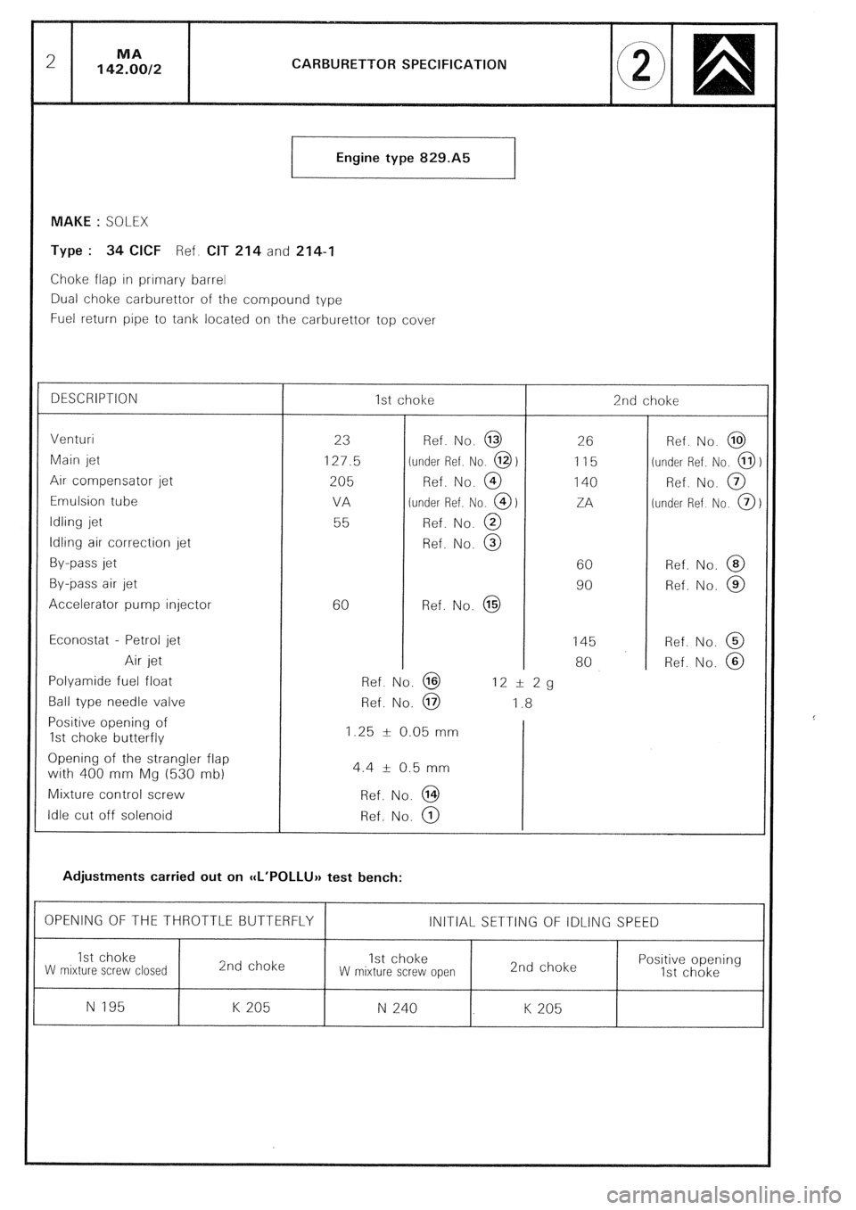
CARBURETTOR SPECIFICATION
Engine type 829.A5
MAKE : SOLEX
Type : 34 CICF Ref. CIT 214 and 214-I
Choke flap in primary barrel
Dual choke carburettor of the compound type
Fuel return pipe to tank located on the carburettor top cover
DESCRIPTION
Venturi
Main jet
Air compensator jet
Emulsion tube
Idling jet
Idling air correction jet
By-pass jet
By-pass air jet
Accelerator pump injector
Econostat - Petrol jet
Air jet
Polyamide fuel float
Ball type needle valve
Positive opening of
1st choke butterfly
Opening of the strangler flap
with 400 mm Mg (530 mb)
Mixture control screw
Idle cut off solenoid 1st choke
23
127.5
205
VA
55
60 Ref. No. @
(under Ref. No. 0)
Ref. No. @
(under Ref. No. @)
Ref. No. @
Ref. No. @
Ref. No. @ 26
115
140
ZA
60
90
145
80 2nd choke
Ref. No. @ 12 I!I 2g
Ref. No. @ 1.8
1.25 k 0.05 mm
4.4 + 0.5 mm
Ref. No. @
Ref. No. @
Adjustments carried out on CCL’POLLUH test bench: Ref. No. @
(under Ref. No. 0
Ref. No. @
[under Ref No. @
Ref. No. @
Ref. No. @
Ref. No. @
Ref. No. @
OPENING OF THE THROTTLE BUTTERFLY 1 INITIAL SETTING OF IDLING SPEED
I
1st choke
W mixture screw closed 2nd choke 1st choke
W mixture screw open 2nd choke
I
Positive opening
1st choke
N 195 K 205 N 240 K 205
Page 166 of 648
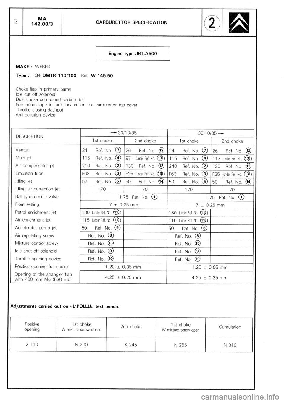
CARBURETTOR SPECIFICATION
Engine type J6T.A500
MAKE : WEBER
Type : 34 DMTR 11 O/100 Ref. W 14550
Choke flap in primary barrel
Idle cut off solenoid
Dual choke compound carburettor
Fuel return pipe to tank located on the carburettor top cover
Throttle closing dashpot
Anti-pollution device
DESCRIPTION - 30110185
30110185 -
1st choke 2nd choke
1st choke 2nd choke
Venturi 24
Ref. No. @ 26 Ref. No. @ 24 Ref. No. @ 26 Ref. No. @
Main jet
1 15 Ref. No. @ 97 (under Ref. No @ 1 11 5 Ref. No. @ 1 17 lunder Ref. No. @ 1
Arr compensator jet
210 Ref. No. @ 130 Ref. No. @ 240 Ref. No. @ 130 Ref. No. @
Emulsion tube
F63 Ref. No. @ F25 iunder Ref No. 0) F63 Ref. No. @ F25 [under Ref. No, 0)
Idling jet 52
Ref. No. @ 50 Ref. No. @ 50 Ref. No. @ 50 Ref. No. @
Idling air correction jet
170 70
170 70
Ball type needle valve
1.75 Ref. No. @ 1.75 Ref. No. @
Float setting
7 i 0.25 mm
7 AI 0.25 mm
Petrol enrichment jet 130 (under Ref No. @ )
130 lunder Ref. No @ 1
Air enrichment jet
1 15 [under Ref No. 0) 1 1 5 [under Ref. No. @ 1
Accelerator pump jet 50
Ref. No. @ 50 Ref. No. @
Air regulating screw
Ref. No. @ Ref. No. @
Mixture control screw Ref. No. @
Ref. No. @
Idle shut off solenoid
Ref. No. @ Ref. No. @
Throttle opening device Ref. No. @
Ref. No. @
Positive opening full choke
1.20 i 0.05 mm 1.20 -fr 0.05 mm
Opening of the strangler flap
with 400 mm Mg (530 mb) 4.25 + 0.25 mm
4.25 --lr 0.25 mm
djustments carried out on ccL’POLLU>) test bench:
Positive
1st choke
2nd choke 1st choke
opening
W mrxture screw closed
W mixture screw open Cumulation
x 110
N 200 K 245 N 255
N 310
Page 169 of 648
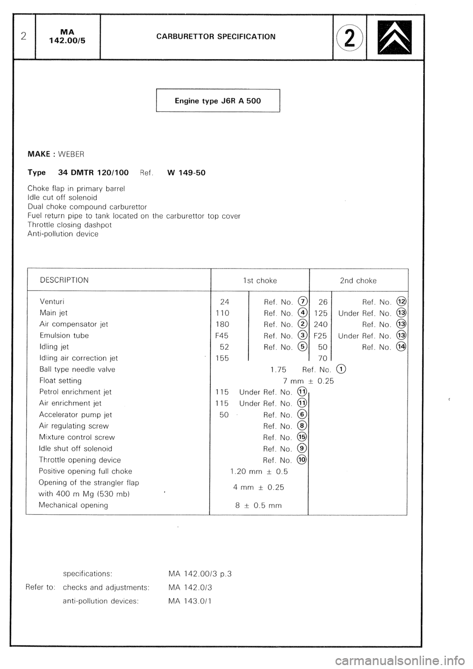
CARBURETTOR SPECIFICATION
Engine type J6R A 500
1 MAKE : WEBER
Type 34 DMTR 120/100 Ref. w 149-50
Choke flap in primary barrel
Idle cut off solenoid
Dual choke compound carburettor
Fuel return pipe to tank located on the carburettor top cover
Throttle closing dashpot
Anti-oollution device
DESCRIPTION 1st choke 2nd choke
Venturi
Main jet
Air compensator jet
Emulsion tube
Idling jet
Idling air correction jet
Ball type needle valve
Float setting
Petrol enrichment jet
Air enrichment jet
Accelerator pump jet
Air regulating screw
Mixture control screw
Idle shut off solenoid
Throttle opening device
Positive opening full choke
Opening of the strangler flap
with 400 m Mg (530 mb)
Mechanical opening 24 Ref. No. @ 26 Ref. No. @
110 Ref. No. @ 125 Under Ref. No. @
180 Ref. No. @ 240 Ref. No. @
F45 Ref. No. @ F25 Under Ref. No. @
52 Ref. No. @ 50 Ref. No. @
155 70
1.75 Ref. No. @)
7 mm & 0.25
115 Under Ref. No. @
115 Under Ref. No. @
50 Ref. No. @
Ref. No. @
Ref. No. @
Ref. No. @
Ref. No. @
1.20 mm f 0.5
4 mm f 0.25
8 t- 0.5 mm
specifications: MA 142.0013 p.3
Refer to: checks and adjustments: MA 142.013
anti-pollution devices: MA 143.011
Page 212 of 648
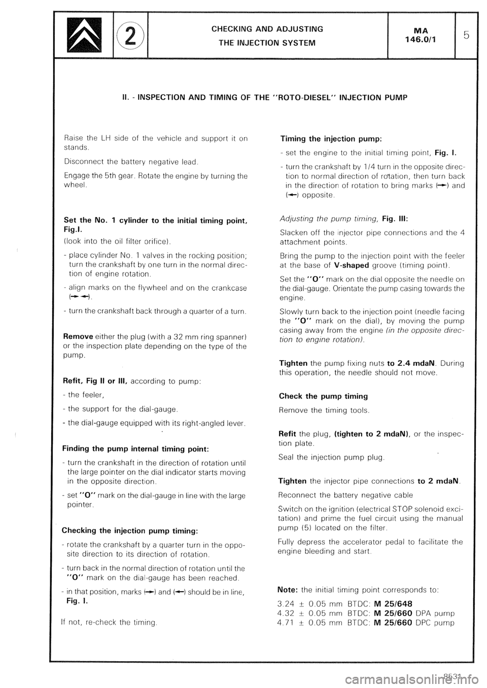
CHECKING AND ADJUSTING
THE INJECTION SYSTEM
II. - INSPECTION AND TIMING OF THE “ROT0-DIESEL” INJECTION PUMP
Raise the LH side of the vehicle and support it on
stands.
Disconnect the battery negative lead.
Engage the 5th gear. Rotate the engine by turning the
wheel.
Set the No. 1 cylinder to the initial timing point,
Fig.1.
(look into the oil filter orifice).
- place cylinder No. 1 valves in the rocking position;
turn the crankshaft by one turn in the normal direc-
tion of engine rotation.
- align marks on the flywheel and on the crankcase
(++I.
- turn the crankshaft back through a quarter of a turn.
Remove either the plug (with a 32 mm ring spanner)
or the inspection plate depending on the type of the
pump.
Refit, Fig II or Ill, according to pump:
- the feeler,
- the support for the dial-gauge.
- the dial-gauge equipped with its right-angled lever.
Finding the pump internal timing point:
- turn the crankshaft in the direction of rotation until
the large pointer on the dial indicator starts moving
in the opposite direction.
- set “0” mark on the dial-gauge in line with the large
pointer.
Checking the injection pump timing:
- rotate the crankshaft by a quarter turn in the oppo-
site direction to its direction of rotation.
- turn back in the normal direction of rotation until the
“0” mark on the dial-gauge has been reached.
- in that position, marks (-1 and (c) should be in line,
Fig. I.
If not, re-check the timing. Timing the injection pump:
- set the engine to the initial trming point, Fig. I.
- turn the crankshaft by 114 turn in the opposite direc-
tion to normal direction of ro’tatron, then turn back
in the direction of rotation to bring marks t-+) and
+-I opposite.
Adjusting the pump timing, Fig. Ill:
Slacken off the injector pipe connections and the 4
attachment points.
Bring the pump to the injection point with the feeler
at the base of V-shaped groove (timing point).
Set the “0” mark on the dial opposite the needle on
the dial-gauge. Orientate the pump casing towards the
engine.
Slowly turn back to the injection point (needle facing
the “0” mark on the dial), by moving the pump
casing away from the engine (in the opposite direc-
tion to engine rotation).
Tighten the pump fixing nuts to 2.4 mdaN. During
this operation, the needle should not move.
Check the pump timing
Remove the timing tools.
Refit the plug, (tighten to 2 mdaN), or the inspec-
tion plate.
Seal the injection pump plug.
Tighten the injector pipe connections to 2 mdaN.
Reconnect the battery negative cable
Switch on the ignition (electrical STOP solenoid exci-
tation) and prime the fuel circuit using the manual
pump (5) located on the filter.
Fully depress the accelerator pedal to facilitate the
engine bleeding and start.
Note: the initial timing point corresponds to:
3.24 -L- 0.05 mm BTDC: M 25/648
4.32 + 0.05 mm BTDC: M 25/660 DPA pump
4.71 f 0.05 mm BTDC: M 25/660 DPC pump
8531
Page 224 of 648
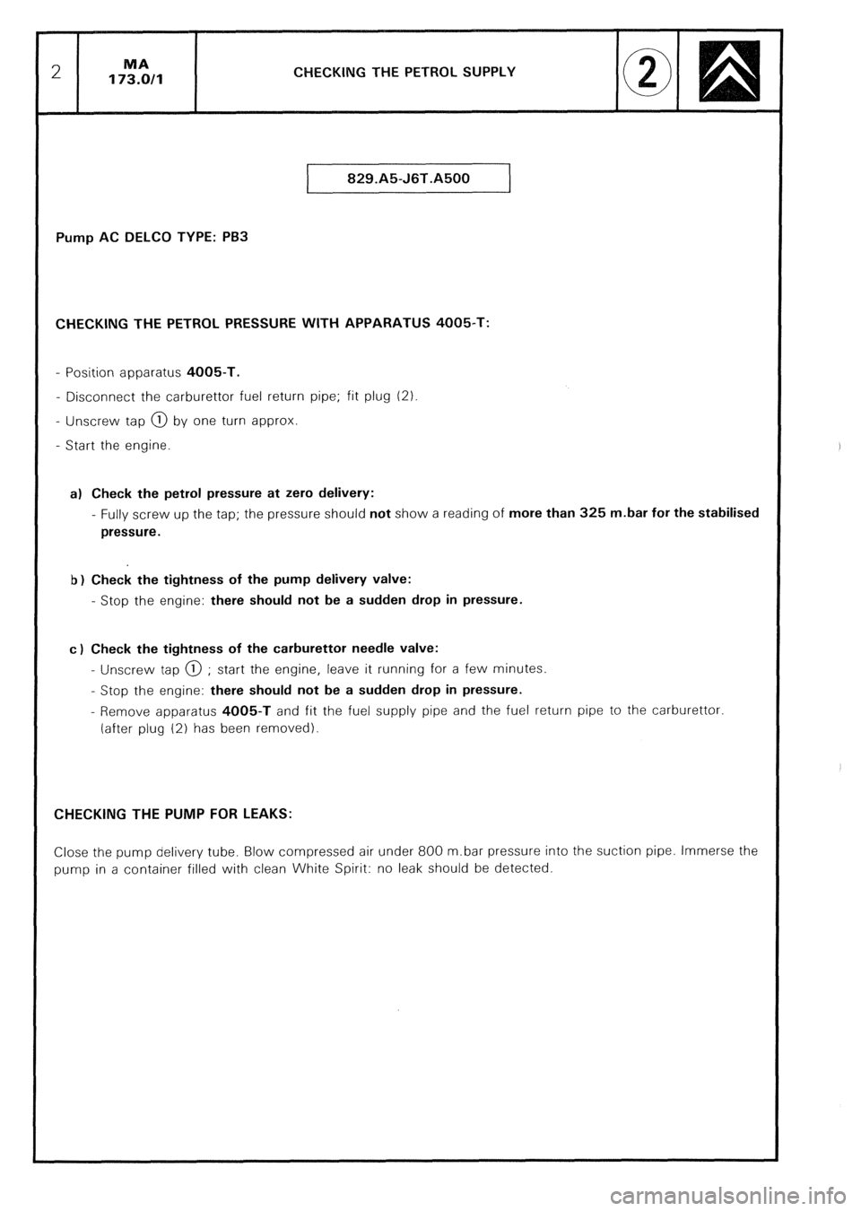
CHECKING THE PETROL SUPPLY
829.A5-J6T.A500
Pump AC DELCO TYPE: PB3
CHECKING THE PETROL PRESSURE WITH APPARATUS 4005-T:
- Position apparatus 4005-T.
- Disconnect the carburettor fuel return pipe; fit plug (2)
- Unscrew tap @ by one turn approx.
- Start the engine.
a) Check the petrol pressure at zero delivery:
- Fully screw up the tap; the pressure should not show a reading of more than 325 m.bar for the stabilised
pressure.
b) Check the tightness of the pump delivery valve:
- Stop the engine: there should not be a sudden drop in pressure.
c) Check the tightness of the carburettor needle valve:
- Unscrew tap @ ; start the engine, leave it running for a few minutes.
- Stop the engine: there should not be a sudden drop in pressure.
- Remove apparatus 4005-T and fit the fuel supply pipe and the fuel return pipe to the carburettor
(after plug (2) has been removed).
CHECKING THE PUMP FOR LEAKS:
Close the pump delivery tube. Blow compressed air under 800 m.bar pressure into the suction pipe. Immerse the
pump in a container filled with clean White Spirit: no leak should be detected.
Page 260 of 648
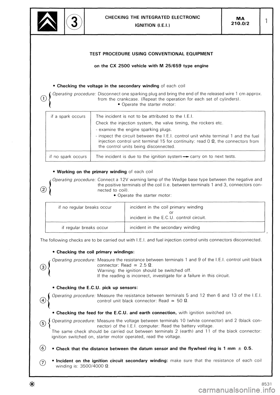
CHECKING THE INTEGRATED ELECTRONlC
IGNITION (I.E.I.)
TEST PROCEDURE USING CONVENTIONAL EQUIPMENT
on the CX 2500 vehicle with M 25/659 type engine
l Checking the voltage in the secondary winding of each coil
0 Operating procedure: Disconnect one sparking plug and bring the end of the released wire 1 cm approx
from the crankcase. (Repeat the operation for each set of cylinders).
l Operate the starter motor:
if a spark occurs The incident is not to be attributed to the I.E.I.
Check the injection system, the valve timing, the rockers etc.
- examine the engine sparking plugs.
- inspect the circuit between the I.E.I. control unit white terminal 1 and the fuel
injection control unit terminal 15 for continuity: read 0 0, the connectors from
the control units being disconnected.
if no spark occurs The incident is due to the ignition system--ccarry on to next tests.
l Working on the primary winding of each coil
Operating procedure: Connect a 12V warning lamp of the Wedge base type between the negative and
0 the positive terminals of the coil (i.e. between terminals 1 and 3, connectors con-
netted to coil).
l Operate the starter motor:
if no regular breaks occur incident in the coil primary winding
or
incident in the E.C.U. control circuit.
if regular breaks occur incident in the secondary winding
The following checks are to be carried out with I.E.I. and fuel injection control units connectors disconnected.
l Checking the coil primary windings:
Operating procedure: Measure the resistance between terminals 1 and 9 of the I.E.I. control unit black
0 connector: Read = 2.5 0.
Warning: the ignition should be switched off.
If the reading is incorrect, investigate for a failure in this circuit.
l Checking the E.C.U. pick up sensors:
co Operating procedure: Measure the resistance between terminals 5 and 12 then 6 and 13 of the I.E.I.
control unit black connector: Read = 50 a.
l Checking the feed for the E.C.U. and earth connection, with ignition switched on
Operating procedure: Measure the voltage between terminals IO (white connector) and 2 (black con-
nector) of the I.E.I. computer: Read the battery voltage.
The same check should be carried out between terminals 2 (earth) and 11 of the black connector:
ignition switched on, starter motor operated, read the voltage.
69 l Check that the distance between the datum sensor and the flywheel ring is 1 mm + 0.5.
0 l Incident on the ignition circuit secondary winding: make sure that the resistance of each coil
winding is: 350014000 a.
8531
Page 261 of 648
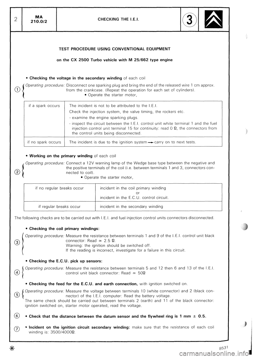
CHECKING THE I.E.I.
TEST PROCEDURE USING CONVENTIONAL EQUIPMENT
on the CX 2500 Turbo vehicle with M 25/662 type engine
0 Checking the voltage in the secondary winding of each coil
0 Operating procedure: Disconnect one sparking plug and bring the end of the released wire 1 cm approx
from the crankcase. (Repeat the operation for each set of cylinders).
0 Operate the starter motor,
if a spark occurs
if no spark occurs The incident is not to be attributed to the I.E.I.
Check the injection system, the valve timing, the rockers etc.
- examine the engine sparking plugs.
- inspect the circuit between the I.E.I. control unit white terminal 1 and the fuel
injection control unit terminal 15 for continuity: read 0 Q, the connectors from
the control units being disconnected.
The incident is due to the ignition system-carry on to next tests.
l Working on the primary winding of each coil
Operating procedure: Connect a 12V warning lamp of the Wedge base type between the negative and
the positive terminals of the coil (i.e. between terminals 1 and 3, connectors con-
netted to coil).
l Operate the starter motor,
if no regular breaks occur incident in the coil primary winding
or
incident in the E.C.U. control circuit.
if regular breaks occur incident in the secondary winding
The following checks are to be carried out with I.E.I. and fuel injection control units connectors disconnected.
0 Checking the coil primary windings:
Operating procedure: Measure the resistance between terminals 1 and 9 of the I.E.I. control unit black
0 connector: Read = 2.5 Q.
Warning: the ignition should be switched off.
If the reading is incorrect, investigate for a failure in this circuit.
l Checking the E.C.U. pick up sensors:
OI Operating procedure: Measure the resistance between terminals 5 and 12 then 6 and 13 of the I.E.I.
4
control unit black connector: Read 2: 5OQ
0 Checking the feed for the E.C.U. and earth connection, with ignition switched on.
d 5 Operating procedure: Measure the voltage between terminals 10 (white connector) and 2 (black con-
nectar) of the I.E.I. computer: Read the battery voltage.
The same check should be carried out between terminals 2 (earth) and 11 of the black connector:
ignition switched on, starter motor operated, read the voltage.
@ 0 Check that the distance between the datum sensor and the flywheel ring is 1 mm + 0.5.
0 * Incident on the ignition circuit secondary winding: make sure that the resistance of each coil
winding is: 350014OOOQ.