lock CITROEN DISPATCH SPACETOURER 2018 Handbook (in English)
[x] Cancel search | Manufacturer: CITROEN, Model Year: 2018, Model line: DISPATCH SPACETOURER, Model: CITROEN DISPATCH SPACETOURER 2018Pages: 400, PDF Size: 16.99 MB
Page 78 of 400

76
Steering wheel adjustment
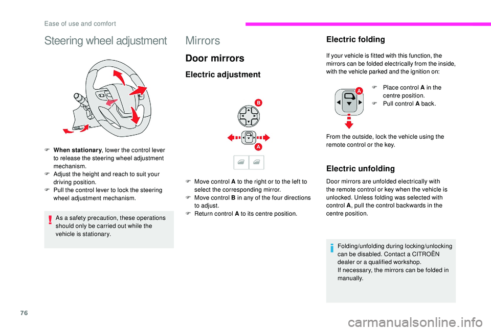
F When stationary, lower the control lever
to release the steering wheel adjustment
mechanism.
F
A
djust the height and reach to suit your
driving position.
F
P
ull the control lever to lock the steering
wheel adjustment mechanism.
As a safety precaution, these operations
should only be carried out while the
vehicle is stationary.
Mirrors
Door mirrors
Electric adjustment
F Move control A to the right or to the left to select the corresponding mirror.
F
M
ove control B in any of the four directions
to adjust.
F
R
eturn control A to its centre position.
Electric folding
If your vehicle is fitted with this function, the
mirrors can be folded electrically from the inside,
with the vehicle parked and the ignition on:
Electric unfolding
Door mirrors are unfolded electrically with
the remote control or key when the vehicle is
unlocked. Unless folding was selected with
control A , pull the control backwards in the
centre position.
Folding/unfolding during locking/unlocking
can be disabled. Contact a CITROËN
dealer or a qualified workshop.
If necessary, the mirrors can be folded in
manually. F
P
lace control A in the
centre position.
F
P
ull control A back.
From the outside, lock the vehicle using the
remote control or the key.
Ease of use and comfort
Page 88 of 400

86
Angled head restraints
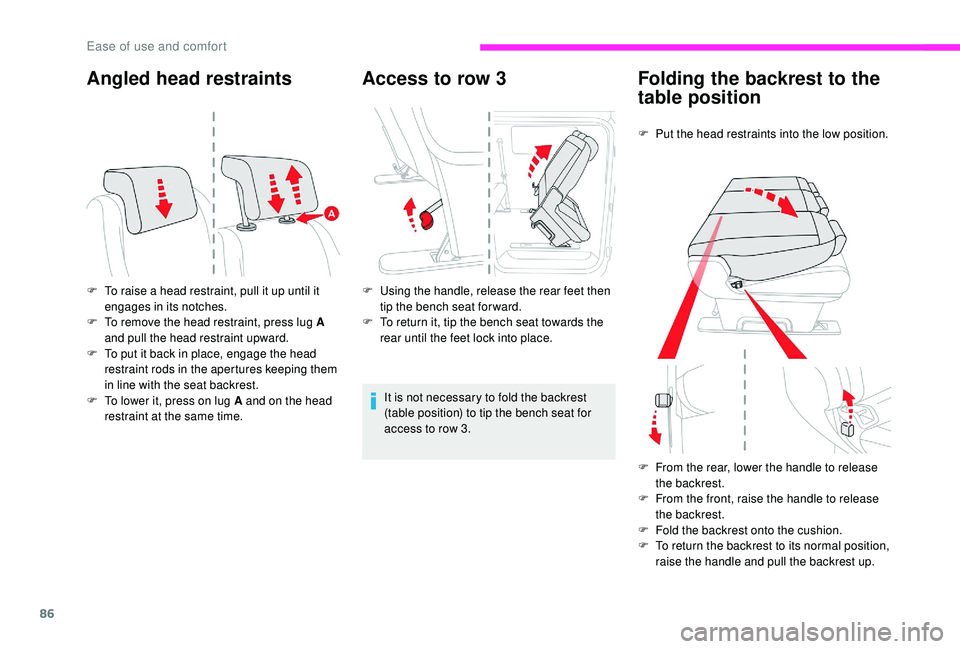
F To raise a head restraint, pull it up until it engages in its notches.
F
T
o remove the head restraint, press lug A
and pull the head restraint upward.
F
T
o put it back in place, engage the head
restraint rods in the apertures keeping them
in line with the seat backrest.
F
T
o lower it, press on lug A and on the head
restraint at the same time.
Access to row 3
F Using the handle, release the rear feet then tip the bench seat for ward.
F
T
o return it, tip the bench seat towards the
rear until the feet lock into place.
It is not necessary to fold the backrest
(table position) to tip the bench seat for
access to row 3.
Folding the backrest to the
table position
F Put the head restraints into the low position.
F
F
rom the rear, lower the handle to release
the backrest.
F
F
rom the front, raise the handle to release
the backrest.
F
F
old the backrest onto the cushion.
F
T
o return the backrest to its normal position,
raise the handle and pull the backrest up.
Ease of use and comfort
Page 89 of 400

87
Do not leave objects (such as a bag or
toys) on the cushion when folding the
backrest.
Tilting
F If your vehicle has the facility, place the backrest in the table position.
F
U
sing the handle, release the rear feet then
tip the seat for ward.
F
T
o return the seat, tip the bench towards the
rear until the feet lock into place.
Removing a seat
F If your vehicle has the facility, place the backrest in the table position.
F
T
ip the bench seat for ward. F
R
elease the front feet using the handles.
F
D
isengage the bench seat from its
anchorages.
F
R
emove the bench seat.
If removing and storing a bench seat out
of the vehicle, ensure that it is placed in a
clean area, so as to avoid introducing any
foreign bodies into the mechanisms.
The bench seat is not designed for any
other purpose than on-board the vehicle.
It has mechanisms and may not operate
correctly if used inappropriately or
dropped.
Refitting
F Check that there is no object obstructing the anchorages and preventing the feet locking
into place.
F
E
ngage the front feet in the anchorages on
the floor (as shown above).
Be aware of the feet of passengers when
refitting a seat.
F
L
ock the front feet using the handles.
F
T
ip the bench seat toward the rear until the
rear feet lock into place.
3
Ease of use and comfort
Page 92 of 400

90
Tilting
(example of an individual seat)
F
I
f your vehicle has the facility, place the
backrest in the table position.
F
U
sing the handle, release the rear feet then
tip the seat for ward.
F
T
o return the seat to the normal position, tip
the seat backwards until it engages in its
anchorages.
Removing a seat
(example of an individual seat)
F
I
f your vehicle has the facility, place the
backrest in the table position.
F
T
ip the seat for ward.
F
R
elease the front feet using the handles.
F
D
isengage the seat from its anchorages.
F
R
emove the seat by the sliding door in
row 2
or from the rear in row 3.
If removing and storing a seat (or bench
seat) out of the vehicle, ensure that it is
placed in a clean area, so as to avoid
introducing any foreign bodies into the
mechanisms. The seat (or bench seat) is not designed
for any other purposes than on-board the
vehicle. It has mechanisms and may be
damaged if used improperly or if dropped.
Refitting
(example of an individual seat)
F
C
heck that there is no object obstructing the
anchorages and preventing the feet locking
into place.
F
E
ngage the front feet in the anchorages on
the floor (as shown above).
Ease of use and comfort
Page 93 of 400

91
F Lock the front feet using the handles.
F T ilt the seat backwards until the rear feet
lock into place.
Be aware of the feet of passengers when
tipping a seat.
Check that the seat has correctly engaged in its
anchorages on the floor when returned to the
seating position. F
I
f fitted to your vehicle, pull the control
to raise the backrest (from the rear,
lower the handle).
Ensure that no object, or the feet of a
passenger seated at the rear, could
obstruct the anchorage points or prevent
the correct latching of the assembly.
Rear seat and bench seat
on rails
The different levels of equipment and settings
described hereafter vary according to the
version and the configuration of your vehicle.
The individual seat is always on the right and
the bench seat on the left (facing for ward).
The bench seat has two independent
backrests.
3
Ease of use and comfort
Page 105 of 400

103
On the passenger side, do not forget to
fold the "aircraft" type table before placing
the seat in the table position.
Do not place hard or heavy objects on
the table. They could become dangerous
projectiles in the event of emergency
braking or impact.
For more information on the Front seats
and, in particular, the "table" position for
the backrest, refer to the corresponding
section.
12 V accessory socket(s)
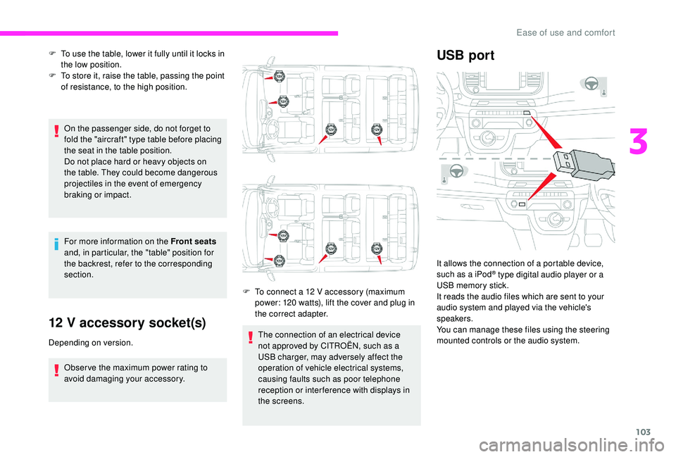
Depending on version.
Obser ve the maximum power rating to
avoid damaging your accessory. F
T
o connect a 12 V accessory (maximum
power: 120 watts), lift the cover and plug in
the correct adapter.
F
T
o use the table, lower it fully until it locks in
the low position.
F
T
o store it, raise the table, passing the point
of resistance, to the high position.
The connection of an electrical device
not approved by CITROËN, such as a
USB charger, may adversely affect the
operation of vehicle electrical systems,
causing faults such as poor telephone
reception or inter ference with displays in
the screens.
USB port
It allows the connection of a portable device,
such as a iPod® type digital audio player or a
USB memory stick.
It reads the audio files which are sent to your
audio system and played via the vehicle's
speakers.
You can manage these files using the steering
mounted controls or the audio system.
3
Ease of use and comfort
Page 109 of 400

107
Lower fixings (behind row 2)
Fitting the net
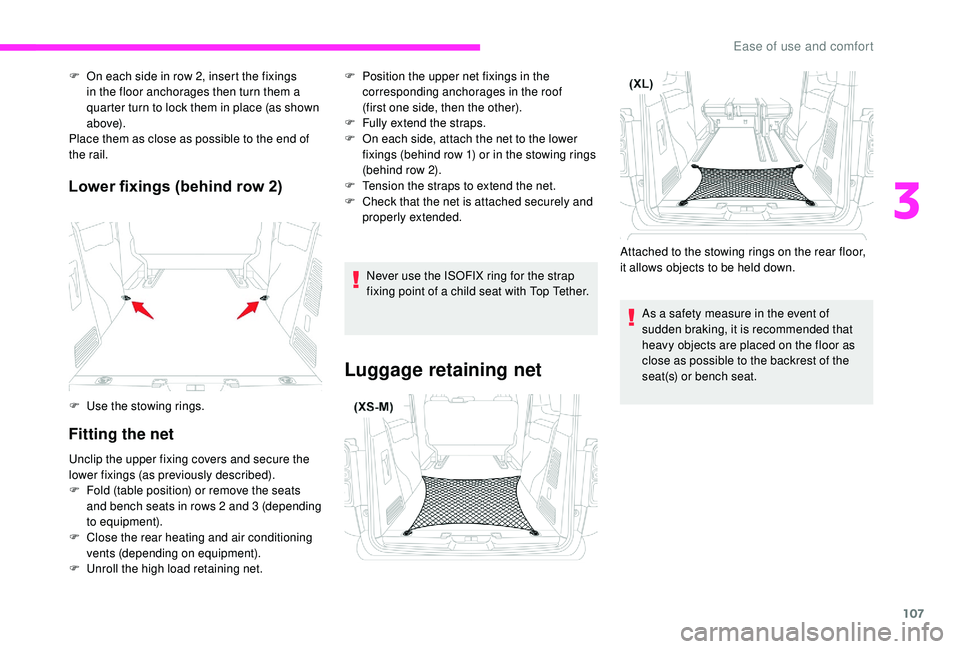
F On each side in row 2, insert the fixings in the floor anchorages then turn them a
quarter turn to lock them in place (as shown
a b ove).
Place them as close as possible to the end of
the rail.
F
U
se the stowing rings.
Unclip the upper fixing covers and secure the
lower fixings (as previously described).
F
F
old (table position) or remove the seats
and bench seats in rows 2
and 3 (depending
to equipment).
F
C
lose the rear heating and air conditioning
vents (depending on equipment).
F
U
nroll the high load retaining net. F
P osition the upper net fixings in the
corresponding anchorages in the roof
(first one side, then the other).
F
F
ully extend the straps.
F
O
n each side, attach the net to the lower
fixings (behind row 1) or in the stowing rings
(behind row 2).
F
T
ension the straps to extend the net.
F
C
heck that the net is attached securely and
properly extended.
Never use the ISOFIX ring for the strap
fixing point of a child seat with Top Tether.
Luggage retaining net
Attached to the stowing rings on the rear floor,
it allows objects to be held down. As a safety measure in the event of
sudden braking, it is recommended that
heavy objects are placed on the floor as
close as possible to the backrest of the
seat(s) or bench seat.
3
Ease of use and comfort
Page 110 of 400

108
Windows in row 2
If fitted to your vehicle, the side windows in
row 2 can be opened.
For more information on the Child lock on
rear windows , refer to the corresponding
section.
While driving, the window must be closed or
secured at one of the notches.
F
S
queeze the two controls then move the
window sideways.
Side blinds
Fitted to the windows in the second row, they
protect the passenger compartment from the
sun's rays.
F
P
ull the tab A and anchor the blind on the
hook B .
Always guide the blind slowly using the
tab, both up and down.
Load space cover
F Raise it to remove it.
F T o install it, insert the guides into their
housings.
When sharp deceleration occurs, objects
placed on the luggage cover can turn into
projectiles.
Ease of use and comfort
Page 113 of 400

111
F Lift the control (without going beyond the point of resistance) and slide the assembly
forwards or backwards.
F
R
elease the control when it is in the desired
position.
F
C
heck that the table is secured on the
runner. If this is not the case, move the
assembly slightly to the next notch on the
r u n n e r.
You can move the table in both the open
and stowed position. However, to ensure
safety, it is advised that you handle the
assembly in the stowed position.
To ensure that the table runs smoothly,
ensure that no objects are blocking the
space used by the runner on the floor.
Before manoeuvring the table, check that
there is nothing on the table.Unfolding
F Operate the control on the top and pull the table assembly up until it clicks into place.
F
P
ull each table top fully up then pivot them
on each side into the horizontal position.
Folding
F Raise each table top, going beyond the point of resistance, to the vertical position.
F
P
ush each table top down into its housing
until it clicks into place.
F
P
ush the control then tip the table assembly
downward until it clicks into place.
Before stowing the table tops, check that
they are clear. Before tipping the assembly
down, check that the two table tops have
clicked home in the low position and that
there is nothing in the cup holder area
(such as a can or pen).
3
Ease of use and comfort
Page 115 of 400

113
Refitting
F Check that there is no object obstructing the runner and preventing locking.
F
C
heck that the control is in the high position
(locking mechanism engaged). Otherwise,
lift the control as far as it can go to engage
the mechanism.
F
P
lace the front of the table on the runner.
F
T
aking care not to inter fere with the control,
tip the assembly down at the rear until it
clicks into place.
F
C
heck that the assembly is locked in the
runner. If this is not the case, move the
assembly slightly to the next notch on the
r u n n e r. Other wise there is a risk of injury in the
event of an accident or sudden braking.
F
R
elease the control until the guide latches
in the runner.
Be careful of passengers' feet when
manoeuvring the assembly.
Storage off the runner
If removing and storing the table out of
the vehicle, ensure that it is placed in a
clean area, so as to avoid introducing any
foreign bodies into the mechanisms.
The table must be placed outside the
vehicle, on a flat and level sur face, resting
against the guide so as not to damage
visible parts. Caution, when out of the vehicle, the table
leans to the right or left when put down.
3
Ease of use and comfort