ESP Citroen DS3 2009.5 1.G Owner's Guide
[x] Cancel search | Manufacturer: CITROEN, Model Year: 2009.5, Model line: DS3, Model: Citroen DS3 2009.5 1.GPages: 248, PDF Size: 7.09 MB
Page 142 of 248
Gear change indicator *
Operation
The system inter venes only when driving economically.
Depending on the driving situation and your vehicle's equipment, the system may advise you to skip one or more gears. You can follow this instruction without engaging the intermediate gears. The gear engagement recommendations must not be considered compulsory. In fact, the configuration of the road, the amount of traffic and safety remain determining factors when choosing the best gear. Therefore, the driver remains responsible for deciding whether or not to follow the advice given by the system. This function cannot be deactivated.
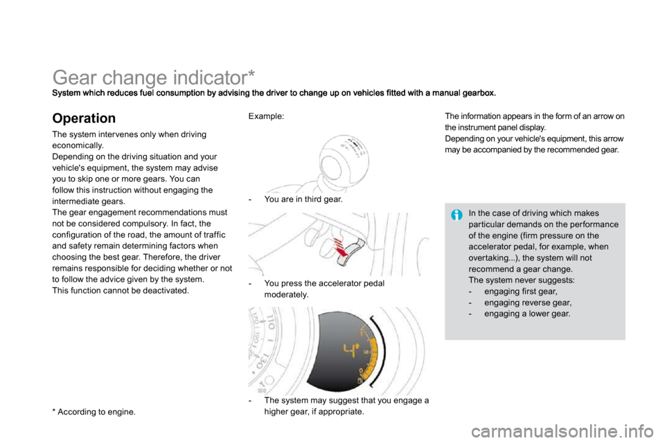
- The system may suggest that you engage a higher gear, if appropriate.
The information appears in the form of an arrow on the instrument panel display. Depending on your vehicle's equipment, this arrow may be accompanied by the recommended gear.
In the case of driving which makes par ticular demands on the per formance of the engine (firm pressure on the accelerator pedal, for example, when over taking...), the system will not recommend a gear change. The system never suggests: - engaging first gear, - engaging reverse gear, - engaging a lower gear.
* According to engine.
Example:
- You are in third gear.
- You press the accelerator pedal moderately.
Page 144 of 248
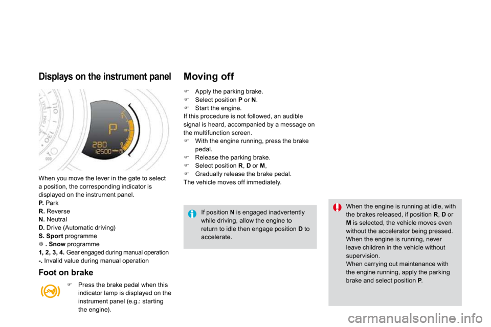
When you move the lever in the gate to select a position, the corresponding indicator is displayed on the instrument panel. P. Park R. Reverse N. Neutral D. Drive (Automatic driving) S. Spor t programme � . Snow programme 1, 2, 3, 4. Gear engaged during manual operation -. Invalid value during manual operation
Displays on the instrument panel
Foot on brake
� Press the brake pedal when this indicator lamp is displayed on the instrument panel (e.g.: star ting the engine).
Moving off
If position N is engaged inadver tently while driving, allow the engine to return to idle then engage position D to accelerate.
When the engine is running at idle, with the brakes released, if position R , D or
M is selected, the vehicle moves even without the accelerator being pressed. When the engine is running, never leave children in the vehicle without super vision. When carrying out maintenance with the engine running, apply the parking brake and select position P . PP
� Apply the parking brake. � Select position P or N . � Star t the engine. If this procedure is not followed, an audible signal is heard, accompanied by a message on the multifunction screen. � With the engine running, press the brake pedal. � Release the parking brake. � Select position R , D or M , � Gradually release the brake pedal. The vehicle moves off immediately.
Page 147 of 248
155Driving
System which prevents the vehicle from exceeding the speed programmed by the driver. When the programmed speed limit is reached, pressing the accelerator pedal in the normal manner no longer has any effect. The speed limiter is switched on manually: it requires a programmed speed of at least 20 mph (30 km/h). The speed limiter is switched off by manual d offoperation of the control. The programmed speed can be exceeded temporarily by pressing the accelerator firmly. To return to the programmed speed, simply slow down to a speed below the programmed speed. The programmed speed remains in the memory when the ignition is switched off.
Speed limiter
The speed limiter cannot, in any circumstances, replace the need to respect speed limits, nor can it replace the need for vigilance and responsibility on the par t of the driver.
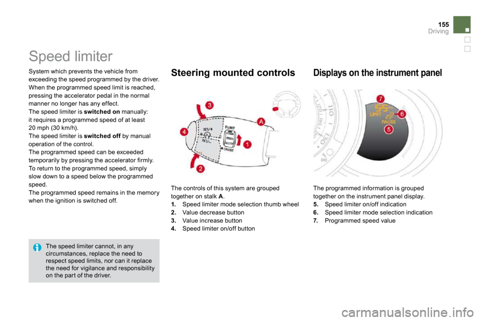
The controls of this system are grouped together on stalk A . 1. Speed limiter mode selection thumb wheel 2. Value decrease button 3. Value increase button 4. Speed limiter on/off button
Steering mounted controls
The programmed information is grouped together on the instrument panel display. 5. Speed limiter on/off indication 6. Speed limiter mode selection indication 7. Programmed speed value
Displays on the instrument panel
Page 149 of 248
157Driving
Cruise control
System which automatically maintains the speed of the vehicle at the value programmed by the driver, without any action on the accelerator pedal. The cruise control is switched on manually: it requires a minimum vehicle speed of 25 mph (40 km/h), as well as the engagement of: - four th gear on a manual gearbox, - second gear on an automatic gearbox, in sequential mode, - position D on an automatic gearbox. The cruise control is switched off manually d offor by pressing the brake or clutch pedal or on triggering of the ESP system for safety reasons. It is possible to exceed the programmed speed temporarily by pressing the accelerator pedal. To return to the programmed speed, simply release the accelerator pedal. Switching off the ignition cancels any programmed speed value.
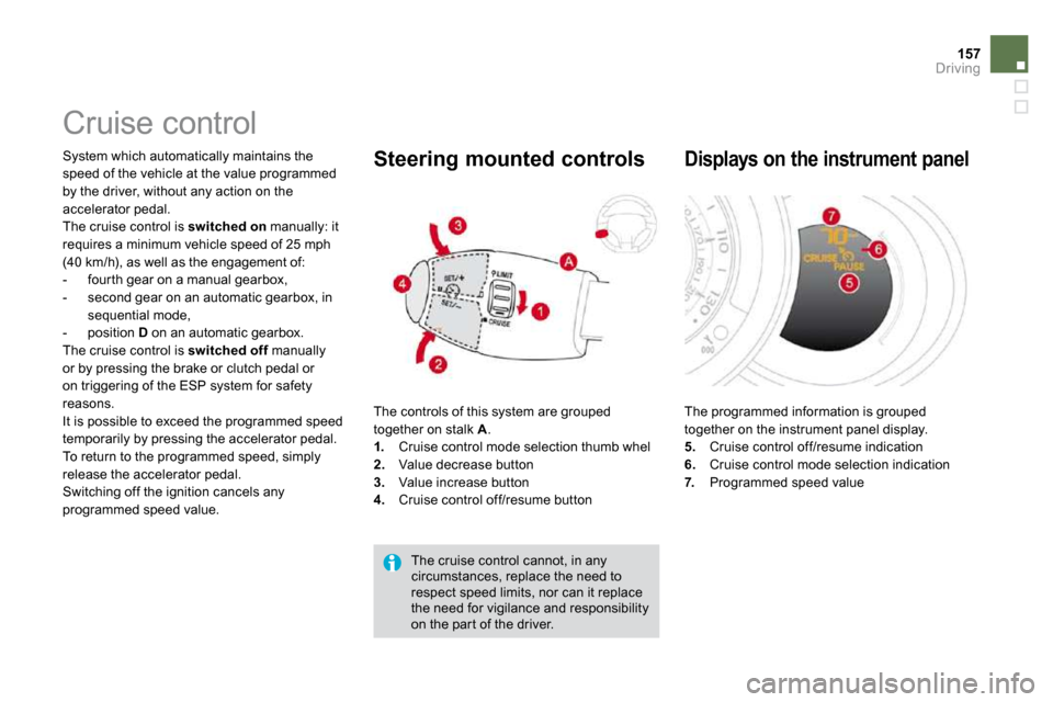
The controls of this system are grouped together on stalk A . 1. Cruise control mode selection thumb whel 2. Value decrease button 3. Value increase button 4. Cruise control off/resume button
Steering mounted controls
The cruise control cannot, in any circumstances, replace the need to respect speed limits, nor can it replace the need for vigilance and responsibility on the par t of the driver.
The programmed information is grouped together on the instrument panel display. 5. Cruise control off/resume indication 6. Cruise control mode selection indication 7. Programmed speed value
Displays on the instrument panel
Page 151 of 248

159Driving
Rear parking sensors
System consisting of four proximity sensors, located in the rear bumper. This detects any obstacle (person, vehicle, tree, gate, etc.) behind the vehicle, except obstacles located just below the bumper.
An object, such as a stake, a roadworks cone or any other similar object may be detected at the beginning of the manoeuvre, but may no longer be detected when the vehicle comes close to it.
The parking sensor system cannot, in any circumstances, take the place of the vigilance and responsibility of the driver.
The system is activated as soon as reverse gear is engaged, accompanied by an audible signal. The proximity information is given by: - an audible signal, which becomes more
rapid as the vehicle approaches the obstacle. - a graphic on the multifunction screen, with
blocks which become increasingly closer to the vehicle.
Activation
When the distance between the rear of the vehicle and the obstacle is less than thirty centimetres, t he audible signal becomes continuous and the "Danger" symbol appears on the multifunction screen. On completion of the manoeuvre, when you exit reverse gear, the system becomes inactive.
Page 152 of 248

Programming Operating faults
If there is an operating fault, when reverse gear is engaged this warning lamp comes on on the instrument panel, accompanied by an audible signal (shor t beep) and a message on the multifunction screen.
You can activate or deactivate the system by means of the multifunction screen configuration menu. The system state is memorised when switching off the ignition. For more information on access to the parking assistance menu, refer to vehicle configuration in the "Multifunction screens" section corresponding to your screen.
The system will be deactivated automatically when towing a trailer or when a bicycle carrier is fitted (vehicle fitted with a towbar or bicycle carrier recommended by CITROËN).
In bad or wintry weather, ensure that the sensors are not covered with mud, frost or snow.
Page 158 of 248
169Checks
Checking levels
Check all of these levels regularly and top them up if necessary, unless other wise indicated. If a level drops significantly, have the corresponding system checked by a CITROËN dealer.
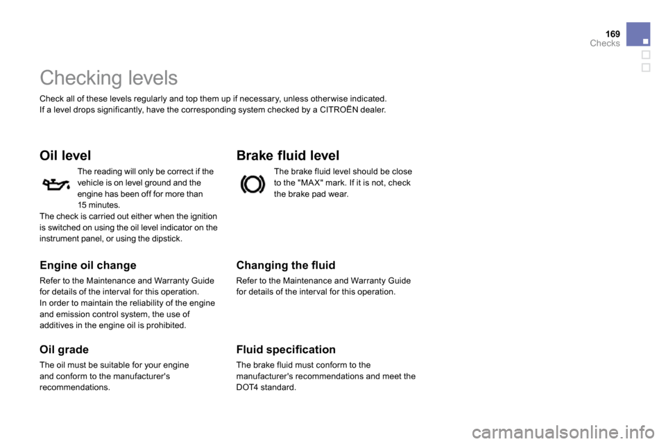
Oil level
Engine oil change
Refer to the Maintenance and Warranty Guide for details of the inter val for this operation.
In order to maintain the reliability of the engine and emission control system, the use of additives in the engine oil is prohibited.
Oil grade
The oil must be suitable for your engine and conform to the manufacturer's recommendations.
Brake fluid level
� � �C�h�a�n�g�i�n�g� �t�h�e� �fl� �u�i�d�
Refer to the Maintenance and Warranty Guide for details of the inter val for this operation.
� � �F�l�u�i�d� �s�p�e�c�i�fi� �c�a�t�i�o�n�
The brake fluid must conform to the manufacturer's recommendations and meet the DOT4 standard.
The brake fluid level should be close to the "MA X" mark. If it is not, check the brake pad wear.
The reading will only be correct if the vehicle is on level ground and the engine has been off for more than 15 minutes. The check is carried out either when the ignition is switched on using the oil level indicator on the instrument panel, or using the dipstick.
Page 178 of 248
191Practical information
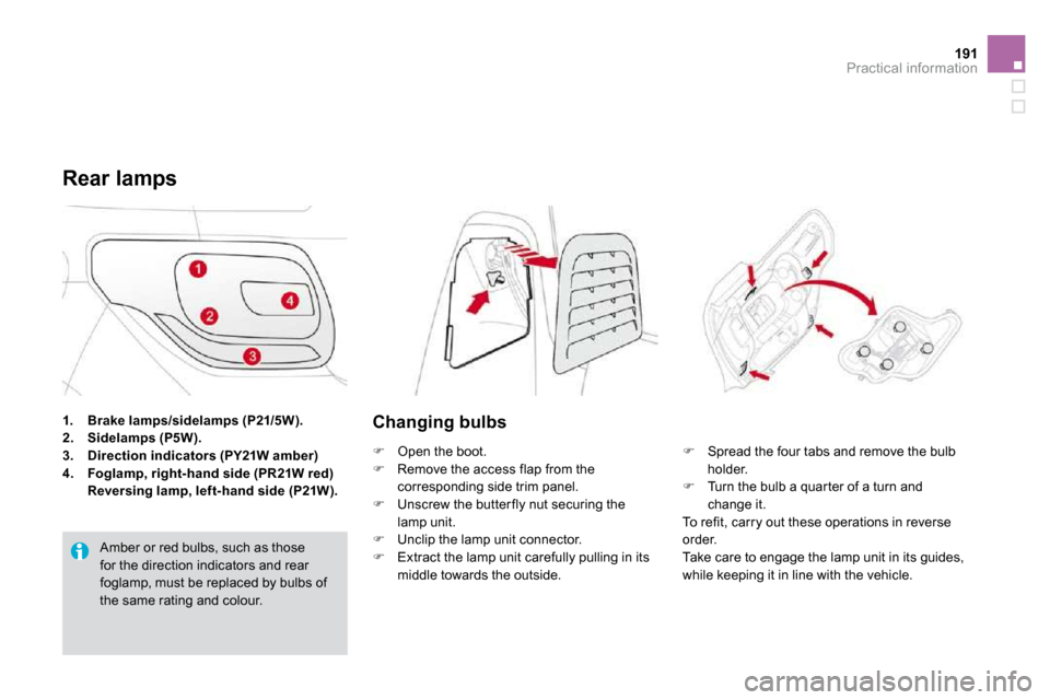
1. Brake lamps/sidelamps (P21/5W).2. Sidelamps (P5W).3. Direction indicators (PY21W amber)
4. Foglamp, right-hand side (PR21W red) Reversing lamp, left-hand side (P21W).
Rear lamps
Amber or red bulbs, such as those for the direction indicators and rear foglamp, must be replaced by bulbs of the same rating and colour.
Changing bulbs
� Open the boot. � Remove the access flap from the corresponding side trim panel. � Unscrew the butter fly nut securing the lamp unit. � Unclip the lamp unit connector. � Extract the lamp unit carefully pulling in its middle towards the outside.
� Spread the four tabs and remove the bulb holder. � Turn the bulb a quar ter of a turn and change it. To refit, carry out these operations in reverse order. Take care to engage the lamp unit in its guides, while keeping it in line with the vehicle.
Page 181 of 248
Changing a fuse
Installing electrical accessories
Your vehicle’s electrical system is designed to operate with standard or optional equipment. Before installing other electrical equipment or accessories on your vehicle, contact a CITROËN dealer.
CITROËN will not accept responsibility for the cost incurred in repairing your vehicle or for rectifying malfunctions resulting from the installation of accessories not supplied and not recommended by CITROËN and not installed in accordance with its instructions, in par ticular when the combined consumption of all of the additional equipment connected exceeds 10 milliamperes.
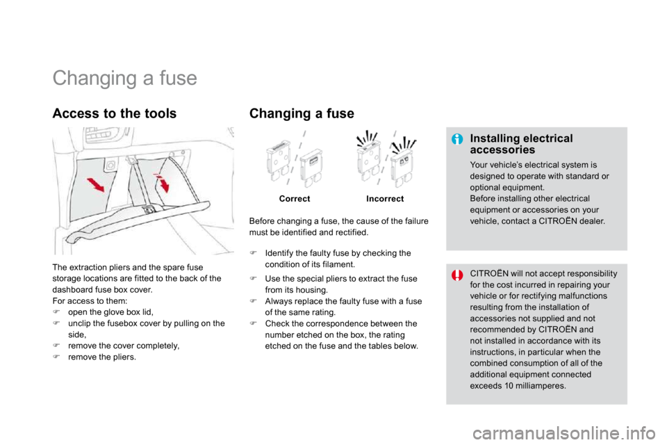
The extraction pliers and the spare fuse storage locations are fitted to the back of the dashboard fuse box cover.
For access to them: � open the glove box lid, � unclip the fusebox cover by pulling on the
side, � remove the cover completely, � remove the pliers.
Access to the tools
Before changing a fuse, the cause of the failure must be identified and rectified.
� Identify the faulty fuse by checking the condition of its filament.
Changing a fuse
CorrectIncorrect
� Use the special pliers to extract the fuse from its housing.
� Always replace the faulty fuse with a fuse of the same rating. � Check the correspondence between the number etched on the box, the rating etched on the fuse and the tables below.
Page 184 of 248
197Practical information
Engine compartment
fusebox
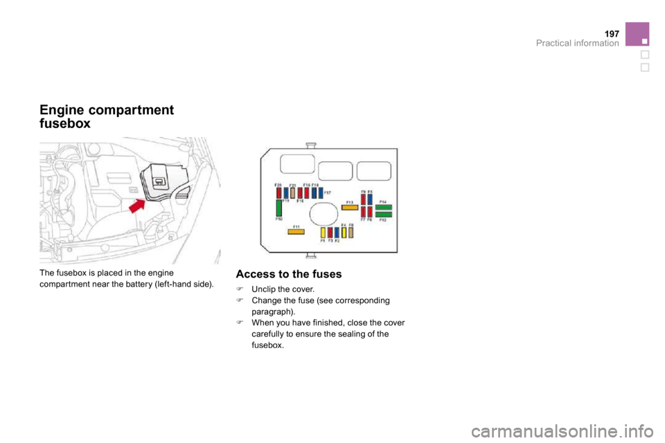
The fusebox is placed in the engine compar tment near the battery (left-hand side). Access to the fuses
� Unclip the cover.
� Change the fuse (see corresponding paragraph). � When you have finished, close the cover carefully to ensure the sealing of the fusebox.