ECU CITROEN DS3 CABRIO 2018 Handbook (in English)
[x] Cancel search | Manufacturer: CITROEN, Model Year: 2018, Model line: DS3 CABRIO, Model: CITROEN DS3 CABRIO 2018Pages: 248, PDF Size: 8.79 MB
Page 125 of 248
123
You can change mode at any time by
moving the gear selector from A to M or
vice-versa.
Never select neutral N when the vehicle
is moving.
Temporary control of gear changing
You can temporarily take over control of gear
changes using the steering mounted + and -
control paddles: if the engine speed allows, the
gear change is carried out.
This function allows you to anticipate certain
situations, such as overtaking another vehicle
or approaching a bend in the road.
Following a
few moments with no action on
the control paddles, the gearbox returns to
automatic operation.
Manual mode
F Select position M .
Reverse
To engage reverse gear, the vehicle must be
stationary with your foot on the brake pedal.
F
Sel
ect position R .
Stopping the vehicle
Before switching off the engine, you can:
-
c hange to position N to be in neutral, or
-
l
eave the vehicle in gear; in this case the
vehicle cannot be moved.
For all parking situations, you must apply
the parking brake to immobilise the
vehicle.
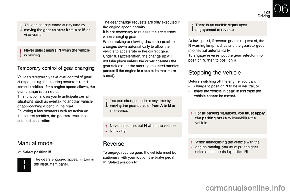
The gears engaged appear in turn in
the instrument panel. The gear change requests are only executed if
the engine speed permits.
It is not necessary to release the accelerator
when changing gear.
When braking or slowing down, the gearbox
changes down automatically to allow the
vehicle to accelerate in the correct gear.
Under full acceleration, the change up will
not take place unless the driver operates the
gear selector or the steering mounted paddles
(except if the engine is close to its maximum
speed).
You can change mode at any time by
moving the gear selector from A to M or
vice-versa.
Never select neutral N when the vehicle
is moving. There is an audible signal upon
engagement of reverse.
At low speed, if reverse gear is requested, the
N warning lamp flashes and the gearbox goes
into neutral automatically.
To engage reverse, put the gear selector into
position N , then to position R .
When immobilising the vehicle with the
engine running, you must put the gear
selector into neutral (position N ).
06
Driving
Page 140 of 248
138
Exceeding programmed
speed
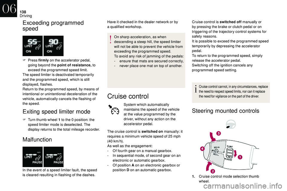
F Press firmly on the accelerator pedal,
going beyond the point of resistance, to
exceed the programmed speed limit.
The speed limiter is deactivated temporarily
and the programmed speed, which is still
displayed, flashes.
Return to the programmed speed, by means of
intentional or unintentional deceleration of the
vehicle, automatically cancels the flashing of
the speed.
Exiting speed limiter mode
F Turn thumb wheel 1 to the 0 position: the
speed limiter mode is deselected. The
display returns to the total mileage recorder.
Malfunction
In the event of a speed limiter fault, the speed
i s cleared resulting in flashing of the dashes. On sharp acceleration, as when
descending a
steep hill, the speed limiter
will not be able to prevent the vehicle from
exceeding the programmed speed.
To avoid any risk of jamming of the pedals:
-
e
nsure that mats are secured correctly,
-
n
ever place one mat on top of another.
Have it checked in the dealer network or by
a
qualified workshop.
Cruise control
System which automatically
maintains the speed of the vehicle
at the value programmed by the
driver, without any action on the
accelerator pedal.
Cruise control is switched off
manually or
by pressing the brake or clutch pedal or on
triggering of the trajectory control systems for
safety reasons.
It is possible to exceed the programmed speed
temporarily by depressing the accelerator
pedal.
To return to the programmed speed, simply
release the accelerator pedal.
Switching off the ignition cancels any
programmed speed setting.
Cruise control cannot, in any circumstances, replace
the need to respect speed limits, nor can it replace
the need for vigilance on the part of the driver.
Steering mounted controls
The cruise control is switched on manually: it
requires a minimum vehicle speed of 25 mph
(40
km/h).
As well as the engagement:
-
O
f fourth gear on a manual gearbox.
-
I
n sequential mode, of second gear on an
electronic or automatic gearbox.
-
O
f position A on an electronic gearbox or
position D on an automatic gearbox.
1.Cruise control mode selection thumb
wheel.
06
Driving
Page 142 of 248

140
Malfunction
In the event of a cruise control fault, the speed
i s cleared resulting in flashing of the dashes.
Have it checked by an authorised dealer or by
a
qualified workshop. When cruise control is active, be careful
when holding one of the speed setting
buttons: this may result in a
very rapid
change in the speed of your vehicle.
Do not use the cruise control on slippery
roads or in heavy traffic.
When descending a
steep hill, the cruise
control system cannot prevent the vehicle
from exceeding the programmed speed.
To avoid any risk of jamming the pedals:
-
E
nsure that mats are secured correctly.
-
D
o not fit one mat on top of another.
Active City Brake
Active City Brake is a driving assistance
s ystem that aims to avoid a frontal collision
or reduce the speed of an impact if the driver
does not react sufficiently (inadequate brake
application).
This system has been designed to
improve driving safety.
The driver must always check the traffic
and assess the distances and relative
speeds of other vehicles.
Active City Brake cannot in any
circumstances replace the need for
vigilance on the part of the driver.
Never look at the laser sensor through
an optical instrument (magnifying glass,
microscope, etc.) at a
distance of less
than 10
centimetres: risk of eye injury!
Principle
Using a laser sensor located at the top of the
w indscreen, this system detects a vehicle
running in the same direction or stationary
ahead of your vehicle.
When necessary, the vehicle's braking system
is operated automatically to avoid a
collision
with the vehicle ahead.
Automatic braking occurs later than if
done by the driver, so as to inter vene only
when there is a
high risk of collision.
Conditions of activation
Active City Brake functions if the following
conditions are met:
-
ig
nition on,
-
t
he vehicle is moving for ward,
-
t
he speed is between about 3 and 19 mph
(5
and 30 km/h),
06
Driving
Page 168 of 248

166
Access to the kit
This kit is installed in the under floor storage,
under the boot floor.
Composition of the kit
1.12 V compressor, with built-in pressure
gauge.
2. Bottle of sealant, with built-in hose.
3. Speed limit sticker.
Repair procedure
F Park the vehicle without obstructing any
traffic and apply the parking brake.
F
F
ollow the safety instructions (hazard
warning lamps, warning triangle, wearing
high visibility vest, etc.) according to the
legislation in force in the country where you
are driving.
F
S
witch off the ignition.
F
U
ncoil the pipe stowed under the
compressor.
Avoid removing any foreign bodies which
have penetrated the tyre. F
R
emove the valve cap from the tyre to be
repaired and keep it in a
clean place.
F
C
onnect the pipe from the compressor to
the bottle of sealant. F
T
urn over the sealant bottle and secure it in
the cut-out provided on the compressor.
F
C
onnect the hose from the bottle of sealant
to the valve of the tyre to be repaired and
tighten firmly.
08
In the event of a breakdown
Page 169 of 248
167
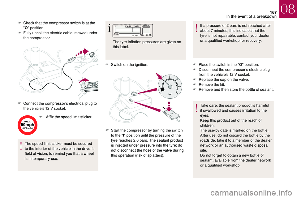
F Check that the compressor switch is at the "O " position.
F
F
ully uncoil the electric cable, stowed under
the compressor.
F
A
ffix the speed limit sticker.
The speed limit sticker must be secured
to the interior of the vehicle in the driver's
field of vision, to remind you that a
wheel
is in temporary use. F
S
witch on the ignition.If a
pressure of 2 bars is not reached after
about 7
minutes, this indicates that the
tyre is not repairable; contact your dealer
or a
qualified workshop for recovery.
F
C
onnect the compressor's electrical plug to
the vehicle's 12
V socket. The tyre inflation pressures are given on
this label.
F
S
tart the compressor by turning the switch
to the " l" position until the pressure of the
tyre reaches 2.0
bars. The sealant product
is injected under pressure into the tyre; do
not disconnect the hose of the valve during
this operation (risk of splatters). F
P
lace the switch in the "O" position.
F
D
isconnect the compressor's electric plug
from the vehicle's 12
V socket.
F
R
eplace the cap on the valve.
F
R
emove the kit.
F
R
emove and then store the bottle of sealant.
Take care, the sealant product is harmful
if swallowed and causes irritation to the
eyes.
Keep this product out of the reach of
children.
The use-by date is marked on the bottle.
After use, do not discard the bottle by the
roadside, take it to a
member of the dealer
network or an authorised waste disposal
site.
Do not forget to obtain a
new bottle of
sealant, available from the dealer network
or a
qualified workshop.
08
In the event of a breakdown
Page 171 of 248
169
If a pressure of 2 bars is not reached after
7 minutes, this indicates that the tyre is
not repairable; contact your dealer or
a
qualified workshop for recovery.
F
O
nce the correct pressure is reached, put
the switch to the " O" position.
F
R
emove the kit then stow it.
Do not drive more than 120
miles (200 km)
with a
temporarily repaired tyre; see your
dealer or a
qualified workshop to change
the tyre.
Should the pressure of one or more tyres
be adjusted, it is necessary to reinitialise
the under-inflation detection system.
For more information on Under-inflation
detection , refer to the corresponding
section.
Spare wheel
Scan the QR code on page 3 to view
e xplanatory videos.
Procedure for changing a
damaged wheel with
the spare wheel using the tools provided with
the vehicle.
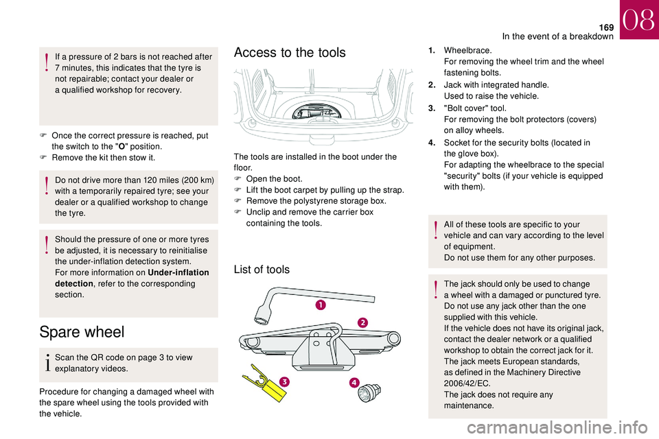
Access to the tools
List of tools
1. Wheelbrace.
For removing the wheel trim and the wheel
fastening bolts.
2. Jack with integrated handle.
Used to raise the vehicle.
3. "Bolt cover" tool.
For removing the bolt protectors (covers)
on alloy wheels.
4. Socket for the security bolts (located in
the glove box).
For adapting the wheelbrace to the special
"security" bolts (if your vehicle is equipped
with them).
All of these tools are specific to your
vehicle and can vary according to the level
of equipment.
Do not use them for any other purposes.
The jack should only be used to change
a
wheel with a damaged or punctured tyre.
Do not use any jack other than the one
supplied with this vehicle.
If the vehicle does not have its original jack,
contact the dealer network or a
qualified
workshop to obtain the correct jack for it.
The jack meets European standards,
as defined in the Machinery Directive
2006/42/EC.
The jack does not require any
maintenance.
The tools are installed in the boot under the
f l o o r.
F
O
pen the boot.
F
L
ift the boot carpet by pulling up the strap.
F
R
emove the polystyrene storage box.
F
U
nclip and remove the carrier box
containing the tools.
08
In the event of a breakdown
Page 173 of 248
171
Removing a wheel
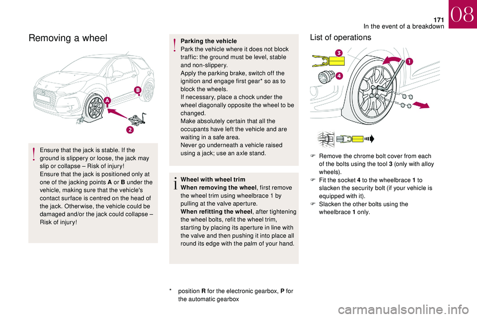
Ensure that the jack is stable. If the
ground is slippery or loose, the jack may
slip or collapse – Risk of injury!
Ensure that the jack is positioned only at
one of the jacking points A or B under the
vehicle, making sure that the vehicle's
contact sur face is centred on the head of
the jack. Otherwise, the vehicle could be
damaged and/or the jack could collapse –
Risk of injury!
*
position R for the electronic gearbox, P for
the automatic gearbox Parking the vehicle
Park the vehicle where it does not block
traffic: the ground must be level, stable
and non-slippery.
Apply the parking brake, switch off the
ignition and engage first gear* so as to
block the wheels.
If necessary, place a
chock under the
wheel diagonally opposite the wheel to be
changed.
Make absolutely certain that all the
occupants have left the vehicle and are
waiting in a safe area.
Never go underneath a vehicle raised
using a jack; use an axle stand.
Wheel with wheel trim
When removing the wheel , first remove
the wheel trim using wheelbrace 1
by
pulling at the valve aperture.
When refitting the wheel , after tightening
the wheel bolts, refit the wheel trim,
starting by placing its aperture in line with
the valve and then pushing it into place all
round its edge with the palm of your hand.
List of operations
F Remove the chrome bolt cover from each of the bolts using the tool 3 (only with alloy
w h e e l s).
F
F
it the socket 4 to the wheelbrace 1 to
slacken the security bolt (if your vehicle is
equipped with it).
F
S
lacken the other bolts using the
wheelbrace 1
o n l y.
08
In the event of a breakdown
Page 175 of 248

173
Fitting the "space-saver " spare wheel
If your vehicle is fitted with alloy wheels,
when tightening the bolts on fitting, it is
normal to notice that the washers do not
come into contact with the "space-saver"
spare wheel. The wheel is secured by the
conical contact of each bolt.
After changing a
wheel
Do not exceed 50
mph (80 km/h) when
driving with the "space-saver" type spare
wheel fitted.
Visit the dealer network or a
qualified
workshop as soon as possible to have the
tightness of the bolts and the pressure of
the spare wheel checked.
Have the punctured wheel checked. After
inspection, the technician will let you know
if the tyre can be repaired or if it must be
replaced.List of operations
F Put the wheel in place on the hub.
F S crew in the bolts by hand to the stop.
F
P
re-tighten the security bolt (if your vehicle
is so equipped) using the wheelbrace
1
fitted with the security socket 4 .
F
P
re-tighten the other bolts using the
wheelbrace 1
o n l y.
F
N
ow lower the vehicle fully.
F
F
old the jack 2 and detach it. F
T
ighten fully the security bolt (if your vehicle
is so equipped) using the wheelbrace
1 fitted with the security socket 4
.
F T ighten the other bolts using the
wheelbrace 1 o n l y.
F
P
ut the chrome bolt covers back on each of
the bolts (only with alloy wheels).
F
S
tore the tools in the box.
08
In the event of a breakdown
Page 183 of 248
181
Changing a fuse
Access to the tools
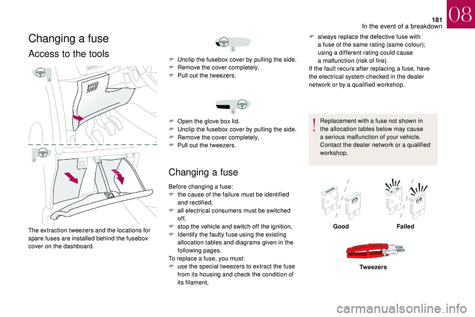
The extraction tweezers and the locations for
spare fuses are installed behind the fusebox
cover on the dashboard.
Changing a fuse
F always replace the defective fuse with
a fuse of the same rating (same colour);
using a
different rating could cause
a
malfunction (risk of fire).
If the fault recurs after replacing a
fuse, have
the electrical system checked in the dealer
network or by a
qualified workshop.
Replacement with a
fuse not shown in
the allocation tables below may cause
a
serious malfunction of your vehicle.
Contact the dealer network or a
qualified
workshop.
F
U
nclip the fusebox cover by pulling the side.
F
R
emove the cover completely,
F
P
ull out the tweezers.
F
O
pen the glove box lid.
F
U
nclip the fusebox cover by pulling the side.
F
R
emove the cover completely,
F
P
ull out the tweezers.
Before changing a
fuse:
F
t
he cause of the failure must be identified
and rectified,
F
a
ll electrical consumers must be switched
of f,
F
s
top the vehicle and switch off the ignition,
F
I
dentify the faulty fuse using the existing
allocation tables and diagrams given in the
following pages.
To replace a
fuse, you must:
F
u
se the special tweezers to extract the fuse
from its housing and check the condition of
its filament, Good
Failed
Tw e e z e r s
08
In the event of a breakdown
Page 191 of 248
189
Access to the battery
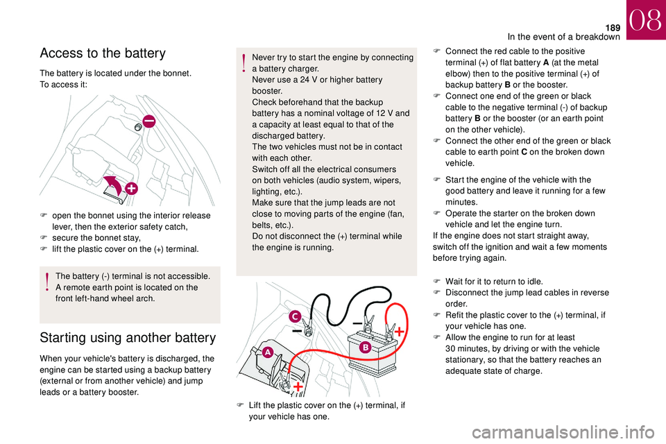
The battery is located under the bonnet.
To access it:
F
o
pen the bonnet using the interior release
lever, then the exterior safety catch,
F
s
ecure the bonnet stay,
F
l
ift the plastic cover on the (+) terminal.The battery (-) terminal is not accessible.
A remote earth point is located on the
front left-hand wheel arch.
Starting using another battery
When your vehicle's battery is discharged, the
engine can be started using a backup battery
(external or from another vehicle) and jump
leads or a
battery booster. Never try to start the engine by connecting
a
battery charger.
Never use a 24 V or higher battery
b o o s t e r.
Check beforehand that the backup
battery has a nominal voltage of 12 V and
a capacity at least equal to that of the
discharged battery.
The two vehicles must not be in contact
with each other.
Switch off all the electrical consumers
on both vehicles (audio system, wipers,
lighting, etc.).
Make sure that the jump leads are not
close to moving parts of the engine (fan,
belts, etc.).
Do not disconnect the (+) terminal while
the engine is running. F
C
onnect the red cable to the positive
terminal (+) of flat battery A (at the metal
elbow) then to the positive terminal (+) of
backup battery B or the booster.
F
C
onnect one end of the green or black
cable to the negative terminal (-) of backup
battery B or the booster (or an earth point
on the other vehicle).
F
C
onnect the other end of the green or black
cable to earth point C on the broken down
vehicle.
F
L
ift the plastic cover on the (+) terminal, if
your vehicle has one. F
S
tart the engine of the vehicle with the
good battery and leave it running for a few
minutes.
F
O
perate the starter on the broken down
vehicle and let the engine turn.
If the engine does not start straight away,
switch off the ignition and wait a few moments
before trying again.
F
W
ait for it to return to idle.
F
D
isconnect the jump lead cables in reverse
o r d e r.
F
R
efit the plastic cover to the (+) terminal, if
your vehicle has one.
F
A
llow the engine to run for at least
30 minutes, by driving or with the vehicle
stationary, so that the battery reaches an
adequate state of charge.
08
In the event of a breakdown