door CITROEN DS3 CROSSBACK 2020 Workshop Manual
[x] Cancel search | Manufacturer: CITROEN, Model Year: 2020, Model line: DS3 CROSSBACK, Model: CITROEN DS3 CROSSBACK 2020Pages: 244, PDF Size: 7.7 MB
Page 128 of 244
126
Driving06
an obstacle is detected, or by driver action. If the
driver notices a hazard, they may also interrupt
the manoeuvre permanently.
To suspend the manoeuvre, the driver can:
–
R
elease the function control button.
–
Depre
ss the brake pedal.
–
R
esume control of the steering.
–
C
hange the gearbox status (except changing
to P).
The vehicle is immediately immobilised if the
manoeuvre is suspended.
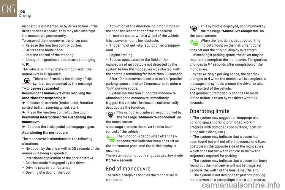
This is confirmed by the display of this
symbol, accompanied by the message
"Manoeuvre suspended".
Resuming the manoeuvre after resolving the
conditions for suspending it:
► Release all controls (brake pedal, function
control button, steering wheel, etc.).
► Press the function control button again.
Permanent interruption after suspending the
manoeuvre:
► Depress the brake pedal and engage a gear.
Abandoning the manoeuvre
The manoeuvre is abandoned in the following
situations:
–
No action b
y the driver within 30 seconds of the
manoeuvre being suspended.
–
In
tentional application of the parking brake.
–
Gearbo
x mode P engaged by the driver.
–
D
river's seat belt unfastened.
–
O
pening of a door or the boot. –
Activ
ation of the direction indicator lamps on
the opposite side to that of the manoeuvre.
–
In c
ertain cases, when a wheel of the vehicle
hits a pavement or a low obstacle.
–
Triggering o
f anti-slip regulation on a slippery
road.
–
Engine st
alling.
–
Sudden appearanc
e in the field of the
manoeuvre of an obstacle not detected by the
system before the manoeuvre was started, with
the obstacle remaining for more than 30 seconds.
–
A
fter 10 manoeuvres to enter or exit a "parallel"
parking space and after 7 manoeuvres to enter a
"bay" parking space,
–
Sy
stem malfunction during the manoeuvre.
Abandoning the manoeuvre immediately
triggers the vehicle’s brakes and automatically
deactivates the function.
This symbol is displayed, accompanied by
the message "Manoeuvre abandoned" on
the touch screen.
A message prompts the driver to take back
control of the vehicle.
The function is deactivated after a few
seconds; this indicator lamp goes off on
the instrument panel and the initial display is
resumed.
The system automatically engages gearbox mode
P after 4 seconds.
End of manoeuvre
The vehicle stops as soon as the manoeuvre is
completed.
This symbol is displayed, accompanied by
the message "Manoeuvre completed" on
the touch screen.
When the function is deactivated, this
indicator lamp on the instrument panel
goes off and the original display is restored.
–
If en
tering a parking space, the driver may be
required to complete the manoeuvre. The gearbox
changes to P 4 seconds after completion of the
manoeuvre.
–
When e
xiting a parking space, the gearbox
changes to N when the manoeuvre is complete. A
message and symbols prompt the driver to take
back control of the vehicle.
The gearbox automatically changes to mode
P if no action is taken by the driver within 30
secondss.
Operating limits
– The system may suggest an inappropriate
parking space (parking prohibited, work in
progress with damaged road surface, location
alongside a ditch, etc.).
–
The s
ystem may indicate that a space has
been found but will not offer it because of a fixed
obstacle on the opposite side of the manoeuvre,
which does not allow the vehicle to follow the
trajectory required for parking.
–
The s
ystem may indicate that a space has been
found but the manoeuvre will not be triggered
because the width of the lane is insufficient.
–
The s
ystem is not designed to perform parking
manoeuvres on a steep slope or on a sharp curve.
– The system does not detect spaces that
are much larger than the vehicle itself or that
are delimited by obstacles that are too low
(pavements, studs, etc.) or too thin (trees, posts,
wire fences, etc.).
– The system may be impaired by incorrect
inflation of the vehicle’s tyres.
– The tilting of the vehicle if the boot is heavily
loaded can affect the distance measurements.
Do not use the function under the
following exterior conditions:
– Alongside a soft shoulder (ditch) or quay or
on the edge of a drop.
– When the road surface is slippery (ice).
Do not use the function in the presence of
one of the following malfunctions:
– If a tyre is under-inflated.
– If one of the bumpers is damaged.
– If one of the cameras is faulty.
– If the brake lamps are not working.
Do not use the function if the vehicle has
been subject to one of the following
modifications:
– When carrying an object extending beyond
the dimensions of the vehicle (ladder on the
roof bars, bicycle carrier on the tailgate, etc.).
– With a non-approved towball in place.
– With snow chains fitted.
– When driving on a small-diameter or "space-
saver" type spare wheel.
Page 137 of 244

135
Practical information07
If in doubt
Domestic or accelerated charging: do
not remain inside or near the vehicle, or near
the charging cable or charging unit, even for a
short time.
Fast charging: do not use the system yourself
and avoid approaching public fast charging
points. Leave the area and ask a third party to
recharge the vehicle.
For domestic or accelerated charging
Before charging
Depending on the context:
► Have a professional check that the
electrical system to be used complies with
applicable standards and is compatible with
the vehicle.
► Have a professional electrician install
a dedicated domestic power socket or
accelerated charging unit (Wallbox)
compatible with the vehicle.
Use the charging cable supplied with the
vehicle.
(During charging)
Never work under the bonnet:
–
Some areas remain v
ery hot, even an hour
after charging ends - risk of burns!
–
The fan ma
y start at any time - risk of cuts or
strangulation!
After charging
Check that the charging flap is closed.
Do not leave the cable connected to the
domestic power socket - risk of short-circuit
or electrocution in the event of contact with or
immersion in water!
For fast charging
Before charging
Check that the fast public charger and
its charging cable are compatible with your
vehicle.
If the exterior temperature is below :
–
-25
°C, charging may not be possible.
–
0°C
, charging times may be extended.
(During charging)
Do not remain in or near the vehicle.
While charging is in progress, opening the
driver's door will interrupt charging.
After charging
Check that the charging flap is closed.
Connection
► Before charging, check that the drive selector
is in mode P and the ignition is off, otherwise
charging is not possible. ►
Open the charging flap by pressing the push-
button, and check that there are no foreign bodies
on the charging connector.
Domestic charging
► Connect the charging cable from the control
unit to the domestic socket.
When the connection is made, all of the indicator
lamps on the control unit light up, then only the
POWER indicator lamp remains on in green.
► Remove the protective cover from the
charging nozzle.
► Insert the nozzle into the charging connector.
The start of charging is confirmed by the flashing
in green of the CHARGE indicator lamps in the
flap, then on the control unit.
If this is not the case, charging has not started;
restart the procedure, ensuring that all
connections are properly established.
Page 138 of 244

136
Practical information07
The red indicator lamp in the flap comes on to
indicate that the nozzle is locked.
If charging has finished but the cable is
still connected, opening the driver's door
restarts charging for around 20 seconds.
Accelerated charging
► Follow the instructions for use of the
accelerated charging unit (Wallbox).
► Remove the protective cover from the
charging nozzle.
► Insert the nozzle into the charging connector.
The start of charging is confirmed when the
charging indicator lamp in the flap flashes green.
If this is not the case, charging has not started;
restart the procedure, ensuring that the nozzle is
inserted correctly.
The red indicator lamp in the flap comes on to
indicate that the nozzle is locked.
Fast charging
► Depending on version, remove the protective
cover from the base.
► Connect the charging cable to the vehicle
connector, following the instructions for use of
the fast public charger.
The start of charging is confirmed when the
charging indicator lamp in the flap flashes green.
If this is not the case, charging has not started;
restart the procedure, ensuring that the
connection is correct.
The red indicator lamp in the flap comes on to
indicate that the nozzle is locked.
Disconnection
Before disconnecting the nozzle from the
charging connector:
► If the vehicle is unlocked, lock it and then
unlock it.
► If the vehicle is locked, unlock it. The red indicator lamp in the flap goes out to
confirm that the charging nozzle is unlocked.
►
Within 30 seconds, remove the charging
nozzle.
Domestic charging
When charging is complete, the green CHARGE
indicator lamp on the control unit comes on fixed.
► Replace the protective cover on the charging
nozzle and close the charging flap.
► Disconnect the control unit end of the
charging cable from the domestic socket.
Accelerated charging
The end of charging is indicated by the charging
control unit and by the fixed lighting of the green
indicator lamp in the flap.
► Hang up the nozzle on the charging unit and
close the charging flap.
Fast charging
The end of charging is indicated by the charger
and by the fixed lighting of the green indicator
lamp in the flap.
► Hang up the nozzle on the charging station.
► Depending on version, replace the protective
cover on the base and close the charging flap.
Towing device
Load distribution
► Distribute the load in the trailer so that
the heaviest items are as close as possible to
the axle, and the nose weight approaches the
maximum permitted without exceeding it.
Air density decreases with altitude, thus reducing
engine performance. The maximum load which
can be towed must be reduced by 10% per
1,000 metres of altitude.
Use towing devices and their genuine
wiring harnesses approved by the
Manufacturer. It is recommended that the
Page 139 of 244

137
Practical information07
Accelerated charging
The end of charging is indicated by the charging
control unit and by the fixed lighting of the green
indicator lamp in the flap.
► Hang up the nozzle on the charging unit and
close the charging flap.
Fast charging
The end of charging is indicated by the charger
and by the fixed lighting of the green indicator
lamp in the flap.
► Hang up the nozzle on the charging station.
► Depending on version, replace the protective
cover on the base and close the charging flap.
Towing device
Load distribution
► Distribute the load in the trailer so that
the heaviest items are as close as possible to
the axle, and the nose weight approaches the
maximum permitted without exceeding it.
Air density decreases with altitude, thus reducing
engine performance. The maximum load which
can be towed must be reduced by 10% per
1,000 metres of altitude.
Use towing devices and their genuine
wiring harnesses approved by the
Manufacturer. It is recommended that the
fitting be performed by a dealer or a qualified
workshop.
If not fitted by a dealer, it must still be fitted
in accordance with the Manufacturer's
instructions.
Certain driving or manoeuvring aid functions
are automatically deactivated if an approved
towing system is used.
Observe the maximum authorised towable
weight, indicated on the vehicle's
registration certificate, the manufacturer's
label as well as in the Technical data section of
this guide.
Complying with the maximum authorised
nose weight (towball) also includes the use of
accessories (bicycle carriers, tow boxes, etc.).
Observe the legislation in force in the
country where you are driving.
Electric motor
Electric vehicles must never be equipped
with towing devices.
It is therefore not possible to tow a trailer or
caravan.
Roof bars
As a safety measure and to avoid
damaging the roof, it is essential to use
the transverse bars approved for the vehicle.
Observe the instructions on fitting and use
contained in the guide supplied with the roof
bars.
To install the roof bars, you must secure them
only to the four fixing points on the roof frame.
These points are concealed by the vehicle's doors
when they are closed.
The roof bar fixings include a lug to be fitted into
the hole at each fixing point.
Maximum load distributed over the roof
bars, for a loading height not exceeding
40 cm: 75 kg.
As this value may change, please verify the
maximum load set out in the manual supplied
with the roof bars.
Page 141 of 244
139
Practical information07
Exiting the mode
These functions are automatically reactivated the
next time the vehicle is used.
To restore the use of these functions immediately,
start the engine and let it run:
–
For le
ss than 10 minutes, to use the equipment
for approximately 5 minutes.
–
For more than 10 minut
es, to use the equipment
for approximately 30 minutes.
Let the engine run for the specified duration to
ensure that the battery charge is sufficient.
To recharge the battery, avoid repeatedly or
continuously restarting the engine.
A flat battery prevents the engine from
starting.
For more information on the 12 V battery, refer
to the corresponding section.
Load reduction mode
This system manages the use of certain functions
according to the level of charge remaining in the
battery.
When the vehicle is being driven, the load
reduction function temporarily deactivates
certain functions, such as the air conditioning
and the heated rear screen.
The deactivated functions are reactivated
automatically as soon as conditions permit.
Bonnet
Stop & Start
Before doing anything under the bonnet,
you must switch off the ignition to avoid any
risk of injury resulting from an automatic
change to START mode.
The location of the interior bonnet release
lever prevents the bonnet being opened
when the left-hand front door is closed.
When the engine is hot, handle the
exterior safety catch and the bonnet stay
with care (risk of burns), using the protected
area.
When the bonnet is open, take care not to
damage the safety catch.
Do not open the bonnet under very windy
conditions.
Cooling of the engine when stopped
The engine cooling fan may start after the
engine has been switched off.
Take care with objects or clothing that could
be caught in the blades of the fan!
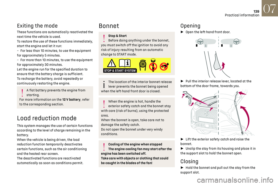
Opening
► Open the left-hand front door.
► Pull the interior release lever, located at the
bottom of the door frame, towards you.
► Lift the exterior safety catch and raise the
bonnet.
► Unclip the stay from its housing and place it in
the support slot to hold the bonnet open.
Closing
► Hold the bonnet and pull out the stay from the
support slot.
Page 147 of 244

145
Practical information07
Recommendations on storage
AdBlue® freezes at about -11°C and deteriorates
above +25°C. Containers should be stored in a
cool area and protected from direct sunlight.
Under these conditions, the fluid can be kept for
at least a year.
If the fluid has frozen, it can be used once it has
completely thawed out at room temperature.
Never store AdBlue® containers in your
vehicle.
Precautions for use
AdBlue® is a urea-based solution. This fluid is non-
flammable, colourless and odourless (when kept
in a cool place).
In the event of contact with the skin, wash the
affected area with soap and running water. In the
event of contact with the eyes, immediately rinse
the eyes with large amounts of water or with an
eye wash solution for at least 15 minutes. Seek
medical attention if you feel a persistent burning
sensation or irritation.
If swallowed, immediately wash out the mouth
with clean water and then drink plenty of water.
In certain conditions (high temperature, for
example), the risk of release of ammonia cannot
be excluded: do not inhale the fluid. Ammonia
vapours have an irritant effect on mucous
membranes (eyes, nose and throat).
Store AdBlue® out of the reach of children,
in its original container.
Procedure
Before starting the top-up procedure, ensure that
the vehicle is parked on a flat and level surface.
In wintry conditions, ensure that the temperature
of the vehicle is above -11 °C. Otherwise, the
AdBlue
® may be frozen and therefore cannot be
poured into its tank. Park your vehicle in a warmer
area for a few hours to allow the top-up to be
carried out.
Never pour AdBlue® into the Diesel fuel
tank.
If any AdBlue® is splashed, or if there are
any spillages on the bodywork, rinse
immediately with cold water or wipe with a
damp cloth.
If the fluid has crystallised, clean it off using a
sponge and hot water.
Important: in the event of a top-up after an
AdBlue breakdown, you must wait about
5 minutes before switching on the ignition,
without opening the driver's door, unlocking
the vehicle or bringing the electronic key into
the passenger compartment.
Switch on the ignition, then wait for 10
seconds before starting the engine.
► Press the "START/STOP" button to switch off
the engine.
► Turn the blue cap of the AdBlue® tank a 6th of a
turn anti-clockwise and remove it.
► With a container of AdBlue
®: after checking
the expiry date, read carefully the instructions
on the label before pouring the contents of the
container into the vehicle's AdBlue tank.
► With an AdBlue
® pump: introduce the nozzle
and fill the tank until the automatic cut-off of the
nozzle.
In order not to overfill the AdBlue® tank:
–
Add betw
een 10 and 13 litres using
AdBlue
® containers.
–
St
op after the nozzle’s first automatic cut-
out, if you are refilling at a service station.
If the AdBlue® tank is completely empty
– which is confirmed by the “Top
up AdBlue: Starting impossible” message – it is
essential to add at least 5 litres.
Page 148 of 244

146
Practical information07
Do not dispose of AdBlue® containers in
the household waste.
Place them in a container reserved for this
purpose or take them back to where you
bought them.
Free-wheeling
In certain situations, you must allow the vehicle to
free-wheel (while being towed, on a rolling road,
in an automatic car wash, or being transported by
rail or sea freight, etc.).
The procedure varies according to the type of
gearbox and parking brake.
With a manual gearbox and
electric parking brake
/
Release procedure
► With the engine running and while depressing
the brake pedal, move the gear selector to the
neutral position.
► While depressing the brake pedal, switch off
the ignition.
► Release the brake pedal, then switch on the
ignition again.
► While depressing the brake pedal, press the
control lever to release the parking brake.
► Release the brake pedal, then switch off the
ignition.
Reverting to normal operation
► While depressing the brake pedal, start the
engine.
With EAT8 automatic gearbox
or drive selector and electric
parking brake
/
Release procedure
► With the vehicle stationary and the engine
running, select mode N and switch off the
ignition.
Within 5 seconds:
► Switch on the ignition again.
► While depressing the brake pedal, move the
push selector forwards or backwards to confirm
mode N.
► While depressing the brake pedal, press the
control lever to release the parking brake.
► Release the brake pedal, switch off the
ignition.
If the 5-second time limit is exceeded, the gearbox
engages mode P; it is then necessary to restart
the procedure.
Reverting to normal operation
► While depressing the brake pedal, restart the
engine.
Keyless Entry and Starting
You must not depress the brake pedal
while switching the ignition on or off. If you do,
the engine will start, requiring you to restart
the procedure.
Advice on care and
maintenance
General recommendations
Observe the following recommendations to avoid
damaging your vehicle.
Exterior
Never use a high-pressure jet wash in the
engine compartment, due to the risk of
damaging electrical components.
Do not wash the vehicle in strong sunshine or
extremely cold conditions.
When washing the vehicle at an
automatic roller-brush car wash, be sure
to lock the doors and, depending on version,
remove the electronic key and deactivate the
“hands-free” function (“Hands-Free Tailgate
Access”).
When using a pressure washer, hold the lance
at least 30 cm from the vehicle (particularly
when cleaning areas containing chipped paint,
sensors or seals).
Page 162 of 244

160In the event of a breakdown08
The Manufacturer accepts no
responsibility for the cost incurred in
repairing your vehicle or for rectifying
malfunctions resulting from the installation of
accessories not supplied and not
recommended and not installed in accordance
with specifications, in particular when the
combined power consumption of all of the
additional equipment connected exceeds 10
milliamperes.
Fuses in the dashboard
The fusebox is located in the lower dashboard
(left-hand side).
To access the fuses, follow the same procedure
as that described for accessing the tool kit for
changing fuses.
For more information on Access to the tool kit,
refer to the corresponding section.
Fuse tables
Box 1
Fuse N° Rating (A) Functions
F1 10AElectrochrome
interior rear view
mirror, radar,
electric power
steering.
F5 20 ARear
screenwash
pump.
F6 20 AFront
screenwash
pump.
F12 7.5 A Diagnostic
socket.
Fuse N° Rating (A) Functions
F14 5 AEmergency and
assistance calls,
alarm control
unit.
F19 3 ATrailer interface
unit, top of
steering column.
F24 5 AHi-Fi amplifier,
parking sensors,
camera, touch
screen.
Box 2
Fuse N° Rating (A) Functions
F1 40 AHeated rear
screen.
F2 10AHeated door
mirrors.
F3 30 AFront electric
windows.
Fuse N° Rating (A) Functions
F5 30 ARear electric
windows.
F6 10 AFolding door
mirrors.
F7 10 AFolding door
mirrors.
F8 20 ALeft-hand side
retractable
handles.
F9 25 AHi-Fi amplifier.
F10 20 ARight-hand side
retractable
handles.
Engine compartment fuses
The fusebox is placed in the engine compartment
near the battery.
Page 163 of 244

161In the event of a breakdown08
Fuse N° Rating (A) FunctionsF5 30 ARear electric
windows.
F6 10 AFolding door
mirrors.
F7 10 AFolding door
mirrors.
F8 20 ALeft-hand side
retractable
handles.
F9 25 AHi-Fi amplifier.
F10 20 ARight-hand side
retractable
handles.
Engine compartment fuses
The fusebox is placed in the engine compartment
near the battery.
Accessing the fuses
► Release the two latches A.
► Remove the cover.
► Replace the fuse.
► When you have finished, close the cover
carefully, then engage the two latches A to ensure
that the fusebox is properly sealed.
Fuse tables
Fuse N° Rating (A) Functions
F16 15 A Full LED right-
hand main beam
headlamp.
F18 10AHalogen right-
hand main beam
headlamp.
F19 10 A or 15 A
(depending on version) Halogen left-
hand main beam
headlamp or Full
LED left-hand
main beam
headlamp.
F29 40 A Windscreen
wipers.
F32 80 A Power supply.
12 V battery / Accessory
battery
Procedure for starting the engine using another
battery or charging a discharged battery.
Lead-acid starter batteries
These batteries contain harmful
substances (sulphuric acid and lead).
They must be disposed of in accordance
with regulations and must never under any
Page 166 of 244
164In the event of a breakdown08
► At the end of the charging operation, switch
off charger B before disconnecting the cables
from battery A.
24v 12v
If this label is present, use only a 12 V
charger to avoid causing irreversible
damage to the electrical components related
to the Stop & Start system.
Never try to charge a frozen battery - risk
of explosion!
If the battery has frozen, have it checked by
a dealer or by a qualified workshop who will
verify that the internal components have not
been damaged and that the case has not
cracked, which would mean a risk of toxic and
corrosive acid leaking.
Some functions, including Stop & Start,
are not available if the battery is not
sufficiently charged.
Disconnecting the battery
In order to maintain an adequate state of charge
for starting the engine, it is recommended that
the battery be disconnected if the vehicle is taken
out of service for a long period. Before disconnecting the battery:
►
Close all openings (doors, boot, windows,
roof).
► Switch off all electrical consumers (audio
system, wipers, lighting, etc.).
► Switch off the ignition and wait for 4 minutes.
At the battery, it is only necessary to disconnect
the (+) terminal.
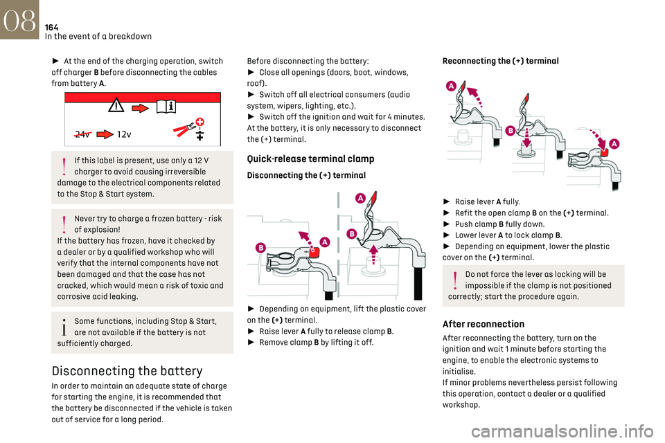
Quick-release terminal clamp
Disconnecting the (+) terminal
► Depending on equipment, lift the plastic cover
on the (+) terminal.
► Raise lever A fully to release clamp B.
► Remove clamp B by lifting it off.
Reconnecting the (+) terminal
► Raise lever A fully.
► Refit the open clamp B on the (+) terminal.
► Push clamp B fully down.
► Lower lever A to lock clamp B.
► Depending on equipment, lower the plastic
cover on the (+) terminal.
Do not force the lever as locking will be
impossible if the clamp is not positioned
correctly; start the procedure again.
After reconnection
After reconnecting the battery, turn on the
ignition and wait 1 minute before starting the
engine, to enable the electronic systems to
initialise.
If minor problems nevertheless persist following
this operation, contact a dealer or a qualified
workshop.
Referring to the relevant section, reset certain
equipment:
– Electronic key.
– Electric windows.
– Date and time.
– Preset radio stations.
After reconnection of the battery, the
“Collision risk detection system fault”
message is displayed on the instrument panel
when the ignition is switched on. This
operation is perfectly normal. The message
will disappear while driving.
The Stop & Start system may not be
operational during the trip following the
first engine start.
In this case, the system will only be
available again after a continuous period of
immobilisation of the vehicle, a period which
depends on the exterior temperature and the
Towing constraints
Type of vehicle
(engine / gearbox)gearbox Font wheels on the ground Rear wheels on the ground Flatbed
4 wheels on the ground with
towbar
Internal combustion /
Manual
Internal combustion /
Automatic