ECU CITROEN DS3 CROSSBACK 2022 User Guide
[x] Cancel search | Manufacturer: CITROEN, Model Year: 2022, Model line: DS3 CROSSBACK, Model: CITROEN DS3 CROSSBACK 2022Pages: 244, PDF Size: 7.7 MB
Page 79 of 244

77Safety05
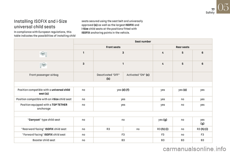
Installing ISOFIX and i-Size
universal child seats
In compliance with European regulations, this
table indicates the possibilities of installing child seats secured using the seat belt and universally
approved (a)
as well as the largest ISOFIX and
i-Size child seats at the positions fitted with
ISOFIX anchoring points in the vehicle.
Seat number
Front seats Rear seats
13 456
3 1456
Front passenger airbag Deactivated “OFF”
(b) Activated “ON” (c)
Position compatible with a universal child seat (a) no
yes (d) (f) yes yes (e)yes
Position compatible with an i-Size child seat no yesyesnoyes
Position equipped with a TOP TETHER anchorage no
yes yesnoyes
"Carrycot" type child seat nonoyes (g)noyes
(g)
"Rearward facing" ISOFIX child seat noR3 noR3 (h) (i) no R3 (h) (i)
"Forward facing" ISOFIX child seat noF3F3no F3
Booster child seat noB3 B3B3B3
Page 80 of 244

78Safety05
– F2X: ISOFIX child seat for toddlers.
– F2: ISOFIX reduced height child seat.
– F3: ISOFIX full height child seat.
Child booster seat.
ISOFIX "carrycot" type child seat:
– L1: head to the left.
– L2: head to the right.
Manual child lock
This system prevents opening of a rear door using
its interior handle.
The control, red in colour, is located on the edge of
each rear door (marked by a label).
Locking / Unlocking
► To lock, turn the red control as far as it will go
using the integral key: • To the right on the left-hand rear door.
Rules:
–
A po sition that is i-Size compatible is also
compatible for R1, R2 and F2X, F2, B2.
–
A po
sition that is R3 compatible is also
compatible for R1 and R2.
–
A po
sition that is F3 compatible is also
compatible for F2X and F2.
–
A po
sition that is B3 compatible is also
compatible for B2.
(a) Universal child seat: child seat that can be
installed in all vehicles using the seat belt.
(b) To install a "rearward facing" at this seat
position, the front passenger airbag must be
deactivated "OFF" .
(c) Only a "forward facing" child seat is
authorised at this seat position with the front
passenger airbag activated "ON".
(d) For a seat with height adjustment, adjust
the seat to the highest position and move it
fully back.
(e) Never install a child seat with a support leg
on the centre rear passenger seat.
(f) For a seat without height adjustment, the
backrest must be upright.
(g) Installing a “Carrycot” type child seat on
this seat may prevent the installation of
additional child seats in the rear. (h)
Adjust the driver's seat to the highest
position.
(i) Adjust the front passenger seat to the fully
forward position.
KeySeat position where the installation of a
child seat is forbidden.
Front passenger airbag deactivated.
Front passenger airbag activated.
Seat position suitable for the installation
of a child seat secured using the seat belt
and universally approved "rearward facing" and/
or "forward facing".
Seat position suitable for the installation a
child seat secured using the seat belt and
universally approved "forward facing".
Seat position where securing an i-Size
child seat is authorised.
Seat position where securing a "forward
facing" i-Size child seat is authorised.
Presence of a TOP TETHER anchoring point
at the rear of the backrest, authorising the
attachment of a universal ISOFIX "forward
facing" child seat.
Presence of a TOP TETHER anchoring point
at the rear of the backrest, authorising the
attachment of a "forward facing" universal
ISOFIX child seat.
"Rearward facing" ISOFIX child seat:
–
R1
: ISOFIX child seat for baby.
–
R2
: ISOFIX reduced size child seat.
–
R3
: ISOFIX large size child seat.
"Forward facing" ISOFIX child seat:
Page 97 of 244

95
Driving06
Driving aids camera
This camera and its associated functions
may be impaired or not work if the windscreen
area in front of the camera is dirty, misty,
frosty, covered with snow, damaged or masked
by a sticker.
In humid and cold weather, demist the
windscreen regularly.
Poor visibility (inadequate street lighting,
heavy rain, thick fog, snowfall), dazzle
(headlamps of an oncoming vehicle, low sun,
reflections on a damp road, leaving a tunnel,
alternating shade and light) can also impair
detection performance.
In the event of a windscreen replacement,
contact a dealer or a qualified workshop
to recalibrate the camera; otherwise, the
operation of the associated driving aids may
be disrupted.
Other cameras
The images from the camera(s) displayed
on the touch screen or on the instrument panel
may be distorted by the relief.
In the presence of areas in shade, or in
conditions of bright sunlight or inadequate
lighting, the image may be darkened and with
lower contrast.
Obstacles may appear further away than they
actually are.
Sensors
The operation of the sensors as well as
the associated functions may be disturbed
by sound interference such as that emitted
by noisy vehicles and machinery (e.g. lorries,
pneumatic drills), by the accumulation of snow
or dead leaves on the road or in the event of
damaged bumpers and mirrors.
When reverse gear is engaged, an audible
signal (long beep) indicates that the sensors
may be dirty.
A front or rear impact to the vehicle can
upset the sensors’ settings, which is not
always detected by the system: distance
measurements may be distorted.
The sensors do not systematically detect
obstacles that are too low (pavements, studs)
or too thin (trees, posts, wire fences).
Certain obstacles located in the sensors’ blind
spots may not be detected or may no longer be
detected during the manoeuvre.
Certain materials (fabrics) absorb sound
waves: pedestrians may not be detected.
Maintenance
Clean the bumpers and door mirrors and
the field of vision of the cameras regularly.
When washing your vehicle at high pressure,
direct the spray from at least 30 cm away from
the radar, sensors and cameras.
Mats
The use of mats not approved by the
Manufacturer may interfere with the operation
of the speed limiter or cruise control.
To avoid any risk of jamming the pedals:
–
Ensure tha
t the mat is secured correctly.
–
Ne
ver fit one mat on top of another.
Units of speed
Ensure that the units of speed displayed
in the instrument panel (mph or km/h) are
those for the country you are driving in.
If this is not the case, when the vehicle is
stationary, set the display to the required
units of speed so that it complies with what is
authorised locally.
In case of doubt, contact a dealer or a qualified
workshop.
Speed Limit Recognition
and Recommendation
Refer to the General recommendations on the use
of driving and manoeuvring aids.
Page 110 of 244

108
Driving06
pedal (suspension for as long as the pedal is
depressed).–
Pausing o f the cruise control.
– Deactiv ation of the ASR.
Driving situations and related alerts
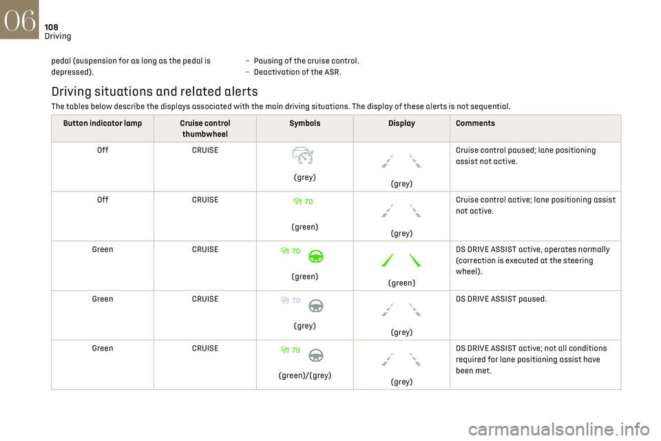
The tables below describe the displays associated with the main driving situations. The display of these alerts is not sequential.
Button indicator lamp Cruise control thumbwheelSymbols
Display Comments
Off CRUISE
(grey)
(grey)Cruise control paused; lane positioning
assist not active.
Off CRUISE
(green)
(grey)Cruise control active; lane positioning assist
not active.
Green CRUISE
(green)
(green)DS DRIVE ASSIST active, operates normally
(correction is executed at the steering
wheel).
Green CRUISE 70
(grey)
(grey)DS DRIVE ASSIST paused.
Green CRUISE
(green)/(grey)
(grey)DS DRIVE ASSIST active; not all conditions
required for lane positioning assist have
been met.
Operating limits
The Lane Keeping Assist system may
issue an alert when the vehicle is
travelling in a long straight lane on a smooth
road surface even if the driver is holding the
steering wheel properly.
Page 139 of 244

137
Practical information07
Accelerated charging
The end of charging is indicated by the charging
control unit and by the fixed lighting of the green
indicator lamp in the flap.
► Hang up the nozzle on the charging unit and
close the charging flap.
Fast charging
The end of charging is indicated by the charger
and by the fixed lighting of the green indicator
lamp in the flap.
► Hang up the nozzle on the charging station.
► Depending on version, replace the protective
cover on the base and close the charging flap.
Towing device
Load distribution
► Distribute the load in the trailer so that
the heaviest items are as close as possible to
the axle, and the nose weight approaches the
maximum permitted without exceeding it.
Air density decreases with altitude, thus reducing
engine performance. The maximum load which
can be towed must be reduced by 10% per
1,000 metres of altitude.
Use towing devices and their genuine
wiring harnesses approved by the
Manufacturer. It is recommended that the
fitting be performed by a dealer or a qualified
workshop.
If not fitted by a dealer, it must still be fitted
in accordance with the Manufacturer's
instructions.
Certain driving or manoeuvring aid functions
are automatically deactivated if an approved
towing system is used.
Observe the maximum authorised towable
weight, indicated on the vehicle's
registration certificate, the manufacturer's
label as well as in the Technical data section of
this guide.
Complying with the maximum authorised
nose weight (towball) also includes the use of
accessories (bicycle carriers, tow boxes, etc.).
Observe the legislation in force in the
country where you are driving.
Electric motor
Electric vehicles must never be equipped
with towing devices.
It is therefore not possible to tow a trailer or
caravan.
Roof bars
As a safety measure and to avoid
damaging the roof, it is essential to use
the transverse bars approved for the vehicle.
Observe the instructions on fitting and use
contained in the guide supplied with the roof
bars.
To install the roof bars, you must secure them
only to the four fixing points on the roof frame.
These points are concealed by the vehicle's doors
when they are closed.
The roof bar fixings include a lug to be fitted into
the hole at each fixing point.
Maximum load distributed over the roof
bars, for a loading height not exceeding
40 cm: 75 kg.
As this value may change, please verify the
maximum load set out in the manual supplied
with the roof bars.
Page 140 of 244

138
Practical information07
If the height exceeds 40 cm, adapt the speed
of the vehicle to the profile of the road to avoid
damaging the roof bars and the fixings on the
vehicle.
Be sure to refer to national legislation in order
to comply with the regulations for transporting
objects which are longer than the vehicle.
Recommendations
Distribute the load uniformly, taking care
to avoid overloading one of the sides.
Arrange the heaviest part of the load as close
as possible to the roof.
Secure the load firmly.
Drive gently: the vehicle will be more
susceptible to the effects of side winds and its
stability may be affected.
Regularly check the security and tight
fastening of the roof bars, at least before each
trip.
Remove the roof bars once they are no longer
needed.
Snow chains
In wintry conditions, snow chains improve
traction as well as the behaviour of the vehicle
when braking.
The snow chains must be fitted only to
the front wheels. They must never be
fitted to "space-saver" type spare wheels.
Take account of the legislation specific to
each country on the use of snow chains
and the maximum authorised speed.
Use only chains designed to be fitted to the type
of wheel fitted to the vehicle:
Original tyre size Chain type 215/65 R16 Cannot be fitted with chains
215/60 R17 Polaire XP9 with manual locking
215/55R18 Cannot be fitted with chains
For more information on snow chains, contact a
dealer or a qualified workshop.
Installation tips
► To fit the chains during a journey, stop the
vehicle on a flat surface on the side of the road.
► Apply the parking brake and position any
wheel chocks under the wheels to prevent
movement of the vehicle.
► Fit the chains following the instructions
provided by the manufacturer.
► Move off gently and drive for a few moments,
without exceeding 31 mph (50 km/h).
► Stop the vehicle and check that the snow
chains are correctly tightened.
It is strongly recommended that before
you leave, you practise fitting the snow
chains on a level and dry surface.
Avoid driving with snow chains on roads
that have been cleared of snow to avoid
damaging the vehicle's tyres and the road
surface. If the vehicle is fitted with alloy
wheels, check that no part of the chain or its
fixings is in contact with the wheel rim.
Energy economy mode
This system manages the duration of use of
certain functions, in order to conserve a sufficient
level of charge in the battery with the ignition off.
After switching off the engine, you can still
use functions such as the audio and telematic
system, the wipers and the dipped beam
headlamps or courtesy lamps, for a combined
duration of approximately 40 minutes.
Selecting the mode
A confirmation message is displayed when
energy economy mode is entered, and the active
functions are placed on standby.
If a telephone call is in progress at the
time, it will be maintained for around 10
minutes via the audio system’s hands-free
system.
Exiting the mode
These functions are automatically reactivated the
next time the vehicle is used.
To restore the use of these functions immediately,
start the engine and let it run:
– For less than 10 minutes, to use the equipment
for approximately 5 minutes.
– For more than 10 minutes, to use the equipment
for approximately 30 minutes.
Let the engine run for the specified duration to
ensure that the battery charge is sufficient.
To recharge the battery, avoid repeatedly or
continuously restarting the engine.
A flat battery prevents the engine from
starting.
For more information on the 12 V battery, refer
to the corresponding section.
Load reduction mode
This system manages the use of certain functions
according to the level of charge remaining in the
battery.
When the vehicle is being driven, the load
reduction function temporarily deactivates
certain functions, such as the air conditioning
and the heated rear screen.
The deactivated functions are reactivated
automatically as soon as conditions permit.
Page 151 of 244

149In the event of a breakdown08
Under the boot carpet
► Raise the boot carpet by pulling the strap to
access the tools.
With temporary puncture repair kit
With spare wheel
These tools are specific to the vehicle and
may vary according to the level of
equipment.
Do not use them for any other purpose.
The jack must only be used to change a
wheel with a damaged or punctured tyre.
Do not use any jack other than the one
supplied with the vehicle.
If the vehicle does not have its original jack,
contact a dealer or a qualified workshop
to obtain the one that was intended by the
manufacturer.
The jack meets European standards, as
defined in the Machinery Directive 2006/42/
CE.
The jack does not require any maintenance.
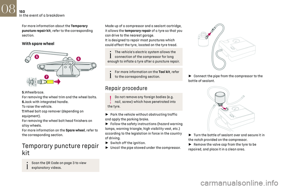
List of tools
1. Chock to immobilise the vehicle (depending on
equipment)
2. Socket for the wheel security bolts (depending
on equipment)
For adapting the wheelbrace to the special
‘security’ bolts.
3. Removable towing eye
For more information on Towing the vehicle and
using the removable towing eye, refer to the
corresponding section.
With temporary puncture repair kit
4.12 V compressor with a cartridge of sealant and
a speed limit sticker.
For temporary repair of a tyre and to adjust the
tyre pressure.
Page 152 of 244

150In the event of a breakdown08
For more information about the Temporary
puncture repair kit, refer to the corresponding
section.
With spare wheel
5.Wheelbrace.
For removing the wheel trim and the wheel bolts.
6.Jack with integrated handle.
To raise the vehicle.
7.Wheel bolt cap remover (depending on
equipment).
For removing the wheel bolt head finishers on
alloy wheels.
For more information on the Spare wheel, refer to
the corresponding section.
Temporary puncture repair
kit
Scan the QR Code on page 3 to view
explanatory videos.
Made up of a compressor and a sealant cartridge,
it allows the temporary repair of a tyre so that you
can drive to the nearest garage.
It is designed to repair most punctures which
could affect the tyre, located on the tyre tread.
The vehicle's electric system allows the
connection of the compressor for long
enough to inflate a tyre after a puncture repair.
For more information on the Tool kit, refer
to the corresponding section.
Repair procedure
Do not remove any foreign bodies (e.g.
nail, screw) which have penetrated into
the tyre.
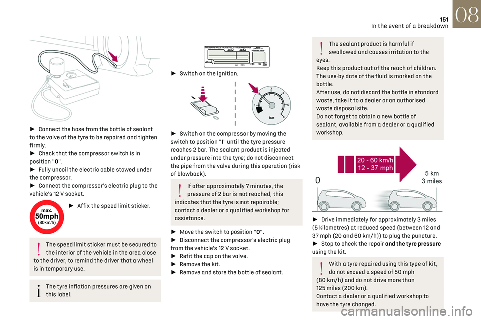
► Park the vehicle without obstructing traffic
and apply the parking brake.
► Follow the safety instructions (hazard warning
lamps, warning triangle, high visibility vest, etc.)
according to the legislation in force in the country
of driving.
► Switch off the ignition.
► Uncoil the pipe stowed under the compressor.
► Connect the pipe from the compressor to the
bottle of sealant.
► Turn the bottle of sealant over and secure it in
the notch provided on the compressor.
► Remove the valve cap from the tyre to be
repaired, and place it in a clean area.
Page 153 of 244

151In the event of a breakdown08
► Connect the hose from the bottle of sealant
to the valve of the tyre to be repaired and tighten
firmly.
► Check that the compressor switch is in
position "O".
► Fully uncoil the electric cable stowed under
the compressor.
► Connect the compressor's electric plug to the
vehicle's 12 V socket.
► Affix the speed limit sticker.
The speed limit sticker must be secured to
the interior of the vehicle in the area close
to the driver, to remind the driver that a wheel
is in temporary use.
The tyre inflation pressures are given on
this label.
► Switch on the ignition.
► Switch on the compressor by moving the
switch to position "I" until the tyre pressure
reaches 2 bar. The sealant product is injected
under pressure into the tyre; do not disconnect
the pipe from the valve during this operation (risk
of blowback).
If after approximately 7 minutes, the
pressure of 2 bar is not reached, this
indicates that the tyre is not repairable;
contact a dealer or a qualified workshop for
assistance.
► Move the switch to position "O".
► Disconnect the compressor's electric plug
from the vehicle's 12 V socket.
► Refit the cap on the valve.
► Remove the kit.
► Remove and store the bottle of sealant.
The sealant product is harmful if
swallowed and causes irritation to the
eyes.
Keep this product out of the reach of children.
The use-by date of the fluid is marked on the
bottle.
After use, do not discard the bottle in standard
waste, take it to a dealer or an authorised
waste disposal site.
Do not forget to obtain a new bottle of
sealant, available from a dealer or a qualified
workshop.
► Drive immediately for approximately 3 miles
(5 kilometres) at reduced speed (between 12 and
37 mph (20 and 60 km/h)) to plug the puncture.
► Stop to check the repair and the tyre pressure
using the kit.
With a tyre repaired using this type of kit,
do not exceed a speed of 50 mph
(80 km/h) and do not drive more than
125 miles (200 km).
Contact a dealer or a qualified workshop to
have the tyre changed.
Page 155 of 244

153In the event of a breakdown08
► Put the spare wheel back in place in its
housing.
► Slacken the nut on the bolt by a few turns.
► Position the fastening device (nut and bolt) in
the middle of the wheel.
► Tighten the central nut sufficiently to retain
the wheel correctly.
► Depending on version, put the tool box back
in place in the middle of the wheel and clip it in
place.
Removing a wheel
Parking the vehicle
Immobilise the vehicle where it does not
obstruct traffic: the ground must be level,
stable and non-slippery.
With a manual gearbox, engage first gear
to lock the wheels, apply the parking brake,
unless it is programmed to be in automatic
mode, and switch off the ignition.
With an automatic gearbox, select mode P
to lock the wheels, apply the parking brake,
unless it is programmed to be in automatic
mode, and switch off the ignition.
Check for the fixed illumination of the parking
brake indicator lamps in the instrument panel.
The occupants must get out of the vehicle and
wait where they are safe.
If necessary, place a chock under the wheel
diagonally opposite the wheel to be changed.
Never go underneath a vehicle raised using a
jack; use an axle stand.
Wheel with wheel trim
When removing the wheel, first remove
the wheel trim by pulling at the valve aperture
using the wheelbrace.
When refitting the wheel, refit the wheel trim,
starting by placing its aperture in line with the
valve and then pushing it into place all round
its edge with the palm of your hand.
► To remove the wheel bolt cover on each of the
bolts, use tool 7 (alloy wheels).
► Fit security socket 2 on wheelbrace 5 to
slacken the security bolt.
► Slacken the other bolts using the
wheelbrace 5 only.
► Place the foot of jack 6 on the ground and
ensure that it is directly below the front A or
rear B jacking point on the underbody, whichever
is closest to the wheel to be changed.