fuse box location CITROEN DS3 CROSSBACK 2023 Owners Manual
[x] Cancel search | Manufacturer: CITROEN, Model Year: 2023, Model line: DS3 CROSSBACK, Model: CITROEN DS3 CROSSBACK 2023Pages: 244, PDF Size: 7.7 MB
Page 6 of 244

4
Overview
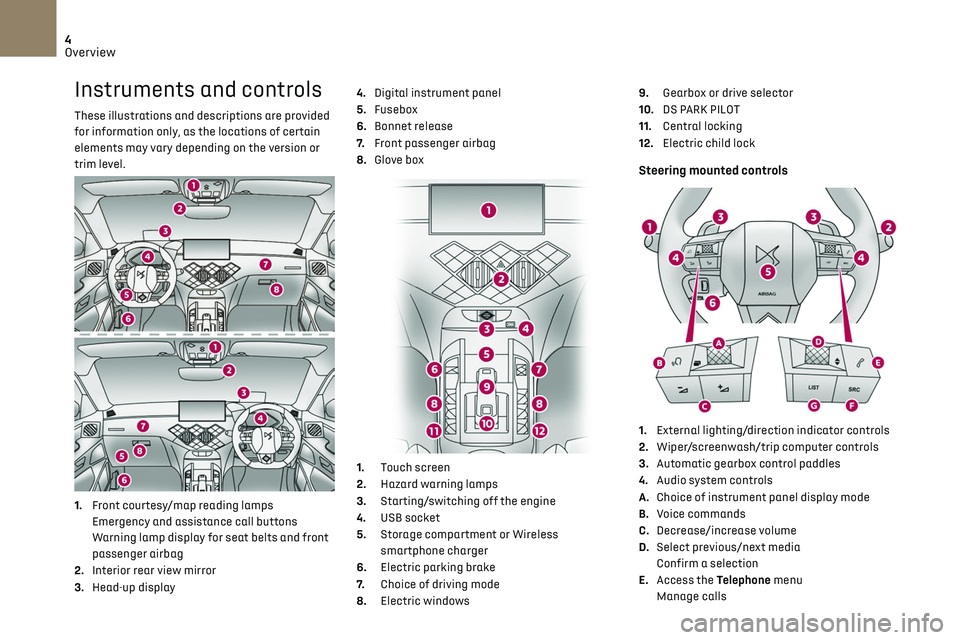
Instruments and controls
These illustrations and descriptions are provided
for information only, as the locations of certain
elements may vary depending on the version or
trim level.
1.Front courtesy/map reading lamps
Emergency and assistance call buttons
Warning lamp display for seat belts and front
passenger airbag
2. Interior rear view mirror
3. Head-up display 4.
Digital instrument panel
5. Fusebox
6. Bonnet release
7. Front passenger airbag
8. Glove box
1. Touch screen
2. Hazard warning lamps
3. Starting/switching off the engine
4. USB socket
5. Storage compartment or Wireless
smartphone charger
6. Electric parking brake
7. Choice of driving mode
8. Electric windows 9.
Gearbox or drive selector
10. DS PARK PILOT
11. Central locking
12. Electric child lock
Steering mounted controls
1.External lighting/direction indicator controls
2. Wiper/screenwash/trip computer controls
3. Automatic gearbox control paddles
4. Audio system controls
A. Choice of instrument panel display mode
B. Voice commands
C. Decrease/increase volume
D. Select previous/next media
Confirm a selection
E. Access the Telephone menu
Manage calls
Page 142 of 244

140
Practical information07
► Clip the stay in its housing.
► Lower the bonnet and release it near the end
of its travel.
► Pull on the bonnet to check that it is locked
correctly.
Because of the presence of electrical
equipment under the bonnet, it is
recommended that exposure to water (rain,
washing, etc.) be limited.
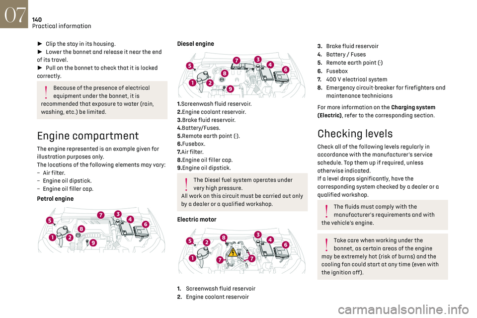
Engine compartment
The engine represented is an example given for
illustration purposes only.
The locations of the following elements may vary:
–
Air filt
er.
–
Engine oil dip
stick.
–
Engine oil filler c
ap.
Petrol engine
Diesel engine
1.Screenwash fluid reservoir.
2.Engine coolant reservoir.
3.Brake fluid reservoir.
4.Battery/Fuses.
5.Remote earth point (-).
6.Fusebox.
7. Air filter.
8.Engine oil filler cap.
9.Engine oil dipstick.
The Diesel fuel system operates under
very high pressure.
All work on this circuit must be carried out only
by a dealer or a qualified workshop.
Electric motor
1. Screenwash fluid reservoir
2. Engine coolant reservoir
3.Brake fluid reservoir
4. Battery / Fuses
5. Remote earth point (-)
6. Fusebox
7. 400 V electrical system
8. Emergency circuit-breaker for firefighters and
maintenance technicians
For more information on the Charging system
(Electric), refer to the corresponding section.
Checking levels
Check all of the following levels regularly in
accordance with the manufacturer's service
schedule. Top them up if required, unless
otherwise indicated.
If a level drops significantly, have the
corresponding system checked by a dealer or a
qualified workshop.
The fluids must comply with the
manufacturer's requirements and with
the vehicle's engine.
Take care when working under the
bonnet, as certain areas of the engine
may be extremely hot (risk of burns) and the
cooling fan could start at any time (even with
the ignition off).
Used products
Avoid prolonged contact of used oil or
fluids with the skin.
Most of these fluids are harmful to health and
very corrosive.
Do not discard used oil or fluids into
sewers or onto the ground.
Empty used oil into the containers reserved
for this purpose at a dealer or a qualified
workshop.
Engine oil
The level is checked, with the engine
having been switched off for at least 30
minutes and on level ground, using the dipstick.
It is normal to top up the oil level between two
services (or oil changes). It is recommended that
you check the level, and top up if necessary, every
3,000 miles (5,000 km).
In order to maintain the reliability of the
engine and emissions control system,
never use additives in the engine oil.
Checking using the dipstick
For the location of the dipstick, please refer
to the illustration of the corresponding engine
compartment.
► Grasp the dipstick by its coloured grip and pull
it out completely.
Page 161 of 244

159In the event of a breakdown08
► Change the bulb.
Changing a fuse
Accessing the tools
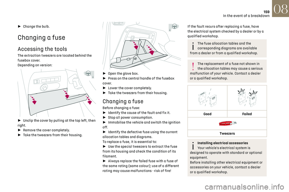
The extraction tweezers are located behind the
fusebox cover.
Depending on version:
► Unclip the cover by pulling at the top left, then
right.
► Remove the cover completely.
► Take the tweezers from their housing.
► Open the glove box.
► Press on the central handle of the fusebox
cover.
► Lower the cover completely.
► Take the tweezers from their housing.
Changing a fuse
Before changing a fuse:
► Identify the cause of the fault and fix it.
► Stop all power consumption.
► Immobilise the vehicle and switch the ignition
off.
► Identify the defective fuse using the current
allocation tables and diagrams.
To replace a fuse, it is essential to:
► Use the special tweezers to extract the fuse
from its housing and check the condition of its
filament.
► Always replace the failed fuse with a fuse of
the same rating (same colour); use of a different
rating may cause malfunctions - risk of fire!
If the fault recurs after replacing a fuse, have
the electrical system checked by a dealer or by a
qualified workshop.
The fuse allocation tables and the
corresponding diagrams are available
from a dealer or from a qualified workshop.
The replacement of a fuse not shown in
the allocation tables may cause a serious
malfunction of your vehicle. Contact a dealer
or a qualified workshop.
Good
Failed
Tweezers
Installing electrical accessories
Your vehicle's electrical system is
designed to operate with standard or optional
equipment.
Before installing other electrical equipment or
accessories on your vehicle, contact a dealer
or a qualified workshop.