CITROEN DS7 CROSSBACK 2022 Owners Manual
Manufacturer: CITROEN, Model Year: 2022, Model line: DS7 CROSSBACK, Model: CITROEN DS7 CROSSBACK 2022Pages: 244, PDF Size: 6.87 MB
Page 141 of 244
139
Driving06
The parking sensors supplement the information
in the view from above the vehicle.
Different contextual views are available:
–
Aut
omatic zoom view.
–
St
andard view.
–
Panoramic vie
w.
Depending on the context, the system chooses
the best view to display (standard or automatic
zoom).
The view type can be changed at any time during
the manoeuvre.
The system status is not saved when the ignition
is switched off.
Operating principle
Using the camera, the vehicle's close
surroundings are recorded during low speed
manoeuvres.
An image from above the vehicle in its close
surroundings is created in real time (on the side of
the screen), as the vehicle progresses.
This view makes it easier to align the vehicle
when parking and to perceive nearby obstacles. It is automatically deleted if the vehicle remains
stationary for too long.
Settings
In the side menu, this menu allows you to
carry out the following operations:
–
adjust the v
olume of the audible signal.
–
adjust the brigh
tness.
–
adjust the c
ontrast.
Activation/Deactivation
To activate the camera, engage reverse gear.
The system is deactivated:
–
when changing out o
f reverse gear.
–
b
y pressing the cross in the top left-hand corner
of the touch screen.
Automatic zoom view
The rear camera records the vehicle's
surroundings during the manoeuvre in order to
create a view from above the rear of the vehicle in
its close surroundings, allowing the vehicle to be
manoeuvred around nearby obstacles.
Using the sensors located on the rear bumper,
the automatic zoom view is displayed when
approaching an obstacle at the red line (less than
30 cm) during the manoeuvre.
This view is only available automatically.
Obstacles may appear further away than
they actually are.
It is important to monitor the sides of the
vehicle during the manoeuvre, using the
mirrors.
Parking sensors also provide additional
information about the area around the vehicle.
Standard view
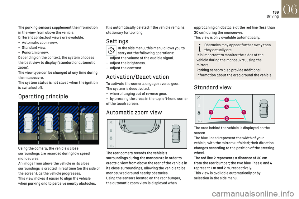
The area behind the vehicle is displayed on the
screen.
The blue lines 1 represent the width of your
vehicle, with the mirrors unfolded; their direction
changes according to the position of the steering
wheel.
The red line 2 represents a distance of 30 cm
from the rear bumper; the two blue lines 3 and 4
represent 1 m and 2 m, respectively.
This view is available automatically or by
selection in the side menu.
Page 142 of 244

140
Driving06
Panoramic view
The panoramic view allows you to leave, in
reverse, a parking space by anticipating the
arrival of vehicles, pedestrians or cyclists.
This view is not recommended for carrying out a
complete manoeuvre.
This view is only available by selection in the side
menu.
360 Vision
For more information, refer to the General
recommendations on the use of driving
and manoeuvring aids.
This system allows you to view your vehicle's
close surroundings on the touch screen using
cameras, located at the front and rear of the
vehicle.
The screen is divided into 4 parts with two side
menus, a contextual view and a view from above
the vehicle in its close surroundings.
The parking sensors supplement the information
in the view from above the vehicle.
Depending on the view angle chosen in the left-
hand side menu, the system provides specific
visual assistance in particular driving conditions,
such as entering a blind intersection or
manoeuvring in areas with reduced visibility.
Different contextual views are available for the
rear or for the front:
–
Aut
omatic zoom view.
–
St
andard view.
–
Panoramic vie
w.
Depending on the context, the system chooses
the best view to display (standard or automatic
zoom).
The view type can be changed at any time during
the manoeuvre.
The system status is not saved when the ignition
is switched off.
Operating principle
Reconstructed view
The cameras are activated and a reconstruction
of a view from above your vehicle in its close
surroundings is displayed on the touch screen.
Live view
The front and rear views automatically appear in
the view from above the vehicle.
It is also possible to display any live view by
selecting the corresponding zone.
The front view can be selected in forward gear up
to 10 mph (16 km/h).
Installing the very cold climate screen can
alter the image transmitted by the front
camera.
Settings
In the side menu, this menu allows you to
carry out the following operations:
–
adjust the v
olume of the audible signal.
–
adjust the brigh
tness.
–
adjust the c
ontrast.
Page 143 of 244

141
Driving06
Activation/Deactivation
Automatic
With the rear camera, engine running and vehicle
stationary, rear vision is displayed automatically
if reverse gear is engaged.
With the front camera, engine running and speed
below 10 mph (16 km/h), rear vision is displayed
automatically if a gear is engaged.
Manual
► In the ADAS touch screen application,
select Functions>Panoramic Camera
The system is deactivated:
–
aut
omatically for the rear, when changing out
of reverse gear.
–
aut
omatically for the front, above
approximately 10 mph (16 km/h).
–
b
y pressing the cross in the top left-hand corner
of the touch screen.
Automatic zoom view
The front or rear camera records the surroundings
during the manoeuvre to create a front or
rear view from above the vehicle in its close
surroundings, making it possible to manoeuvre
the vehicle around the surrounding obstacles.
Using the sensors located on the front or
rear bumper, the automatic zoom view is
displayed when approaching an obstacle at the
red line (less than 30 cm) during the manoeuvre.
This view is only available automatically.
Depending on version, it can be activated/
deactivated in the ADAS application of the touch
screen.
Obstacles may appear further away than
they actually are.
It is important to monitor the sides of the
vehicle during the manoeuvre, using the
mirrors.
Parking sensors also provide additional
information about the area around the vehicle.
Standard view
Depending on the context, the area behind or in
front of your vehicle is displayed on the screen.
The blue lines (at the rear)/orange lines (at the
front) 1 represent the width of your vehicle, with
the mirrors unfolded; their direction changes
according to the position of the steering wheel.
The red line 2 represents a distance of 30 cm from
the rear or front bumper; the two blue lines (at the rear)/orange lines (at the front) 3 and 4 represent
1 m and 2 m respectively.
This view is available automatically or by
selection in the left-hand side menu.
Panoramic view
The rear or front panoramic view allows you to
leave a parking space by anticipating the arrival
of vehicles, pedestrians or cyclists.
This view is not recommended for carrying out a
complete manoeuvre.
This view is only available by selection in the left-
hand side menu.
Page 144 of 244

TAILOR-MADE
LUBRICANTS
FOR HAUTE
COUTURE CARS
* 1L & 5L produced in Europe
Partner\f \fince the brand’\f creation in \b015, DS automobile\f &
TotalEnergie\f \fhare common value\f : excellence, performance and
know-how. TotalEnergie\f equip\f DS vehicle\f with Quartz lubricant\f
from their fir\ft filling in the factory to approved maintenance
network\f to guarantee them optimal performance on a daily ba\fi\f.
Tailor-made for DS vehicle\f, Quartz lubricant\f make them even more
efficient, more fuel efficient and more environmentally friendly.
TotalEnergie\f and DS, official partner\f in\t automotive excellence !
Keep your engine younger for longer \
!
Quartz Ineo Xtra Fir\ft 0W-\b0 i\f a very high performance lubricant
re\fulting from the joint work of the DS Automobile\f and
TotalEnergie\f R&D team\f. It\f innovative technology extend\f your
engine’\f life while reaching \fignificant fuel \faving\f and thu\f
limiting CO
\b emi\f\fion\f. The product i\f now available in new
packaging* made of 50% recycled material and 100% rec\tyclable.
Page 145 of 244

143
Practical information07
TAILOR-MADE
LUBRICANTS
FOR HAUTE
COUTURE CARS
* 1L & 5L produced in Europe
Partner\f \fince the brand’\f creation in \b015, DS automobile\f &
TotalEnergie\f \fhare common value\f : excellence, performance and
know-how. TotalEnergie\f equip\f DS vehicle\f with Quartz lubricant\f
from their fir\ft filling in the factory to approved maintenance
network\f to guarantee them optimal performance on a daily ba\fi\f.
Tailor-made for DS vehicle\f, Quartz lubricant\f make them even more
efficient, more fuel efficient and more environmentally friendly.
TotalEnergie\f and DS, official partner\f in\t automotive excellence !
Keep your engine younger for longer \
!
Quartz Ineo Xtra Fir\ft 0W-\b0 i\f a very high performance lubricant
re\fulting from the joint work of the DS Automobile\f and
TotalEnergie\f R&D team\f. It\f innovative technology extend\f your
engine’\f life while reaching \fignificant fuel \faving\f and thu\f
limiting CO
\b emi\f\fion\f. The product i\f now available in new
packaging* made of 50% recycled material and 100% rec\tyclable.
Compatibility of fuels
Petrol fuels conforming to the EN228 standard
containing up to 5% and 10% ethanol respectively.
Diesel fuels conforming to the EN590, EN16734
and EN16709 standards and containing up to
7%, 10%, 20% and 30% fatty acid methyl ester
respectively. The use of B20 or B30 fuels, even
occasionally, imposes special maintenance
conditions referred to as "Arduous conditions".
Paraffinic Diesel fuel conforming to the EN15940
standard.
The use of any other type of (bio)fuel
(e.g. pure or diluted vegetable or animal
oils, domestic fuel) is strictly prohibited - risk
of damaging the engine and fuel system!
The only fuel additives authorised for use
are those that meet the B715001 (petrol)
or B715000 (Diesel) standards.
Diesel at low temperature
At temperatures below 0 °C (+32 °F), the
formation of paraffins in summer-type Diesel
fuels could prevent the engine from operating correctly. In these temperature conditions, use
winter-type Diesel fuel and keep the fuel tank
more than 50 % full.
At temperatures below -15 °C (+5 °F) to avoid
problems starting, it is best to park the vehicle
under shelter (heated garage).
Travelling abroad
Certain fuels could damage your vehicle’s engine.
In certain countries, the use of a particular fuel
may be required (specific octane rating, specific
trade name, etc.) to ensure correct operation of
the engine.
For all additional information, consult a dealer.
Refuelling
Fuel tank capacity: approximately 55
litres (Diesel), 62 litres (Petrol) or 43 litres
(Rechargeable hybrid).
Reserve level: approximately 6 litres.
Low fuel level
When the low fuel level is reached, this
warning lamp lights up on the instrument
panel, accompanied by the display of a message
and an audible signal. When it first comes on,
about 6 litres of fuel remain.
Until sufficient fuel is added, this warning lamp
appears every time the ignition is switched on,
accompanied by the message and the audible
signal. When driving, this message and audible
signal are repeated with increasing frequency as
the fuel level drops towards 0.
You must refuel as soon as possible to avoid
running out of fuel.
For more information on Running out of fuel
(Diesel), refer to the corresponding section.
A small arrow by the warning lamp
indicates which side of the vehicle the
fuel filler flap is located on.
Stop & Start
Never refuel with the engine in STOP
mode; you must switch off the ignition.
Refuelling
Any addition of fuel must be in quantities of at
least 10 litres, in order to be registered by the fuel
gauge.
Opening the filler flap may create a noise caused
by an inrush of air. This vacuum is entirely normal,
resulting from the sealing of the fuel system.
To refuel in complete safety:
► Always switch off the engine.
Page 146 of 244
144
Practical information07
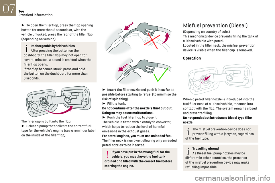
► To open the filler flap, press the flap opening
button for more than 2 seconds or, with the
vehicle unlocked, press the rear of the filler flap
(depending on version).
Rechargeable hybrid vehicles
After pressing the button on the
dashboard, the filler flap may not open for
several minutes. A sound is emitted when the
filler flap opens.
If the flap becomes stuck, press and hold
the button on the dashboard for more than
3 seconds.
The filler cap is built into the flap.
► Select a pump that delivers the correct fuel
type for the vehicle's engine (see a reminder label
on the inside of the filler flap).
► Insert the filler nozzle and push it in as far as
possible before starting to refuel (to minimise the
risk of splashing).
► Fill the tank.
Do not continue after the nozzle’s third cut-out.
Doing so may cause malfunctions.
► Push the fuel filler flap to close it.
The vehicle is fitted with a catalytic converter,
which helps to reduce the level of harmful
emissions in the exhaust gases.
For petrol engines, you must use unleaded fuel.
The filler neck is narrower, allowing only unleaded
petrol nozzles to be inserted.
If you have put in the wrong fuel for the
vehicle, you must have the fuel tank
drained and filled with the correct fuel before
starting the engine.
Misfuel prevention (Diesel)
(Depending on country of sale.)
This mechanical device prevents filling the tank of
a Diesel vehicle with petrol.
Located in the filler neck, the misfuel prevention
device is visible when the filler cap is removed.
Operation
When a petrol filler nozzle is introduced into the
fuel filler neck of a Diesel vehicle, it comes into
contact with the flap. The system remains closed
and prevents filling.
Do not persist but introduce a Diesel type filler
nozzle.
The misfuel prevention device does not
prevent filling with a jerrycan, regardless
of the fuel type.
Travelling abroad
As Diesel fuel pump nozzles may be
different in other countries, the presence
of the misfuel prevention device may make
refuelling impossible.
Page 147 of 244
145
Practical information07
Before travelling abroad, it is advisable to
check with a dealer if the vehicle is suitable
for the distribution equipment of the countries
visited.
Rechargeable hybrid
system
Electrical system
The electrical circuit of the rechargeable hybrid
system is identified by orange cables and its
components are marked with this symbol:
The rechargeable hybrid powertrain uses
a voltage of between 240 V and 400 V.
This system may be hot both when the ignition
is on and after switching it off.
Comply with the warning messages shown on
the labels, particularly inside the charging flap.
High voltage system voltage is dangerous
and can cause burns or other injuries or
even fatal electric shock.
Since damage to high voltage components is
not visible, the Manufacturer recommends
that you:
–
Ne
ver touch the components, damaged
or not, and never let your jewelry or other
metallic objects come into contact with these
components.
–
Ne
ver work on the orange high voltage
cables or on any other high voltage component
marked with the Electric risk label. Any
intervention on the high voltage system
must be carried out by qualified persons in
workshops qualified and approved to carry out
this type of work.
–
Ne
ver damage, modify or remove the orange
high voltage cables or disconnect them from
the high voltage network.
–
Ne
ver open, modify or remove the cover of
the traction battery.
–
Ne
ver work with cutting and forming tools
or heat sources near high voltage components
and cables.
In case of low level of fluid in the cooling
tank, the refilling shall only be performed in a
qualified and trained workshop to verify that
the leakage is not in the traction battery.
Any intervention on the high voltage system
must be carried out by qualified persons in
workshops qualified and approved to carry out
this type of work.Damage to the vehicle or the traction battery
could result in the leakage of toxic gases
or fluids either immediately or later. The
Manufacturer recommends that you:
–
Alw
ays inform the fire and emergency
services in the event of an incident, warning
that the vehicle is equipped with a traction
battery.
–
Ne
ver touch the liquids leaking from the
traction battery.
–
Do no
t inhale the gases emitted by the
traction battery which are toxic.
–
Mo
ve away from the vehicle in the event of
incident or accident, the gases emitted being
flammable and could cause a fire.
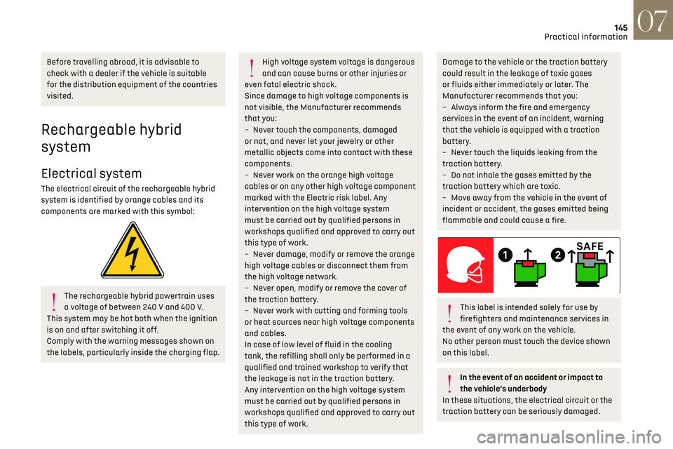
This label is intended solely for use by
firefighters and maintenance services in
the event of any work on the vehicle.
No other person must touch the device shown
on this label.
In the event of an accident or impact to
the vehicle’s underbody
In these situations, the electrical circuit or the
traction battery can be seriously damaged.
Page 148 of 244
146
Practical information07
Stop as soon as it is safe to do so and switch
off the ignition.
Contact a dealer or a qualified workshop.
When washing
Before washing the vehicle, always check
that the charging flap is closed correctly.
Never wash the vehicle while the battery is on
charge.
High-pressure washing
To avoid damaging the electrical
components, it is expressly prohibited to
use high-pressure washing in the engine
compartment or under the body.
Do not use a pressure greater than 80 bar
when washing the bodywork.
Never allow water or dust to enter the
connector or charging nozzle - risk of
electrocution or fire!
Never connect / disconnect the charging
nozzle or cable with wet hands - risk of
electrocution!
Traction battery
The Li-ion (Lithium-ion) traction battery stores the
electrical energy needed to propel the vehicle.
It is located under the rear seats.
The traction battery's range varies depending
on the type of driving, the route, the use of
thermal comfort equipment and the ageing of its
components.
The traction battery ageing depends on
several factors, such as climatic
conditions and the distance travelled.
To preserve the mileage of your vehicle
and the durability of your traction battery,
the Manufacturer recommends that you:
–
Do no
t fully charge the battery of your
electric vehicle daily (charge the traction
battery below 80% as often as possible).
–
Do no
t completely discharge the battery.
–
Do no
t store the vehicle for a long period
of non-use (more than 12 hours) when the
traction battery has a low or high charge level.
Prefer a charge level between 20 and 40%.
–
Limit the use o
f fast charging.
–
Do no
t expose the vehicle to temperatures
below -30°C and above +60°C for more than
24 hours.
–
A
void charging the vehicle at negative
temperatures (except if the vehicle ran more
than 20 minutes) or above +30°C.
–
Do no
t use the vehicle's traction battery as a
generator of energy.
–
Do no
t use a generator to recharge your
vehicle's traction battery.
In the event of damage to the traction
battery
It is strictly prohibited to work on the vehicle
yourself.
Do not touch liquids coming from the battery,
and in the event of skin contact with these
products, wash abundantly with water and
contact a doctor as soon as possible.
Contact a dealer or a qualified workshop to
have the system checked.
Disposal of the traction battery
The traction battery is designed for the life
of the vehicle if the recommendations of the
Manufacturer are followed.
If it becomes necessary to replace the battery,
contact the dealer for instructions on its disposal.
Improper disposal carries the risk of severe burns,
electric shock, and damage to the environment.
In accordance with regulations, the Manufacturer
ensures a second life or recycling of this
component in collaboration with qualified
operators.
Charging flap
The charging flap is located on the rear left-hand
side of the vehicle.
Page 149 of 244

147
Practical information07
1. Deferred charging activation button
2. Indicator lamp confirming that the nozzle is
locked into the charging connector.
Fixed red: nozzle correctly positioned and
locked.
Flashing red: nozzle incorrectly positioned or
locking not possible.
3. Charging connector
4. Light guides
Status of light
guides Meaning
Fixed white Welcome lighting when flap is opened
Status of light
guidesMeaning
Fixed blue Deferred charging
Flashing green Charging
Fixed green Charging complete
Fixed red Malfunction
In case of impact, even light, against the
charging flap, do not use it.
Do not dismantle or modify the charging
connector - risk of electrocution and/or fire!
Contact a dealer or a qualified workshop.
Charging cables, sockets and
chargers
The traction battery can be charged using several
different types of cables.
The charging cables supplied with the vehicle
are compatible with the electrical installations of
the country of sale. If you are travelling abroad,
refer to the following tables to check the
compatibility of local electrical installations with
the charging cables.
Contact a dealer or a qualified workshop to obtain
the appropriate charging cable(s).
Identification labels on charging sockets/
connectors
Identification labels are affixed to the vehicle,
charging cable and charger to inform the user
about which device needs to be used.
Page 150 of 244
148
Practical information07
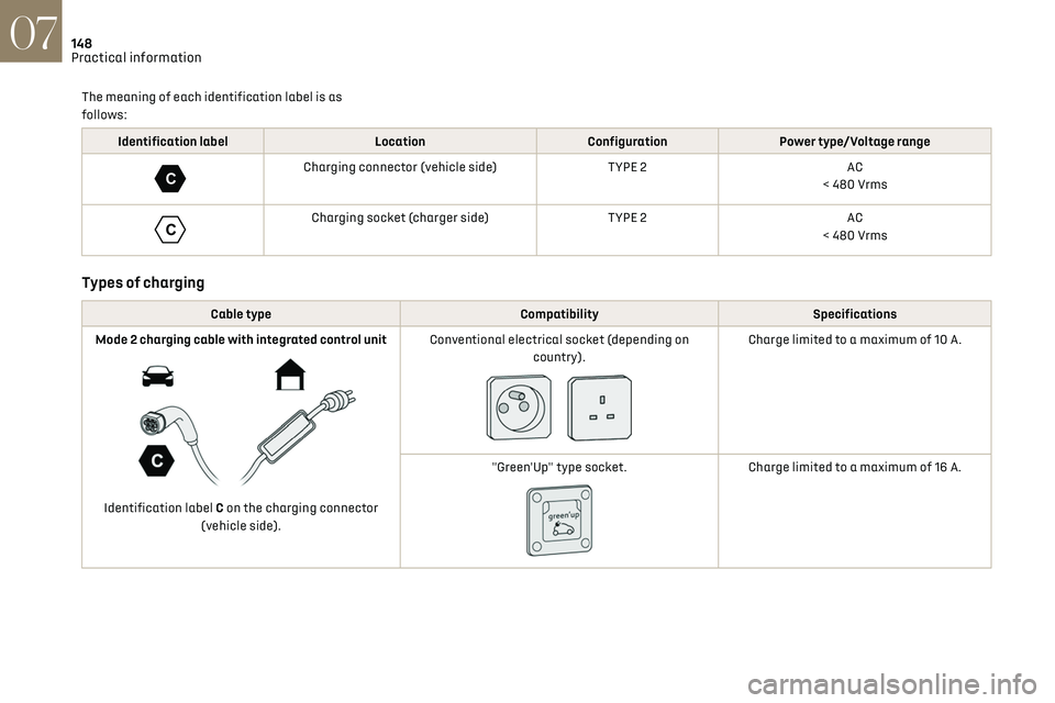
The meaning of each identification label is as
follows:
Identification labelLocationConfigurationPower type/Voltage range
C
Charging connector (vehicle side) TYPE 2AC
< 480 Vrms
C
Charging socket (charger side) TYPE 2AC
< 480 Vrms
Types of charging
Cable type CompatibilitySpecifications
Mode 2 charging cable with integrated control unit
Identification label C on the charging connector (vehicle side). Conventional electrical socket (depending on
country).
Charge limited to a maximum of 10 A.
"Green'Up" type socket.
Charge limited to a maximum of 16 A.