spare wheel Citroen GRAND C4 PICASSO RHD 2016 2.G Owner's Manual
[x] Cancel search | Manufacturer: CITROEN, Model Year: 2016, Model line: GRAND C4 PICASSO RHD, Model: Citroen GRAND C4 PICASSO RHD 2016 2.GPages: 523, PDF Size: 13.63 MB
Page 5 of 523
Hazard warning lamps 222
Horn
2
22
Emergency
or assistance call
2
22
Electronic stability
control
(ESC)
2
23
Seat
bel
ts
2
26
Airbags
2
31
Child
seats
2
36
Deactivating
t
he
p
assenger's
f
ront airbag
2
38
ISOFIX
mountings
2
47
Child
lock
2
54
Safety
Fuel 2 55
Misfuel prevention (Diesel)
2
56
Snow
chains
2
58
Very
cold climate screen(s)
2
59
Towbar
with quickly detachable
towball
2
60
Towing
a trailer
2
62
Energy
economy mode
2
63
Accessories
2
64
Changing
a wiper blade
2
66
Roof
bars
2
67
Bonnet
26
9
Petrol
engines
2
70
Diesel
engines
2
71
Checking
levels
2
72
Checks
2
75
AdBlue
® additive and SCR system
(
BlueHDi Diesel) 2 77
Practical information
Warning triangle 2 81
Temporary
pu
ncture
r
epair kit
2
82
Spare
wheel
2
89
Changing
a bulb
2
99
Changing
a fuse
3
08
12
V battery
3
13
To w i n g
3
17
Running
out of fuel (Diesel)
3
19
In the event o f a b reakdown
Petrol engines 3 20
Petrol weights
3
22
Diesel
engines
3
24
Diesel
weights
3
26
Dimensions
3
28
Identification
ma
rkings
3
29
Technical data
Emergency or assistance 3 30Audio and telematics
Mirrors 2 01
Lighting control stalk
2
04
Automatic
illumination of headlamps
2
09
Automatic
headlamp dipping
2
10
Daytime
running lamps
2
12
Direction
indicators
2
13
Adjusting
the headlamp beam height
2
13
Directional
l
ighting
2
15
Wiper
control stalk
2
16
Screenwash
2
18
Automatic
rain sensitive wipers
2
19
Panoramic
sunroof
2
21
Lighting and v isibility
Alphabetical
in
dex
For the audio and touch screen telematic systems, refer to the
s
upplement to the handbook or go to
t
he following internet address:
http://service.citroen.com/ddb/
Contents
Page 12 of 523
10
Limit the causes of excess consumption
Spread loads throughout the vehicle; place the heaviest items in the bottom of the boot, as close as possible to the rear seats.
Limit
the loads carried in the vehicle and reduce wind resistance (roof
b
ars, roof rack, bicycle carrier, trailer...). Use a roof box in preference.
Remove
roof bars and roof racks after use.
At
the end of winter, remove snow tyres and refit your summer tyres.
Observe the recommendations
on maintenance
Check the tyre pressures regularly, when cold, referring to the label in the door aperture, driver's side.
Carry
out this check in particular:
-
b
efore a long journey,
-
a
t each change of season,
-
a
fter a long period out of use.
Don't
forget the spare wheel and the tyres on any trailer or caravan.
Have
your vehicle serviced regularly (engine oil, oil filter, air filter,
p
assenger compartment filter...) and observe the schedule of
o
perations recommended in the manufacturer's service schedule.
With
a BlueHDi Diesel engine, if the SCR system is faulty your vehicle
b
ecomes polluting; go to a CITROËN dealer or a qualified workshop
w
ithout delay to have the emissions of nitrogen oxides brought back to
t
he legal level.
When
refuelling, do not continue after the third cut-off of the nozzle to
a
void any over flow.
At
the wheel of your new vehicle, it is only after the first 1 800 miles
(
3 000 kilometres) that you will see the fuel consumption settle down to
a
consistent average.
Eco-driving
Page 71 of 523
69
Operating faults
If several foot movements below the rear bumper fail to open the tailgate, wait a
f
ew seconds before starting again.
The
function is automatically deactivated in the
e
vent of heavy rain or accumulation of snow.
If
the function fails to operate, check
t
hat the electronic key is not exposed to
s
trong electromagnetic inter ference (a
s
mar tphone, ...).
The
function may not work correctly with a
pro
sthetic
le
g.
The
function may not work correctly if your
v
ehicle is fitted with a towbar. In
some circumstances, the tailgate may only o
pen or close, particularly if:
-
y
our vehicle is fitted with a towbar,
-
y
ou hitch or unhitch a trailer,
-
y
ou fit or remove a bicycle carrier,
-
y
ou load or unload bicycles from a bicycle
c
a r r i e r,
-
y
ou place or lift something behind the
v
ehicle,
-
a
n animal approaches the bumper,
-
y
ou are washing your vehicle,
-
a
service is being carried out on your
v
ehicle,
-
y
ou are accessing the spare wheel
(
depending
o
n
v
ersion).
To
avoid such operating problems, keep the
e
lectronic key away from the recognition zone
o
r deactivate "Hands-Free Tailgate Access".
Ensure
that no object or person might prevent
t
he correct opening or closing of the tailgate.
Be
particularly aware of children when
o
perating the tailgate.
2
Access
Page 180 of 523
178
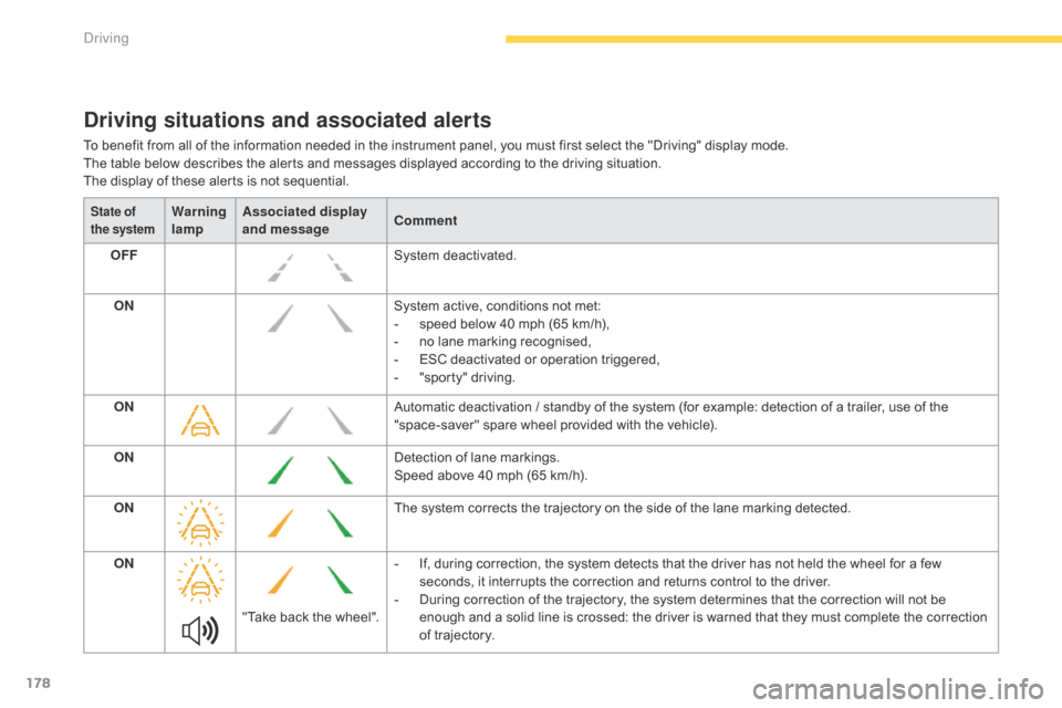
Driving situations and associated alerts
To benefit from all of the information needed in the instrument panel, you must first select the "Driving" display mode.
T he table below describes the alerts and messages displayed according to the driving situation.
The
display of these alerts is not sequential.
State of
the systemWarning
lamp Associated display
and message
Comment
OFF System
d
eactivated.
ON System
active, conditions not met:
-
s
peed below 40 mph (65 km/h),
-
n
o lane marking recognised,
-
ES
C deactivated or operation triggered,
-
"
sporty" driving.
ON Automatic
deactivation / standby of the system (for example: detection of a trailer, use of the
"
space-saver" spare wheel provided with the vehicle).
ON Detection
of lane markings.
Speed
above 40 mph (65 km/h).
ON The
system corrects the trajectory on the side of the lane marking detected.
ON "Take
back the wheel".-
I
f, during correction, the system detects that the driver has not held the wheel for a few
s
econds, it interrupts the correction and returns control to the driver.
-
D
uring correction of the trajectory, the system determines that the correction will not be
e
nough and a solid line is crossed: the driver is warned that they must complete the correction
o
f trajectory.
Driving
Page 201 of 523
199
Under-inflation alertReinitialisation
This is given by fixed illumination of t
his warning lamp, accompanied by
a
n audible signal and, depending on
e
quipment, the display of a message. It
is necessary to reinitialise the system every t
ime one or more tyre pressures are adjusted,
a
nd after changing one or more wheels.
F
R
educe speed immediately, avoid
e
xcessive steering movements and sudden
b
raking.
F
S
top the vehicle as soon as it is safe
to
do
so. F
I n the event of a puncture, use the
temporary
puncture repair kit or the spare
w
heel (depending on equipment),
or
F
i
f you have a compressor, such as the one
i
n the temporary puncture repair kit, check
t
he pressures of the four tyres when cold,
or
F
i
f it is not possible to make this check
i
mmediately, drive carefully at reduced
s
peed.
The
loss of pressure detected does not
a
lways cause visible bulging of the tyre.
D
o
not satisfy yourself with just a visual
c
heck. The
alert is maintained until the system
i
s
r
einitialised.
Snow chains
The system does not have to be reinitialised after fitting or removing
sn
ow
c
hains.
Before
reinitialising the system, ensure
t
hat the pressures of the four tyres are
correct for the use of the vehicle and in
l
ine with the recommendations on the
t
yre pressure label.
The under-inflation alert can only
b
e relied on if the reinitialisation of
t
he system has been done with the
p
ressures in the four tyres correctly
adjusted.
The under-inflation detection system
d
oes not give a warning if a pressure is
i
ncorrect at the time of reinitialisation.
4
Driving
Page 260 of 523
258
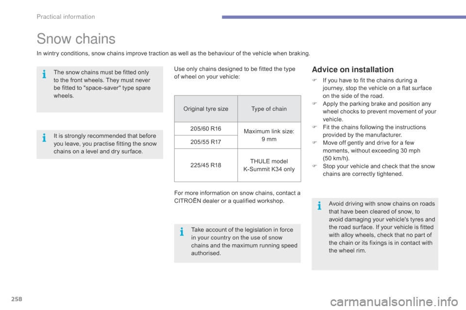
Original tyre sizeT ype of chain
205/60 R16 Maximum
link size:
9
mm
205/55
R17
225/45
R18 THULE
model
K
-Summit K34 only
For
more information on snow chains, contact a
C
ITROËN dealer or a qualified workshop.
Use
only chains designed to be fitted the type
o
f
wheel on your vehicle:
Snow chains
In wintry conditions, snow chains improve traction as well as the behaviour of the vehicle when braking.
T he snow chains must be fitted only
t
o the front wheels. They must never
b
e fitted to "space-saver" type spare
w
heels.
Advice on installation
F If you have to fit the chains during a j
ourney, stop the vehicle on a flat sur face
o
n the side of the road.
F
A
pply the parking brake and position any
w
heel chocks to prevent movement of your
v
ehicle.
F
F
it the chains following the instructions
p
rovided by the manufacturer.
F
M
ove off gently and drive for a few
m
oments, without exceeding 30 mph
(
50 km/h).
F
S
top your vehicle and check that the snow
c
hains are correctly tightened.
Take
account
of
the
legislation
in
force
i
n your country on the use of snow
chains
and
the
maximum
running
speed
a
uthorised. Avoid
driving with snow chains on roads
t
hat have been cleared of snow, to
a
void damaging your vehicle's tyres and
t
he road sur face. If your vehicle is fitted
w
ith alloy wheels, check that no part of
t
he chain or its fixings is in contact with
t
he wheel rim.
It
is
strongly
recommended
that
before
y
ou
leave,
you
practise
fitting
the
snow
c
hains
on
a
level
and
dry
sur face.
Practical information
Page 291 of 523
289
Spare wheel
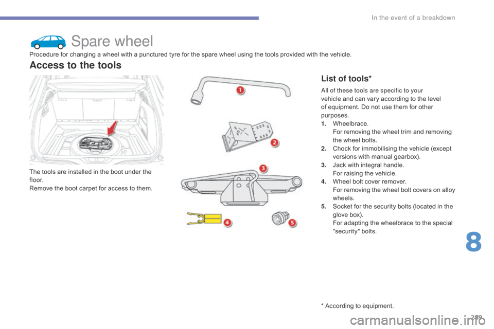
The tools are installed in the boot under the fl o o r.
Remove
the boot carpet for access to them.
Access to the tools
List of tools*
Procedure for changing a wheel with a punctured tyre for the spare wheel using the tools provided with the vehicle.
A ll of these tools are specific to your
vehicle
and can vary according to the level
o
f equipment. Do not use them for other
p
urposes.
1.
W
heelbrace.
F
or removing the wheel trim and removing
t
he wheel bolts.
2.
C
hock for immobilising the vehicle (except
v
ersions with manual gearbox).
3.
J
ack with integral handle.
F
or raising the vehicle.
4.
W
heel bolt cover remover.
F
or removing the wheel bolt covers on alloy
w
heels.
5.
S
ocket for the security bolts (located in the
g
love box).
F
or adapting the wheelbrace to the special
"s
ecurity"
b
olts.
*
According to equipment.
8
In the event of a breakdown
Page 292 of 523
290
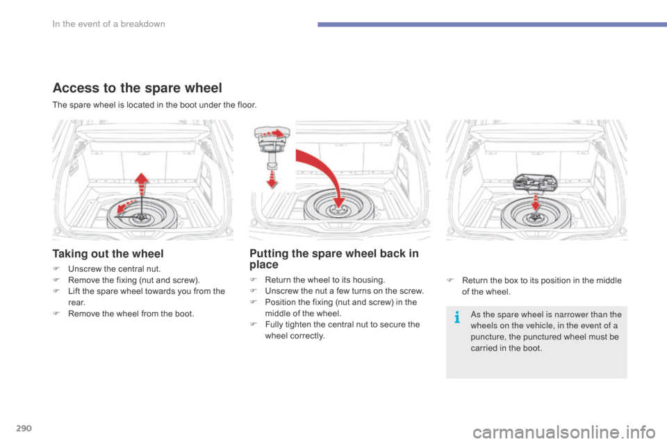
Taking out the wheel
F Unscrew the central nut.
F R emove the fixing (nut and screw).
F
L
ift the spare wheel towards you from the
r
e a r.
F
R
emove the wheel from the boot. As the spare wheel is narrower than the
wheels on the vehicle, in the event of a
puncture,
the punctured wheel must be
c
arried in the boot.
The
spare wheel is located in the boot under the floor.
Access to the spare wheel
Putting the spare wheel back in
place
F Return
the wheel to its housing.
F U nscrew the nut a few turns on the screw.
F
P
osition the fixing (nut and screw) in the
m
iddle of the wheel.
F
F
ully tighten the central nut to secure the
w
heel correctly. F
R eturn the box to its position in the middle
o
f the wheel.
In the event of a breakdown
Page 293 of 523
291
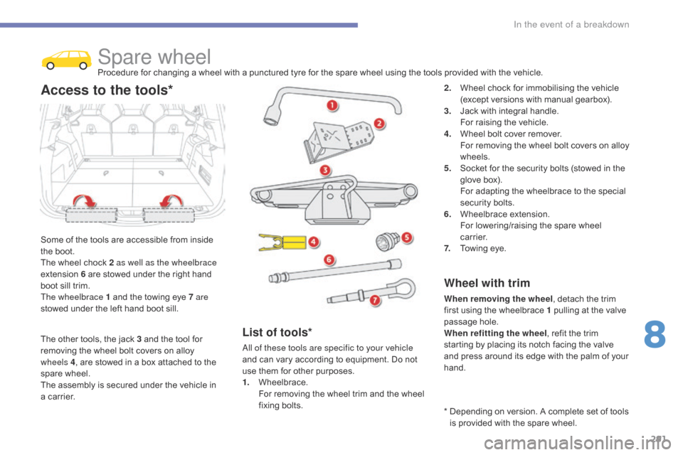
Spare wheelProcedure for changing a wheel with a punctured tyre for the spare wheel using the tools provided with the vehicle.
S
ome
of
the
tools are accessible from inside
t
he
boot.
The
wheel
chock 2 as well as the wheelbrace
extension
6
are stowed under the right hand
b
oot
sill
trim.
The wheelbrace 1
and the towing eye 7 are
stowed
under
the left hand boot sill.
Access to the tools*2. Wheel chock for immobilising the vehicle (
except versions with manual gearbox).
3.
J
ack with integral handle.
F
or raising the vehicle.
4.
W
heel bolt cover remover.
F
or removing the wheel bolt covers on alloy
w
heels.
5.
S
ocket for the security bolts (stowed in the
g
love box).
F
or adapting the wheelbrace to the special
s
ecurity bolts.
6.
W
heelbrace
e
xtension.
F
or lowering/raising the spare wheel
c
a r r i e r.
7.
T
owing eye.
Wheel with trim
When removing the wheel , detach the trim f
irst using the wheelbrace 1 pulling at the valve
p
assage hole.
When refitting the wheel ,
refit the trim
s
tarting by placing its notch facing the valve
a
nd press around its edge with the palm of your
han
d.
List of tools*
All of these tools are specific to your vehicle
and can vary according to equipment. Do not
u
se them for other purposes.
1.
W
heelbrace.
F
or removing the wheel trim and the wheel
f
ixing
bol
ts. *
D
epending on version. A complete set of tools
i
s provided with the spare wheel.
The
other
tools,
the
jack
3
and
the
tool
for
r
emoving
the
wheel
bolt
covers
on
alloy
w
heels
4 ,
are
stowed
in
a
box
attached
to
the
spar
e
w
heel.
The
assembly
is
secured
under
the
vehicle
in
a
carrier.
8
In the event of a breakdown
Page 294 of 523
292
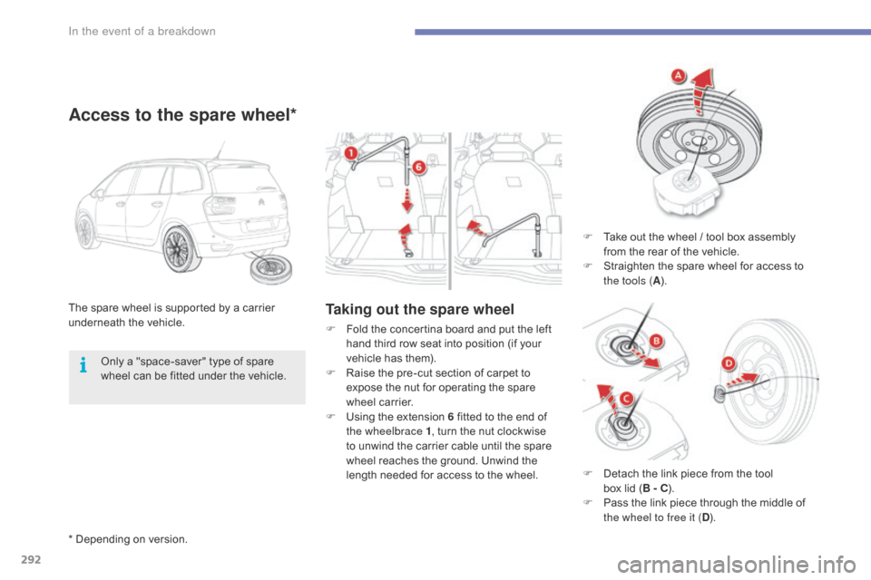
Taking out the spare wheelThe spare wheel is supported by a carrier underneath t he v ehicle.
Access to the spare wheel*
F Take out the wheel / tool box assembly f
rom the rear of the vehicle.
F
S
traighten the spare wheel for access to
t
he tools ( A).
F
F
old
the
concertina
board
and
put
the
left
h
and
third
row
seat
into
position
(if
your
v
ehicle
has
them).
F
R
aise
the
pre-cut
section
of
carpet
to
e
xpose
the
nut
for
operating
the
spare
w
heel
carrier.
F
U
sing
the
extension
6
fitted
to
the
end
of
t
he wheelbrace 1 ,
turn
the
nut
clockwise
t
o
unwind
the
carrier
cable
until
the
spare
w
heel
reaches
the
ground.
Unwind
the
l
ength
needed
for
access
to
the
wheel.
Only
a
"space-saver"
type
of
spare
w
heel
can
be
fitted
under
the
vehicle.
*
Depending
on
version. F
D
etach the link piece from the tool
b
ox lid ( B - C).
F
P
ass the link piece through the middle of
t
he wheel to free it ( D).
In the event of a breakdown