ESP Citroen JUMPY 2016 2.G Owners Manual
[x] Cancel search | Manufacturer: CITROEN, Model Year: 2016, Model line: JUMPY, Model: Citroen JUMPY 2016 2.GPages: 595, PDF Size: 12.47 MB
Page 281 of 595
279
Jumpy _en_Chap07_info-pratiques_ed01-2016
Oil grade
Before topping-up the oil or changing the oil,
check that the oil is the correct grade for your
engine and conforms to the manufacturer's
recommendations.
Topping-up the engine oil level
The location of the oil filler cap is shown in the
corresponding underbonnet layout view.
F
U
nscrew the oil filler cap to reveal the filler
aperture.
F
A
dd oil in small quantities, avoiding any
spills on engine components (risk of fire).
F
W
ait a few minutes before checking the
level again using the dipstick.
F
A
dd more oil if necessary.
F
A
fter checking the level, carefully refit the
oil filler cap and the dipstick in its tube.
After topping-up the oil, the check when
switching on the ignition with the oil
level indicator in the instrument panel
is not valid during the 30 minutes after
topping-up.
Engine oil change
Refer to the manufacturer's service schedule
for details of the interval for this operation.
In order to maintain the reliability of the engine
and emission control system, never use
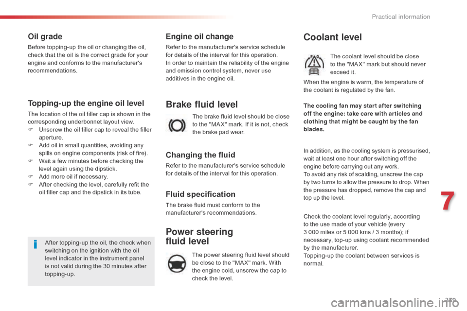
additives in the engine oil. The brake fluid level should be close
to the "MA X" mark. If it is not, check
the brake pad wear.
Brake fluid level
Changing the fluid
Refer to the manufacturer's service schedule
for details of the interval for this operation.
Fluid specification
The brake fluid must conform to the
manufacturer's recommendations.
Coolant level
The coolant level should be close
to the "MA X" mark but should never
exceed it.
In addition, as the cooling system is pressurised,
wait at least one hour after switching off the
engine before carrying out any work.
To avoid any risk of scalding, unscrew the cap
by two turns to allow the pressure to drop. When
the pressure has dropped, remove the cap and
top up the level. The cooling fan may star t after switching
off the engine: take care with ar ticles and
clothing that might be caught by the fan
blades. When the engine is warm, the temperature of
the coolant is regulated by the fan.
Check the coolant level regularly, according
to the use made of your vehicle (every
3 000
miles or 5 000 kms / 3 months); if
necessary, top-up using coolant recommended
by the manufacturer.
Topping-up the coolant between services is
normal.
Power steering
fluid level
The power steering fluid level should
be close to the "MA X" mark. With
the engine cold, unscrew the cap to
check the level.
7
Practical information
Page 283 of 595
281
Jumpy _en_Chap07_info-pratiques_ed01-2016
Checks
12 V battery
The battery does not require any maintenance.
However, check regularly that the terminals
are correctly tightened (versions without quick
release terminals) and that the connections
are clean.Refer to the manufacturer's
service schedule for details of the
replacement intervals for these
components.
Air filter and passenger compartment filter
Replace the oil filter each time the
engine oil is changed.
Refer to the manufacturer's
service schedule for details of
the replacement interval for this
component.
Oil filterParticle filter (Diesel)
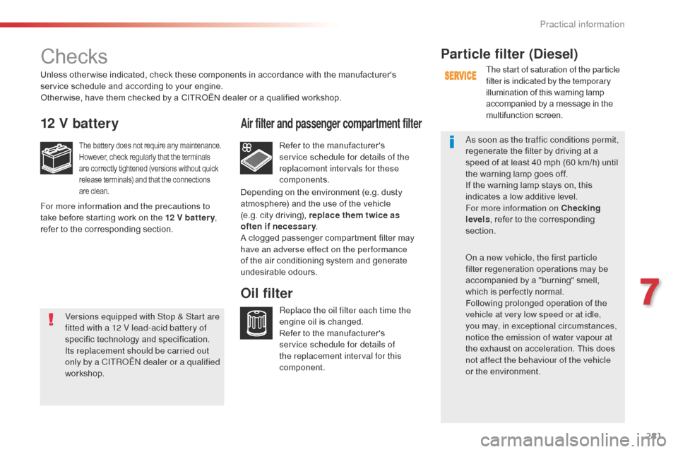
The start of saturation of the particle
filter is indicated by the temporary
illumination of this warning lamp
accompanied by a message in the
multifunction screen.
As soon as the traffic conditions permit,
regenerate the filter by driving at a
speed of at least 40 mph (60 km/h) until
the warning lamp goes off.
If the warning lamp stays on, this
indicates a low additive level.
For more information on Checking
levels , refer to the corresponding
section.
On a new vehicle, the first particle
filter regeneration operations may be
accompanied by a "burning" smell,
which is per fectly normal.
Following prolonged operation of the
vehicle at very low speed or at idle,
you may, in exceptional circumstances,
notice the emission of water vapour at
the exhaust on acceleration. This does
not affect the behaviour of the vehicle
or the environment.
Unless other wise indicated, check these components in accordance with the manufacturer's
service schedule and according to your engine.
Other wise, have them checked by a CITROËN dealer or a qualified workshop.
For more information and the precautions to
take before starting work on the 12 V batter y
,
refer to the corresponding section. Depending on the environment (e.g. dusty
atmosphere) and the use of the vehicle
(e.g. city driving), replace them twice as
often if necessar y
.
A clogged passenger compartment filter may
have an adverse effect on the per formance
of the air conditioning system and generate
undesirable odours.
Versions equipped with Stop & Start are
fitted with a 12 V lead-acid battery of
specific technology and specification.
Its replacement should be carried out
only by a CITROËN dealer or a qualified
workshop.
7
Practical information
Page 285 of 595
283
Jumpy _en_Chap07_info-pratiques_ed01-2016
AdBlue® and SCR system
for BlueHDi Diesel engines
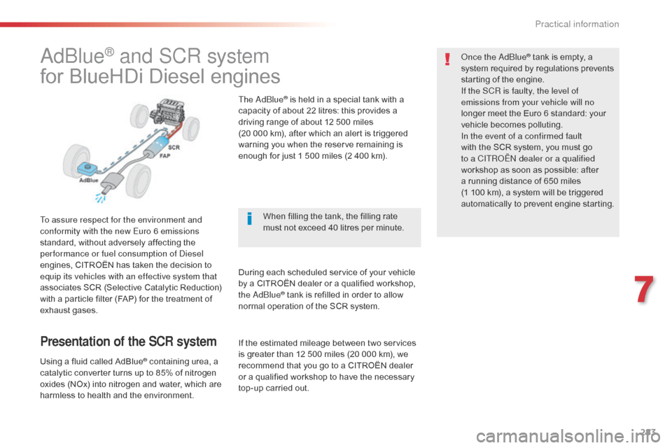
To assure respect for the environment and
conformity with the new Euro 6 emissions
standard, without adversely affecting the
per formance or fuel consumption of Diesel
engines, CITROËN has taken the decision to
equip its vehicles with an effective system that
associates SCR (Selective Catalytic Reduction)
with a particle filter (FAP) for the treatment of
exhaust gases.
Presentation of the SCR system
Using a fluid called AdBlue® containing urea, a
catalytic converter turns up to 85% of nitrogen
oxides (NOx) into nitrogen and water, which are
harmless to health and the environment. The AdBlue
® is held in a special tank with a
capacity of about 22 litres: this provides a
driving range of about 12 500 miles
(20 000 km), after which an alert is triggered
warning you when the reserve remaining is
enough for just 1 500 miles (2 400 km).
During each scheduled service of your vehicle
by a CITROËN dealer or a qualified workshop,
the AdBlue
® tank is refilled in order to allow
normal operation of the SCR system. Once the AdBlue
® tank is empty, a
s
ystem required by regulations prevents
starting of the engine.
If the SCR
is faulty, the level of
emissions from your vehicle will no
longer meet the Euro 6 standard: your
vehicle becomes polluting.
In the event of a confirmed fault
with the SCR system, you must go
to a CITROËN dealer or a qualified
workshop as soon as possible: after
a running distance of 650 miles
(1
100 km), a system will be triggered
automatically to prevent engine starting.
When filling the tank, the filling rate
must not exceed 40 litres per minute.
If the estimated mileage between two services
is greater than 12 500 miles (20 000 km), we
recommend that you go to a CITROËN dealer
or a qualified workshop to have the necessary
top-up carried out.
7
Practical information
Page 292 of 595

290
Jumpy _en_Chap08_En-cas-de-panne_ed01-2016
This kit is stowed in the tool box. This kit consists of a compressor and a sealant
cartridge.
It allows the temporary repair of a tyre.
You are then able to go to the nearest garage.
It is designed to repair most punctures which
could affect the tyre, located on the tyre tread
or shoulder.
Its compressor can be used to check and
adjust the pressure of the tyre.
Temporary puncture repair kit
Access to the kit
1. 12 V compressor. T o temporarily repair a tyre using an
integral sealant cartridge and adjust the
tyre pressure.
2.
T
owing eye. The tyre inflation pressures are given on this
label.
The vehicle's electric system allows the
connection of the compressor for long
enough to inflate a tyre after a puncture
repair.
Use only the two 12 V sockets
located at the front to connect your
compressor.
For more information on To w i n g
, refer
to the corresponding section.
List of tools
These tools are specific to your vehicle and can
vary according to equipment. Do not use them
for other purposes.
For more information on the Tool box ,
refer to the corresponding section.
In the event of a breakdown
Page 297 of 595
295
Jumpy _en_Chap08_En-cas-de-panne_ed01-2016
Checking / adjusting tyre
pressures
You can also use the compressor without
injecting any product, to check and if necessary
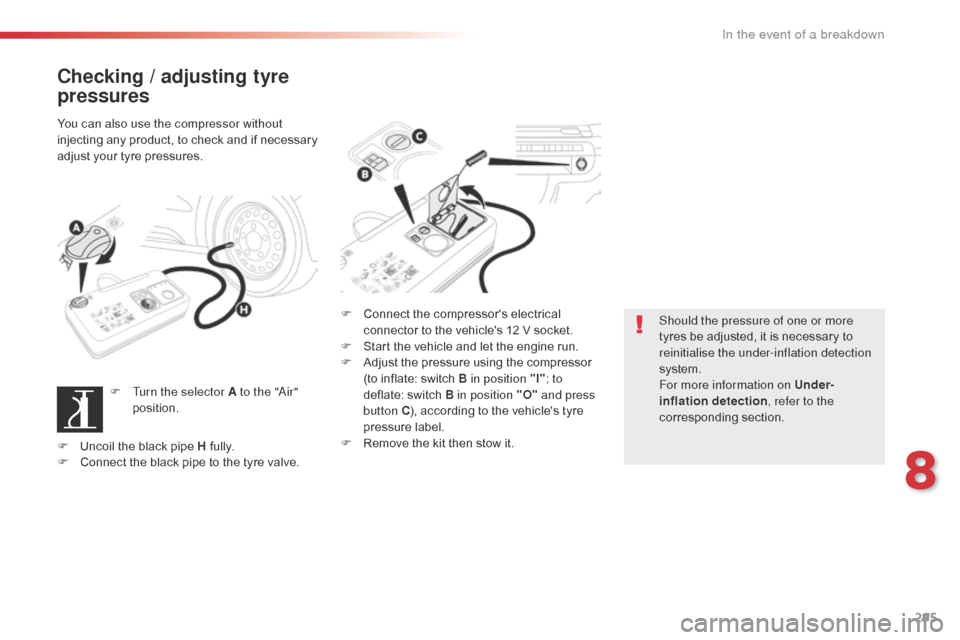
adjust your tyre pressures.F
T
urn the selector A to the "Air"
position. F
C
onnect the compressor's electrical
connector to the vehicle's 12 V socket.
F
S
tart the vehicle and let the engine run.
F
A
djust the pressure using the compressor
(to inflate: switch B in position "I" ; to
deflate: switch B in position "O" and press
button C ), according to the vehicle's tyre
pressure label.
F
R
emove the kit then stow it.Should the pressure of one or more
tyres be adjusted, it is necessary to
reinitialise the under-inflation detection
system.
For more information on Under-
inflation detection
, refer to the
corresponding section.
F
U
ncoil the black pipe H fully.
F
C
onnect the black pipe to the tyre valve.
8
In the event of a breakdown
Page 298 of 595
296
Jumpy _en_Chap08_En-cas-de-panne_ed01-2016
Changing a wheel
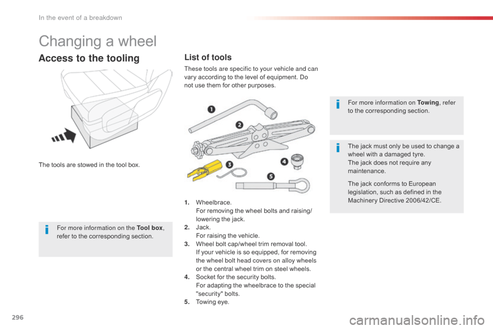
The tools are stowed in the tool box.
Access to the tooling
1. Wheelbrace. For removing the wheel bolts and raising/
lowering the jack.
2.
J
ack.
F
or raising the vehicle.
3.
W
heel bolt cap/wheel trim removal tool.
I
f your vehicle is so equipped, for removing
the wheel bolt head covers on alloy wheels
or the central wheel trim on steel wheels.
4.
S
ocket for the security bolts.
F
or adapting the wheelbrace to the special
"security" bolts.
5.
T
owing eye. For more information on To w i n g
, refer
to the corresponding section.
The jack must only be used to change a
wheel with a damaged tyre.
The jack does not require any
maintenance.
The jack conforms to European
legislation, such as defined in the
Machinery Directive 2006/42/CE.
List of tools
These tools are specific to your vehicle and can
vary according to the level of equipment. Do
not use them for other purposes.
For more information on the Tool box ,
refer to the corresponding section.
In the event of a breakdown
Page 299 of 595
297
Jumpy _en_Chap08_En-cas-de-panne_ed01-2016
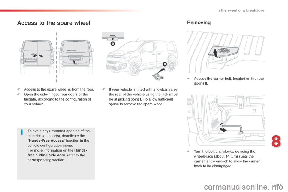
F Access to the spare wheel is from the rear.
F O pen the side-hinged rear doors or the
tailgate, according to the configuration of
your vehicle. F
A
ccess the carrier bolt, located on the rear
door sill.
F
T
urn the bolt anti-clockwise using the
wheelbrace (about 14 turns) until the
carrier is low enough to allow the carrier
hook to be disengaged.
Access to the spare wheel
F If your vehicle is fitted with a towbar, raise the rear of the vehicle using the jack (must
be at jacking point B ) to allow sufficient
space to remove the spare wheel.
Removing
To avoid any unwanted opening of the
electric side door(s), deactivate the
" Hands-Free Access " function in the
vehicle configuration menu.
For more information on the Hands-
free sliding side door , refer to the
corresponding section.
8
In the event of a breakdown
Page 304 of 595
302
Jumpy _en_Chap08_En-cas-de-panne_ed01-2016
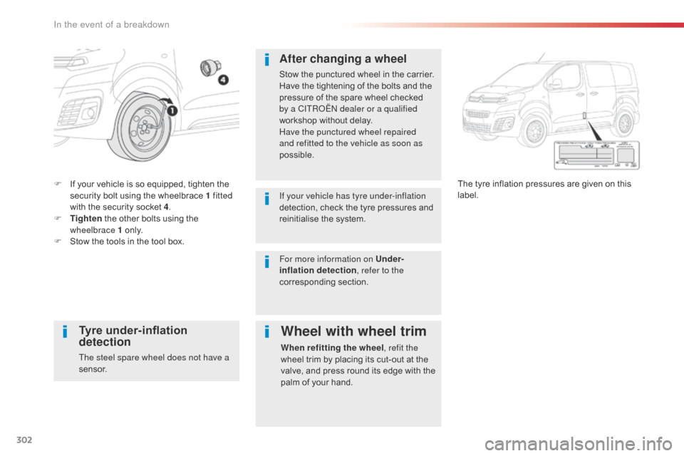
F If your vehicle is so equipped, tighten the security bolt using the wheelbrace 1 fitted
with the security socket 4 .
F
T
ighten the other bolts using the
wheelbrace 1 o n l y.
F
S
tow the tools in the tool box. The tyre inflation pressures are given on this
label.
After changing a wheel
Stow the punctured wheel in the carrier.
Have the tightening of the bolts and the
pressure of the spare wheel checked
by a CITROËN dealer or a qualified
workshop without delay.
Have the punctured wheel repaired
and refitted to the vehicle as soon as
possible.
If your vehicle has tyre under-inflation
detection, check the tyre pressures and
reinitialise the system.
Tyre under-inflation
detection
The steel spare wheel does not have a
sensor.
Wheel with wheel trim
When refitting the wheel
, refit the
wheel trim by placing its cut-out at the
valve, and press round its edge with the
palm of your hand.
For more information on Under-
inflation detection
, refer to the
corresponding section.
In the event of a breakdown
Page 306 of 595

304
Jumpy _en_Chap08_En-cas-de-panne_ed01-2016
Front lamps
Xenon headlamps
For more information on Changing a bulb
and in particular the types of bulb, refer to the
corresponding section.
Halogen headlamps
For more information on Changing a bulb
and in particular the types of bulb, refer to the
corresponding section.
For H7 type bulbs with lugs... take care
to observe their correct installation
so as to ensure the best lighting
performance.
Front fog lamps
Ty p e D , H11-55W
In some weather conditions (e.g. low
temperature or humidity), the presence
of misting on the internal sur face of the
glass of the headlamps and rear lamps
is normal; it disappears after the lamps
have been on for a few minutes.
1.
M
ain beam headlamps.
Ty
p e C , H1-55W.
2.
D
ipped beam headlamps.
Ty
p e E , D8S 25W
3.
D
irection indicators.
Ty
p e B , PY21W-21W (amber)
1.
S
idelamps.
Ty
p e A , W5W-5W.
2.
M
ain beam headlamps.
Ty
p e C , H1-55W
3.
D
ipped beam headlamps.
Ty
p e C , H7-55W
4.
D
aytime running lamps.
Ty
p e A , W21W LL-21W
5.
D
irection indicators.
Ty
p e B , PY21W-21W (amber)
In the event of a breakdown
Page 312 of 595
310
Jumpy _en_Chap08_En-cas-de-panne_ed01-2016
Rear lamps
(side-hinged rear doors)
For more information on Changing a bulb and
in particular, the types of bulbs, refer to the
corresponding section.
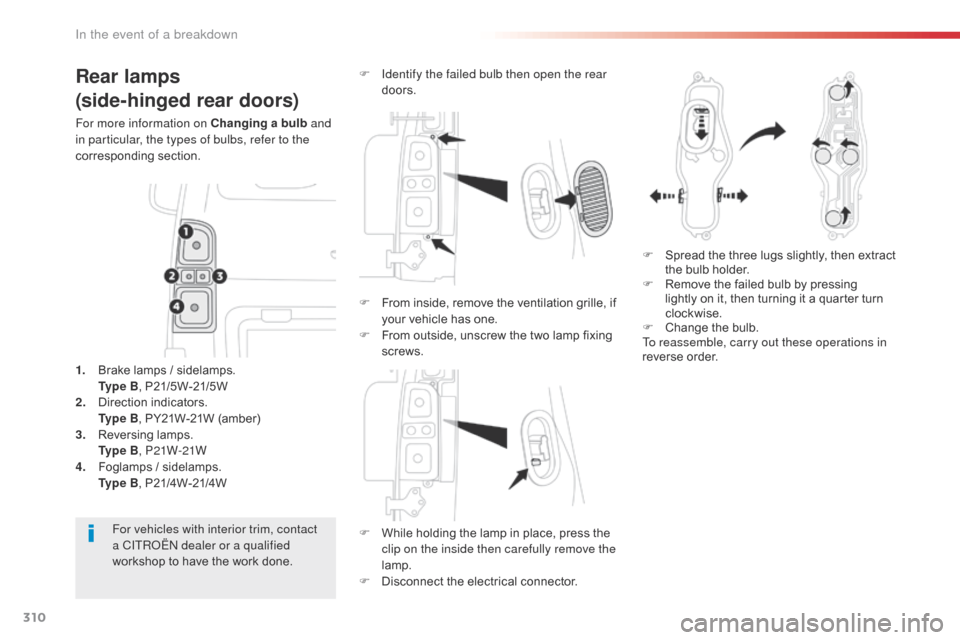
F
W
hile holding the lamp in place, press the
clip on the inside then carefully remove the
lamp.
F
D
isconnect the electrical connector.
For vehicles with interior trim, contact
a CITROËN dealer or a qualified
workshop to have the work done.
1.
B
rake lamps / sidelamps.
Ty
p e B, P21/5W-21/5W
2.
D
irection indicators.
Ty
p e B, PY21W-21W (amber)
3.
R
eversing lamps.
Ty
p e B, P21W-21W
4.
F
oglamps / sidelamps.
Ty
p e B, P21/4W-21/4W F
I
dentify the failed bulb then open the rear
doors.
F
S
pread the three lugs slightly, then extract
the bulb holder.
F
R
emove the failed bulb by pressing
lightly on it, then turning it a quarter turn
clockwise.
F
C
hange the bulb.
To reassemble, carry out these operations in
reverse order.
F
F
rom inside, remove the ventilation grille, if
your vehicle has one.
F
F
rom outside, unscrew the two lamp fixing
screws.
In the event of a breakdown