Citroen JUMPY 2016 2.G Owner's Manual
Manufacturer: CITROEN, Model Year: 2016, Model line: JUMPY, Model: Citroen JUMPY 2016 2.GPages: 595, PDF Size: 12.47 MB
Page 101 of 595
99
Jumpy _en_Chap03_ergonomie-et-confort_ed01-2016
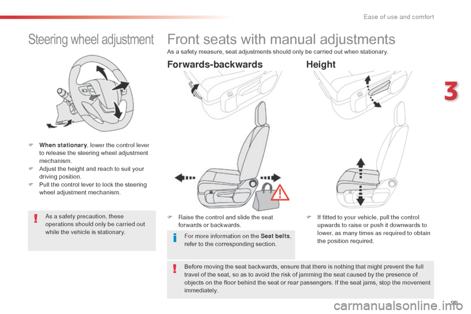
Steering wheel adjustment
F When stationary, lower the control lever
to release the steering wheel adjustment
mechanism.
F
A
djust the height and reach to suit your
driving position.
F
P
ull the control lever to lock the steering
wheel adjustment mechanism.
As a safety precaution, these
operations should only be carried out
while the vehicle is stationary.
Front seats with manual adjustments
F Raise the control and slide the seat for wards or backwards. F
I f fitted to your vehicle, pull the control
upwards to raise or push it downwards to
lower, as many times as required to obtain
the position required.
Forwards-backwards Height
As a safety measure, seat adjustments should only be carried out when stationary.
Before moving the seat backwards, ensure that there is nothing that might prevent the full
travel of the seat, so as to avoid the risk of jamming the seat caused by the presence of
objects on the floor behind the seat or rear passengers. If the seat jams, stop the movement
immediately. For more information on the Seat belts ,
refer to the corresponding section.
3
Ease of use and comfort
Page 102 of 595

100
Jumpy _en_Chap03_ergonomie-et-confort_ed01-2016
F Turn the knob to adjust the backrest.
Backrest angle
F Turn the knob manually to obtain the desired level of lumbar support.
Lumbar
F Pull the control fully up and move the backrest for ward or backward.
Ease of use and comfort
Page 103 of 595

101
Jumpy _en_Chap03_ergonomie-et-confort_ed01-2016
F Place the head restraint in the low position, and if fitted to your vehicle, raise the
armrest and fold the table on the back of
the seat.
Table position for the
driver's and/or the
front passenger's seat
backrest
Check that there is no object that could
inter fere with the movement of a seat,
both above and below.
On the front passenger's side, this position
allows long objects to be carried.
On the driver's side, this position allows rear
passengers to be helped out of the vehicle (by
the emergency services).
F
P
ull the control fully up and tip the backrest
forward.
To return to the normal position, pull the
control up to release the backrest, then pull the
backrest up to its raised position.
3
Ease of use and comfort
Page 104 of 595
102
Jumpy _en_Chap03_ergonomie-et-confort_ed01-2016
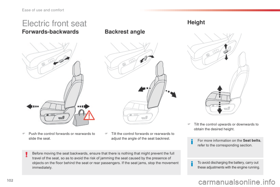
Electric front seat
Forwards-backwardsBackrest angleHeight
To avoid discharging the battery, carry out
these adjustments with the engine running.
For more information on the Seat belts
,
refer to the corresponding section.
F
P
ush the control for wards or rear wards to
slide the seat. F
T
ilt the control for wards or rear wards to
adjust the angle of the seat backrest. F
T
ilt the control upwards or downwards to
obtain the desired height.
Before moving the seat backwards, ensure that there is nothing that might prevent the full
travel of the seat, so as to avoid the risk of jamming the seat caused by the presence of
objects on the floor behind the seat or rear passengers. If the seat jams, stop the movement
immediately.
Ease of use and comfort
Page 105 of 595
103
Jumpy _en_Chap03_ergonomie-et-confort_ed01-2016
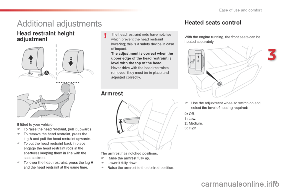
With the engine running, the front seats can be
heated separately.
Heated seats control
If fitted to your vehicle.
F T o raise the head restraint, pull it upwards.
F
T
o remove the head restraint, press the
lug
A and pull the head restraint upwards.
F
T
o put the head restraint back in place,
engage the head restraint rods in the
apertures keeping them in line with the
seat backrest.
F
T
o lower the head restraint, press the lug A
and the head restraint at the same time. The head restraint rods have notches
which prevent the head restraint
lowering; this is a safety device in case
of impact.
The adjustment is correct when the
upper edge of the head restraint is
level with the top of the head.
Never drive with the head restraints
removed; they must be in place and
adjusted correctly.
Head restraint height
adjustment
Additional adjustments
Armrest
The armrest has notched positions.
F
R aise the armrest fully up.
F
L
ower it fully down.
F
R
aise the armrest to the desired position. F
U
se the adjustment wheel to switch on and
select the level of heating required:
0: Of f.
1: Low.
2: Medium.
3: High.
3
Ease of use and comfort
Page 106 of 595
104
Jumpy _en_Chap03_ergonomie-et-confort_ed01-2016
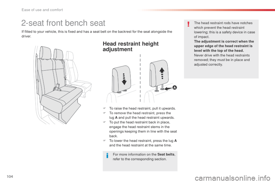
Head restraint height
adjustment
F To raise the head restraint, pull it upwards.
F T o remove the head restraint, press the
lug
A and pull the head restraint upwards.
F
T
o put the head restraint back in place,
engage the head restraint stems in the
openings keeping them in line with the seat
back.
F
T
o lower the head restraint, press the lug A
and the head restraint at the same time. The head restraint rods have notches
which prevent the head restraint
lowering; this is a safety device in case
of impact.
The adjustment is correct when the
upper edge of the head restraint is
level with the top of the head.
Never drive with the head restraints
removed; they must be in place and
adjusted correctly.
2-seat front bench seat
If fitted to your vehicle, this is fixed and has a seat belt on the backrest for the seat alongside the
driver.
For more information on the Seat belts,
refer to the corresponding section.
Ease of use and comfort
Page 107 of 595
105
Jumpy _en_Chap03_ergonomie-et-confort_ed01-2016
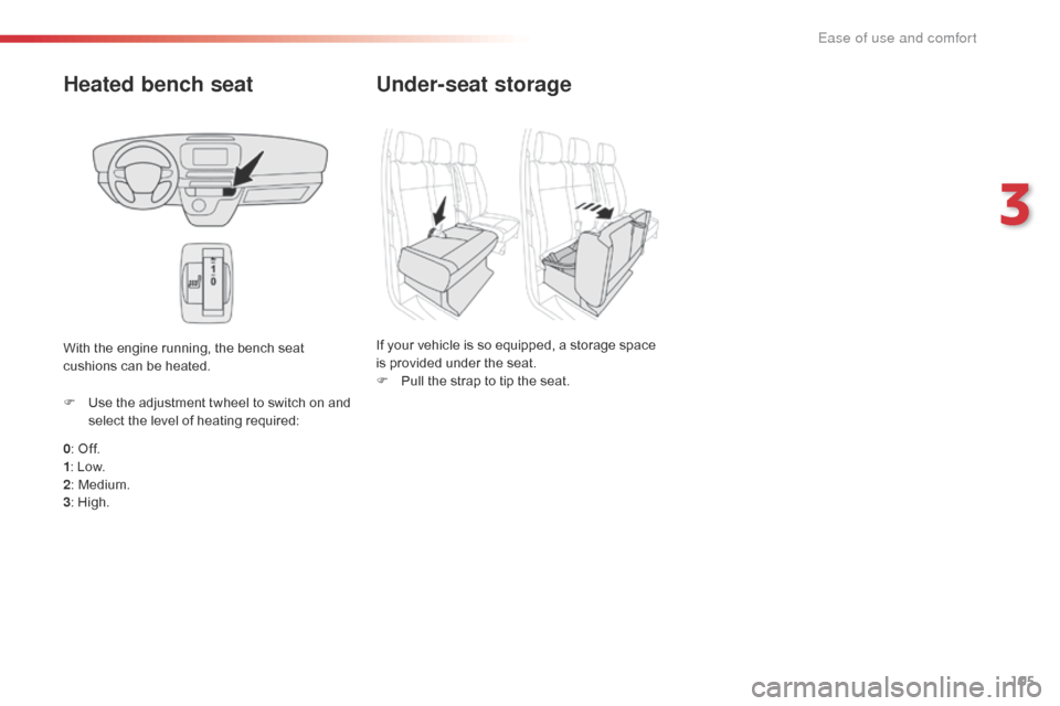
Heated bench seat
0: Off.
1 : Low.
2 : Medium.
3 : High.
F
U
se the adjustment twheel to switch on and
select the level of heating required:
With the engine running, the bench seat
cushions can be heated.
Under-seat storage
If your vehicle is so equipped, a storage space
is provided under the seat.
F
P
ull the strap to tip the seat.
3
Ease of use and comfort
Page 108 of 595

106
Jumpy _en_Chap03_ergonomie-et-confort_ed01-2016
Moduwork
Removing the flap
Removable flap
F Holding the flap with one hand, with your other hand turn the control at the top of the
flap to release it.
F
L
ower the flap to remove it from its
housing.
The cushion of the outer seat of the bench
seat can be raised up to the backrest to create
additional loading space in the cab.
A flap in the partition can be removed to allow
long objects to be carried.
Once the removable flap has been
removed, you can load long objects
under the outer seat. F
S
tow it behind the driver's seat, clipping it
to the fixing lugs.
F
T
urn the control at the top of the flap to
secure it.
Ease of use and comfort
Page 109 of 595

107
Jumpy _en_Chap03_ergonomie-et-confort_ed01-2016
When the outer seat is raised and
the flap removed, you must fit the
non-slip net.
Refer to the Non-slip net section.
Never
place your hand under the
seat cushion to guide the seat
upward; risk of trapping your fingers.
Only the strap should be used.
Refitting the flap
F Offer up the flap at an angle, with the yellow hinges pointing downward.
F
P
lace the hinges in their housings then
push fully down (to avoid vibrations).
F
W
ith one hand, raise the flap to close it,
then with the other hand turn the control at
the top of the flap to secure it.
Folding the seat cushion
Raising the seat cushion
F With one hand, pull the strap firmly for ward to release the seat cushion. F
A s
trut raises the cushion onto the
backrest.
3
Ease of use and comfort
Page 110 of 595
108
Jumpy _en_Chap03_ergonomie-et-confort_ed01-2016
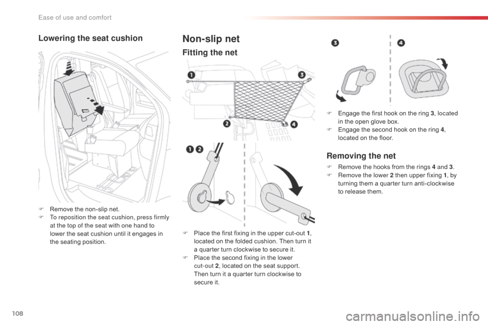
Lowering the seat cushion
F Remove the non-slip net.
F T o reposition the seat cushion, press firmly
at the top of the seat with one hand to
lower the seat cushion until it engages in
the seating position.
Non-slip net
Fitting the net
F Place the first fixing in the upper cut-out 1 ,
located on the folded cushion. Then turn it
a quarter turn clockwise to secure it.
F
P
lace the second fixing in the lower
cut-out
2, located on the seat support.
Then turn it a quarter turn clockwise to
secure it. F
E
ngage the first hook on the ring 3
, located
in the open glove box.
F
E
ngage the second hook on the ring 4
,
located on the floor.
Removing the net
F Remove the hooks from the rings 4 and 3 .
F R emove the lower 2 then upper fixing 1 , by
turning them a quarter turn anti-clockwise
to release them.
Ease of use and comfort