ECU Citroen JUMPY 2016 2.G Workshop Manual
[x] Cancel search | Manufacturer: CITROEN, Model Year: 2016, Model line: JUMPY, Model: Citroen JUMPY 2016 2.GPages: 595, PDF Size: 12.47 MB
Page 275 of 595
273
Jumpy _en_Chap07_info-pratiques_ed01-2016
Roof bars / Roof rack
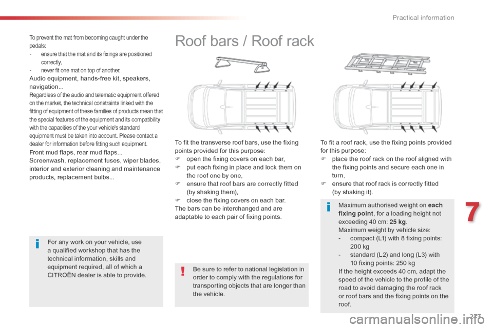
To fit the transverse roof bars, use the fixing
points provided for this purpose:
F
o
pen the fixing covers on each bar,
F
p
ut each fixing in place and lock them on
the roof one by one,
F
e
nsure that roof bars are correctly fitted
(by shaking them),
F
c
lose the fixing covers on each bar.
The bars can be interchanged and are
adaptable to each pair of fixing points. To fit a roof rack, use the fixing points provided
for this purpose:
F
p
lace the roof rack on the roof aligned with
the fixing points and secure each one in
turn,
F
e
nsure that roof rack is correctly fitted
(by shaking it).
Be sure to refer to national legislation in
order to comply with the regulations for
transporting objects that are longer than
the vehicle. Maximum authorised weight on each
fixing point
, for a loading height not
exceeding 40 cm: 25 kg.
Maximum weight by vehicle size:
-
c
ompact (L1) with 8 fixing points:
200 kg
-
s
tandard (L2) and long (L3) with
10 fixing points: 250 kg
If the height exceeds 40 cm, adapt the
speed of the vehicle to the profile of the
road to avoid damaging the roof rack
or roof bars and the fixing points on the
roof.
Front mud flaps, rear mud flaps...
Screenwash, replacement fuses, wiper blades,
interior and exterior cleaning and maintenance
products, replacement bulbs...
To prevent the mat from becoming caught under the
pedals:
- ensure that the mat and its fixings are positioned
c o r r e c t l y,
- never fit one mat on top of another.Audio equipment, hands-free kit, speakers,
navigation...
Regardless of the audio and telematic equipment offered
on the market, the technical constraints linked with the
fitting of equipment of these families of products mean that
the special features of the equipment and its compatibility
with the capacities of the your vehicle's standard
equipment must be taken into account. Please contact a
dealer for information before fitting such equipment.
For any work on your vehicle, use
a qualified workshop that has the
technical information, skills and
equipment required, all of which a
CITROËN dealer is able to provide.
7
Practical information
Page 289 of 595

287
Jumpy _en_Chap08_En-cas-de-panne_ed01-2016
Warning triangle (stowing)
Before leaving your vehicle to set up
and install the triangle, switch on the
hazard warning lamps and put on your
high visibility vest.
This safety equipment should be used in
addition to the hazard warning lamps.
Its presence in the vehicle is mandatory.
Placing the triangle in the
road
Refer to the manufacturer's instructions on
unfolding and assembly supplied with the
triangle. F
P
lace the triangle behind the vehicle, as
required by the legislation in force in your
c o unt r y.
The triangle is available as an
accessory; contact a CITROËN dealer
or a qualified workshop.
Tool box
Access
The tool box is located under the left-hand front
seat.
As a safety measure, the bars 1 and
2
prevent the box escaping from its
housing, if it is not correctly secured.
8
In the event of a breakdown
Page 290 of 595

288
Jumpy _en_Chap08_En-cas-de-panne_ed01-2016
Stowing
F Press the latches A and slide them inwards to release the box.
F
L
ift the box slightly then pull it as far as it
will go to take it past bar 1 .
F
T
hen, lift the box upwards to take it past
bar 2 . F
U nclip the fixings B on the cover, then
open it for access to the tools.
OpeningRemoving
Pull on the box to check that it is secure
in its housing.
F
O
ffer up the box with the front inclined
upwards.
F
T
o take it past bar 2 , push the box in and
down. F
T
o take it past bar 1
, raise the box slightly
then push it fully in.
F
R
efit the cover on the box and clip the
fixings B. F
O
nce the box is fully home
in its housing,
push it against the floor carpet then slide
the latches A outwards to secure it.
In the event of a breakdown
Page 291 of 595
289
Jumpy _en_Chap08_En-cas-de-panne_ed01-2016
If your vehicle is equipped
with a temporary puncture
repair kit
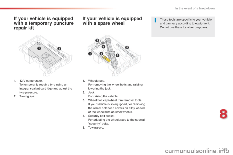
1. 12 V compressor. To temporarily repair a tyre using an
integral sealant cartridge and adjust the
tyre pressure.
2.
T
owing eye.
If your vehicle is equipped
with a spare wheel
1. Wheelbrace. F or removing the wheel bolts and raising/
lowering the jack.
2.
J
ack.
F
or raising the vehicle.
3.
W
heel bolt cap/wheel trim removal tools.
I
f your vehicle is so equipped, for removing
the wheel bolt head covers on alloy wheels
or the wheel trim on steel wheels.
4.
S
ecurity bolt socket.
F
or adapting the wheelbrace to the special
"security" bolts.
5.
T
owing eye. These tools are specific to your vehicle
and can vary according to equipment.
Do not use them for other purposes.
8
In the event of a breakdown
Page 298 of 595
296
Jumpy _en_Chap08_En-cas-de-panne_ed01-2016
Changing a wheel
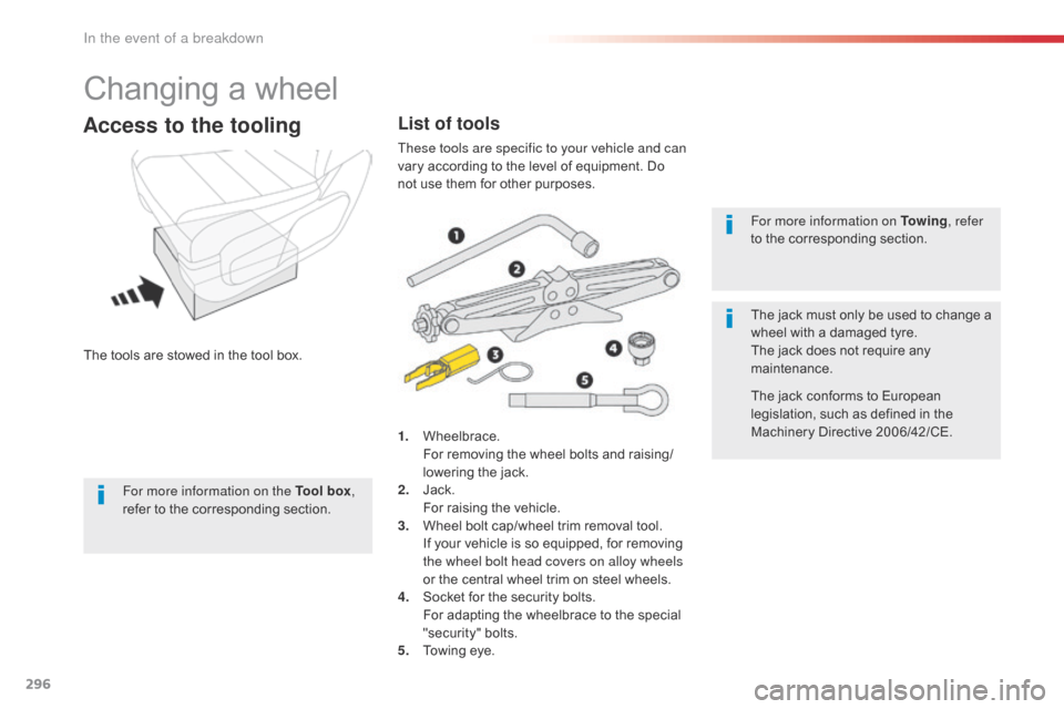
The tools are stowed in the tool box.
Access to the tooling
1. Wheelbrace. For removing the wheel bolts and raising/
lowering the jack.
2.
J
ack.
F
or raising the vehicle.
3.
W
heel bolt cap/wheel trim removal tool.
I
f your vehicle is so equipped, for removing
the wheel bolt head covers on alloy wheels
or the central wheel trim on steel wheels.
4.
S
ocket for the security bolts.
F
or adapting the wheelbrace to the special
"security" bolts.
5.
T
owing eye. For more information on To w i n g
, refer
to the corresponding section.
The jack must only be used to change a
wheel with a damaged tyre.
The jack does not require any
maintenance.
The jack conforms to European
legislation, such as defined in the
Machinery Directive 2006/42/CE.
List of tools
These tools are specific to your vehicle and can
vary according to the level of equipment. Do
not use them for other purposes.
For more information on the Tool box ,
refer to the corresponding section.
In the event of a breakdown
Page 301 of 595
299
Jumpy _en_Chap08_En-cas-de-panne_ed01-2016
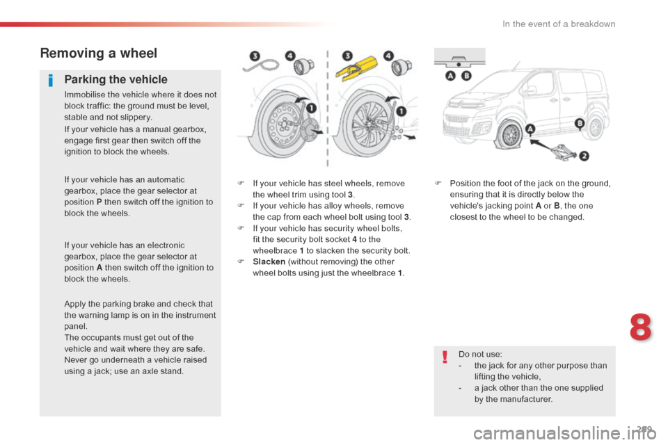
F If your vehicle has steel wheels, remove the wheel trim using tool 3 .
F
I
f your vehicle has alloy wheels, remove
the cap from each wheel bolt using tool 3 .
F
I
f your vehicle has security wheel bolts,
fit the security bolt socket 4 to the
wheelbrace
1 to slacken the security bolt.
F
S
lacken (without removing) the other
wheel bolts using just the wheelbrace 1 .F
P osition the foot of the jack on the ground,
ensuring that it is directly below the
vehicle's jacking point A or B , the one
closest to the wheel to be changed.
Removing a wheel
Parking the vehicle
Immobilise the vehicle where it does not
block traffic: the ground must be level,
stable and not slippery.
Do not use:
-
t
he jack for any other purpose than
lifting the vehicle,
-
a j
ack other than the one supplied
by the manufacturer.
If your vehicle has a manual gearbox,
engage first gear then switch off the
ignition to block the wheels.
If your vehicle has an automatic
gearbox, place the gear selector at
position P then switch off the ignition to
block the wheels.
If your vehicle has an electronic
gearbox, place the gear selector at
position A then switch off the ignition to
block the wheels.
Apply the parking brake and check that
the warning lamp is on in the instrument
panel.
The occupants must get out of the
vehicle and wait where they are safe.
Never go underneath a vehicle raised
using a jack; use an axle stand.
8
In the event of a breakdown
Page 303 of 595
301
Jumpy _en_Chap08_En-cas-de-panne_ed01-2016
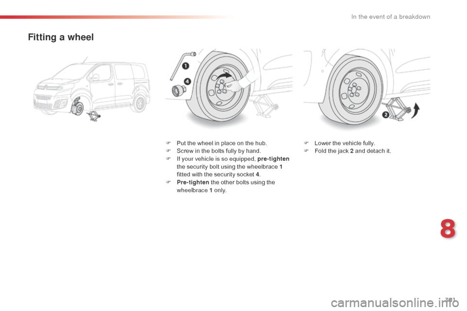
Fitting a wheel
F Put the wheel in place on the hub.
F S crew in the bolts fully by hand.
F
I
f your vehicle is so equipped, pre- tighten
the security bolt using the wheelbrace 1
fitted with the security socket 4 .
F
P
re-tighten the other bolts using the
wheelbrace 1 o n l y. F
L ower the vehicle fully.
F F old the jack 2 and detach it.
8
In the event of a breakdown
Page 304 of 595
302
Jumpy _en_Chap08_En-cas-de-panne_ed01-2016
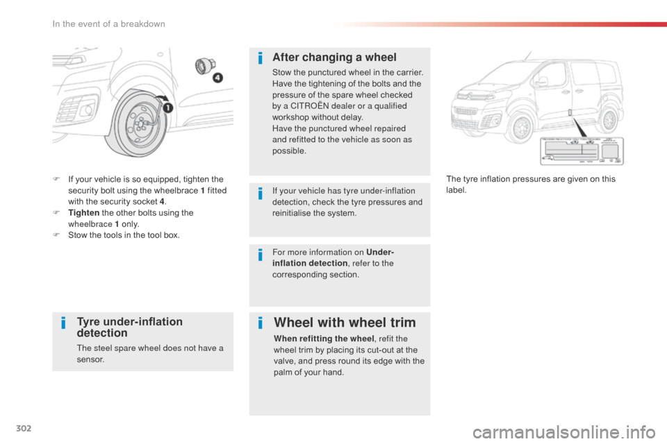
F If your vehicle is so equipped, tighten the security bolt using the wheelbrace 1 fitted
with the security socket 4 .
F
T
ighten the other bolts using the
wheelbrace 1 o n l y.
F
S
tow the tools in the tool box. The tyre inflation pressures are given on this
label.
After changing a wheel
Stow the punctured wheel in the carrier.
Have the tightening of the bolts and the
pressure of the spare wheel checked
by a CITROËN dealer or a qualified
workshop without delay.
Have the punctured wheel repaired
and refitted to the vehicle as soon as
possible.
If your vehicle has tyre under-inflation
detection, check the tyre pressures and
reinitialise the system.
Tyre under-inflation
detection
The steel spare wheel does not have a
sensor.
Wheel with wheel trim
When refitting the wheel
, refit the
wheel trim by placing its cut-out at the
valve, and press round its edge with the
palm of your hand.
For more information on Under-
inflation detection
, refer to the
corresponding section.
In the event of a breakdown
Page 314 of 595
312
Jumpy _en_Chap08_En-cas-de-panne_ed01-2016
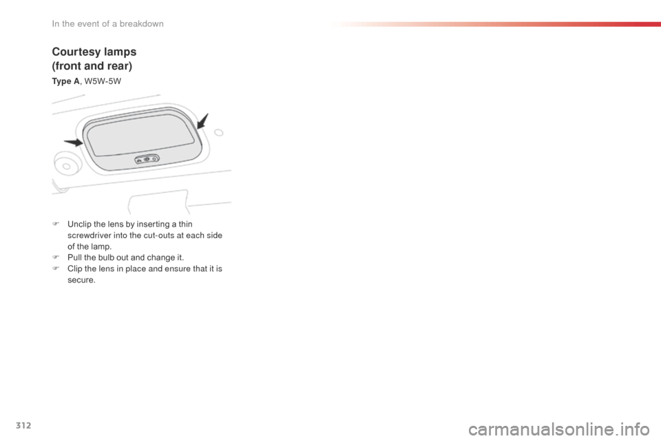
Courtesy lamps
(front and rear)
Ty p e A, W5W-5W
F
U
nclip the lens by inserting a thin
screwdriver into the cut-outs at each side
of the lamp.
F
P
ull the bulb out and change it.
F
C
lip the lens in place and ensure that it is
secure.
In the event of a breakdown
Page 317 of 595

315
Jumpy _en_Chap08_En-cas-de-panne_ed01-2016
Courtesy lamps
(front and rear)
For the replacement of this type of LED lamp
and light guide, contact a CITROËN dealer or a
qualified workshop.
A replacement kit for the LEDs is available from
CITROËN dealers.Rear lamps
For more information on Changing a bulb and
in particular, the types of bulbs, refer to the
corresponding section.
Platform cab
F Identify the failed bulb.
F R emove the four screws securing the lens.
F
P
ull the lens towards you.
F
R
emove the failed bulb by pressing lightly
on it and then turning it a quarter turn
clockwise.
F
C
hange the bulb.
1.
D
irection indicators.
Ty
p e B , P21W-21W
2.
B
rake lamps.
Ty
p e B , P21W-21W
3.
S
idelamps.
Ty
p e B , R10W-10W
4.
R
eversing lamps.
Ty
p e B , P21W-21W
5.
F
oglamps.
Ty
p e B , P21W-21W To reassemble, carry out these operations in
reverse order.
8
In the event of a breakdown