Citroen JUMPY DAG 2010 2.G Owner's Manual
Manufacturer: CITROEN, Model Year: 2010, Model line: JUMPY DAG, Model: Citroen JUMPY DAG 2010 2.GPages: 225, PDF Size: 10.81 MB
Page 111 of 225
105
Battery
QUICK HELP
7
BATTERY
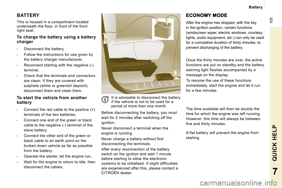
This is housed in a compartment located
underneath the floor, in front of the front
right seat. Before disconnecting the battery, you must
wait for 2 minutes after switching off the
ignition.
Never disconnect a terminal when the
engine is running.
Never charge a battery without first
disconnecting the terminals.
After every reconnection of the battery,
switch on the ignition and wait 1 minute
before starting to allow the electronic
systems to be initialised. If slight difficulties
are experienced after this, please contact a
CITROËN dealer. It is advisable to disconnect the battery
if the vehicle is not to be used for a
period of more than one month. After the engine has stopped, with the key
in the ignition position, certain functions
(windscreen wiper, electric windows, courtesy
lights, audio equipment, etc.) can only be used
for a cumulative duration of thirty minutes, to
prevent discharging of the battery.
To charge the battery using a battery
charger
- Disconnect the battery,
- Follow the instructions for use given by
the battery charger manufacturer,
- Reconnect starting with the negative (-) terminal,
- Check that the terminals and connectors are clean. If they are covered with
sulphate (white or greenish deposit),
disconnect them and clean them.
To start the vehicle from another
battery
- Connect the red cable to the positive (+) terminals of the two batteries,
- Connect one end of the green or black cable to the negative (-) terminal of the
slave battery,
- Connect the other end of the green or black cable to an earth point on the
broken down vehicle as far as possible
from the battery,
- Operate the starter, let the engine run,
- Wait for the engine to return to idle, then disconnect the cables. Once the thirty minutes are over, the active
functions are put on standby and the battery
warning light flashes accompanied by a
message on the display.
To resume the use of these functions
immediately, start the engine and let it run
for a few minutes.
The time available will then be double the
time for which the engine was left running.
However, this time will always be between
five and thirty minutes.
A flat battery will prevent the engine from
starting.
Page 112 of 225
106
Repairing a wheel
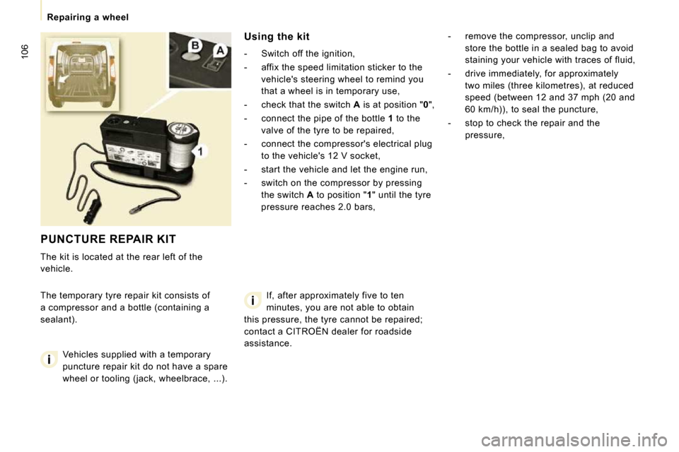
PUNCTURE REPAIR KIT
The kit is located at the rear left of the
vehicle.
The temporary tyre repair kit consists of
a compressor and a bottle (containing a
sealant). Using the kit
- Switch off the ignition,
- affix the speed limitation sticker to the
vehicle's steering wheel to remind you
that a wheel is in temporary use,
- check that the switch A is at position " 0 ",
- connect the pipe of the bottle 1 to the
valve of the tyre to be repaired,
- connect the compressor's electrical plug to the vehicle's 12 V socket,
- start the vehicle and let the engine run,
- switch on the compressor by pressing the switch A to position " 1 " until the tyre
pressure reaches 2.0 bars, - remove the compressor, unclip and
store the bottle in a sealed bag to avoid
staining your vehicle with traces of fluid,
- drive immediately, for approximately two miles (three kilometres), at reduced
speed (between 12 and 37 mph (20 and
60 km/h)), to seal the puncture,
- stop to check the repair and the pressure,
Vehicles supplied with a temporary
puncture repair kit do not have a spare
wheel or tooling (jack, wheelbrace, ...). If, after approximately five to ten
minutes, you are not able to obtain
this pressure, the tyre cannot be repaired;
contact a CITROËN dealer for roadside
assistance.
Page 113 of 225
Repairing a wheel
QUICK HELP
7
Warning, the bottle of fluid contains
ethylene-glycol, this product is harmful
if swallowed and causes irritation to the
eyes. Keep this product out of reach of
children.
The expiry date of the fluid is indicated
under the bottle.
The bottle is intended for a single use; once
opened, it must be replaced.
After use, do not discard the bottle into the
environment, take it to a CITROËN dealer or
to a specialised waste disposal site.
Do not forget to obtain a new bottle of
sealant available from CITROËN dealers.
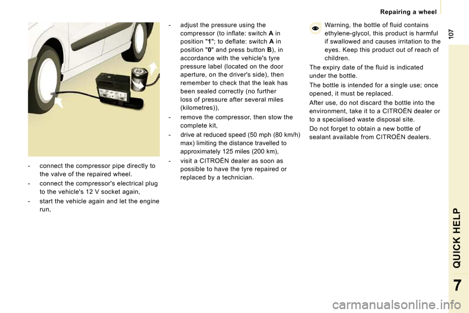
- connect the compressor pipe directly to the valve of the repaired wheel.
- connect the compressor's electrical plug to the vehicle's 12 V socket again,
- start the vehicle again and let the engine run, - adjust the pressure using the
compressor (to inflate: switch A in
position " 1 "; to deflate: switch A in
position " 0 " and press button B ), in
accordance with the vehicle's tyre
pressure label (located on the door
aperture, on the driver's side), then
remember to check that the leak has
been sealed correctly (no further
loss of pressure after several miles
(kilometres)),
- remove the compressor, then stow the complete kit,
- drive at reduced speed (50 mph (80 km/h) max) limiting the distance travelled to
approximately 125 miles (200 km),
- visit a CITROËN dealer as soon as possible to have the tyre repaired or
replaced by a technician.
Page 114 of 225

108
Changing a wheel
CHANGING A WHEEL
If your vehicle is equipped with a spare
wheel located underneath the vehicle, follow
these instructions. 1. PARKING THE VEHICLE
- It is imperative that you ensure that the
occupants get out of the vehicle and
wait in a safe location.
- If possible, park the vehicle on level, stable and non-slippery ground.
- Apply the handbrake, switch off the ignition and engage first or reverse gear.
- If available, place a chock under the wheel diagonally opposite the one to be
changed.
On certain types of ground and/or if
considerable loads are being transported,
the vehicle must be raised in order to
disengage the spare wheel from the carrier.
Call a CITROËN dealer. If your vehicle is fitted with suspension
with pneumatic compensation, please
deactivate the system. Refer to the "Rear
suspension" section of chapter 3. 2. TOOLS
- If fitted on your vehicle, open the
plastic flap located at the rear left of the
vehicle.
- Unscrew the nut then take out the jack and the wheelbrace.
1. Wheelbrace.
2. Jack.
3. Alloy wheel embellisher remover.
The jack and the tool kit are specific to
your vehicle. Do not use them for other
purposes.
Page 115 of 225

109
Changing a wheel
QUICK HELP
7
- Open the cover, located on the sill, to access the carrier bolt.
- Unscrew the bolt using the wheelbrace until the carrier is lowered fully. - Detach the carrier from the hook and
place the spare wheel near the wheel to
be changed.
3. SPARE WHEEL
- Gain access to the spare wheel from the
rear.
- Open the rear doors. You can switch on the courtesy light to
increase the light.
Page 116 of 225

110
Changing a wheel
4. OPERATING PROCEDURE Do not extend the jack until you have started
unscrewing the bolts on the wheel to be
changed and have placed the chock under
the wheel diagonally opposite.
- Remove the trim pulling it using the
embellisher remover.
- Loosen the wheel bolts and start unscrewing them.
- Place the jack in contact with the locating point provided, the one which is
closest to the wheel to be changed.
Ensure that the jack is straight and that the base of the jack is fully in contact
with the ground.
- Extend the jack to lift the wheel clear of the ground.
- Resume and complete the unscrewing of the wheel bolts.
- Remove the bolts and remove the wheel. Special tools for vehicles fitted with alloy
wheels
If your vehicle has wheels with alloy rims:
- The embellisher is removed using the
alloy wheel embellisher remover.
- Each wheel is fitted with an anti-theft bolt.
- These bolts can be loosened using your anti-theft socket (given to you
on delivery of your vehicle) and the
wheelbrace.
Page 117 of 225

111
Changing a wheel
QUICK HELP
7
- Lower the vehicle completely by folding the jack, then remove the jack.
- Tighten the bolts again using the wheelbrace, tighten them fully without
forcing them.
- Place the wheel to be repaired in the carrier. - Secure the carrier on the hook then
raise the carrier using the bolt and the
wheel brace. Check that the wheel and
the carrier are flush against the floor of
the vehicle.
- Remember to close the flap, located on the sill.
- Store the trim in the vehicle.
Never go underneath the vehicle when
it is supported only by the jack.
Never use a screwdriver in place of the
wheelbrace.
5. FITTING THE SPARE WHEEL
- Position the wheel on the hub and start
tightening the wheel bolts by hand.
- Carry out an initial tightening of the bolts using the wheelbrace.
Page 118 of 225
112
Snow screen
6. REFITTING THE REPAIRED WHEEL
The wheel is refitted as described in step 5,
not forgetting to refit the wheel trim.
The spare wheel is not designed to be
used over long distances. Have the
tightening of the bolts and the tyre pressure
checked by a CITROËN dealer as soon
as possible. Also, have the original wheel
repaired and refitted by a CITROËN dealer
as soon as possible. Refer to the "Identification features"
section of chapter 8 to locate the tyre
label.
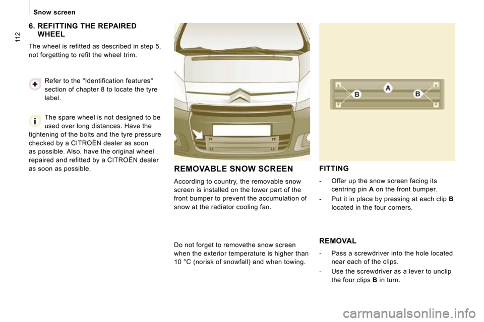
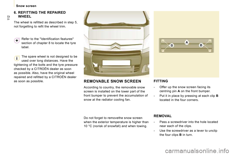
REMOVABLE SNOW SCREEN
According to country, the removable snow
screen is installed on the lower part of the
front bumper to prevent the accumulation of
snow at the radiator cooling fan.
FITTING
- Offer up the snow screen facing its
centring pin A on the front bumper.
- Put it in place by pressing at each clip B
located in the four corners.
Do not forget to remove the snow screen
when the exterior temperature is higher than
10 °C (no risk of snowfall) and when towing. REMOVAL
- Pass a screwdriver into the hole located
near each of the clips.
- Use the screwdriver as a lever to unclip the four clips B in turn.
Page 119 of 225
112
Snow screen
6. REFITTING THE REPAIRED WHEEL
The wheel is refitted as described in step 5,
not forgetting to refit the wheel trim.
The spare wheel is not designed to be
used over long distances. Have the
tightening of the bolts and the tyre pressure
checked by a CITROËN dealer as soon
as possible. Also, have the original wheel
repaired and refitted by a CITROËN dealer
as soon as possible. Refer to the "Identification features"
section of chapter 8 to locate the tyre
label.
REMOVABLE SNOW SCREEN
According to country, the removable snow
screen is installed on the lower part of the
front bumper to prevent the accumulation of
snow at the radiator cooling fan.
FITTING
- Offer up the snow screen facing its
centring pin A on the front bumper.
- Put it in place by pressing at each clip B
located in the four corners.
Do not forget to remove the snow screen
when the exterior temperature is higher than
10 °C (no risk of snowfall) and when towing. REMOVAL
- Pass a screwdriver into the hole located
near each of the clips.
- Use the screwdriver as a lever to unclip the four clips B in turn.
Page 120 of 225
113
Changing a bulb
QUICK HELP
7
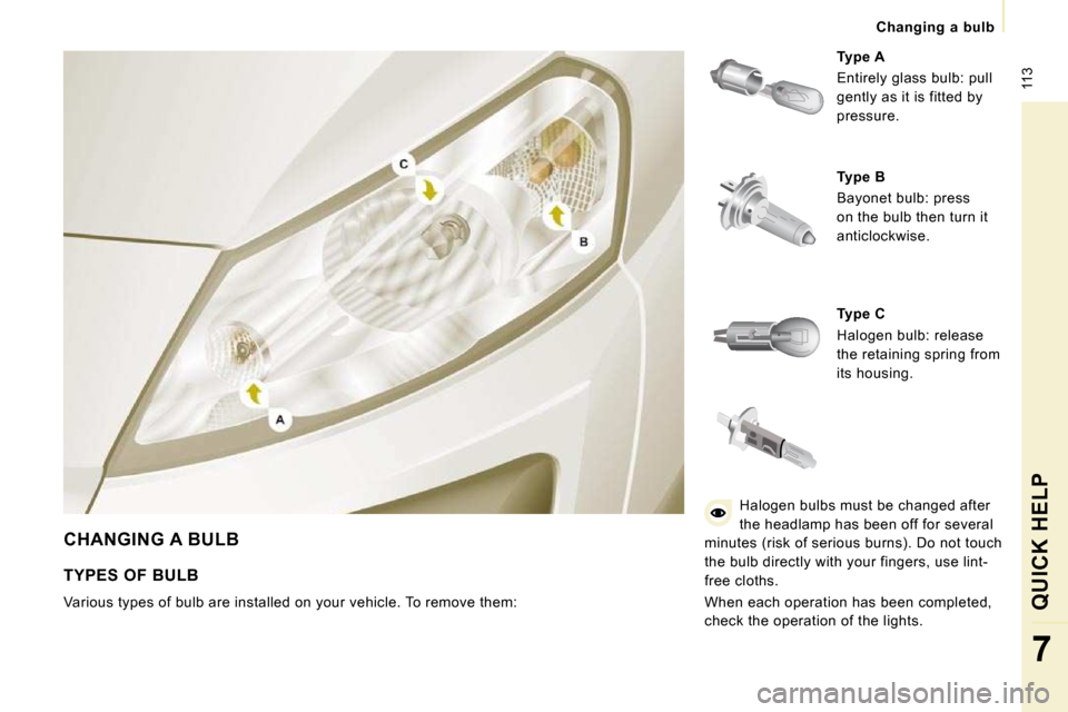
CHANGING A BULB
Type A
Entirely glass bulb: pull
gently as it is fitted by
pressure.
Type B
Bayonet bulb: press
on the bulb then turn it
anticlockwise.
Type C
Halogen bulb: release
the retaining spring from
its housing.
TYPES OF BULB
Various types of bulb are installed on your vehicl e. To remove them: Halogen bulbs must be changed after
the headlamp has been off for several
minutes (risk of serious burns). Do not touch
the bulb directly with your fingers, use lint-
free cloths.
When each operation has been completed,
check the operation of the lights.