Lock CITROEN RELAY 2020 Handbook (in English)
[x] Cancel search | Manufacturer: CITROEN, Model Year: 2020, Model line: RELAY, Model: CITROEN RELAY 2020Pages: 196, PDF Size: 34.07 MB
Page 119 of 196
11 7
In the event of a breakdown
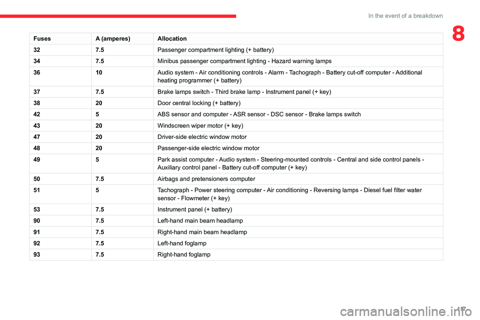
8FusesA (amperes)Allocation
32 7.5Passenger compartment lighting (+ battery)
34 7.5Minibus passenger compartment lighting - Hazard warning lamps
36 10Audio system - Air conditioning controls - Alarm - Tachograph - Battery cut-off computer - Additional
heating programmer (+ battery)
37 7.5Brake lamps switch - Third brake lamp - Instrument panel (+ key)
38 20Door central locking (+ battery)
42 5ABS sensor and computer - ASR sensor - DSC sensor - Brake lamps switch
43 20Windscreen wiper motor (+ key)
47 20Driver-side electric window motor
48 20Passenger-side electric window motor
49 5Park assist computer - Audio system - Steering-mounted controls - Central and side control pane\
ls -
Auxiliary control panel - Battery cut-off computer (+ key)
50 7.5Airbags and pretensioners computer
51 5Tachograph - Power steering computer - Air conditioning - Reversing lamps - Diesel fuel filter water
sensor - Flowmeter (+ key)
53 7.5Instrument panel (+ battery)
90 7.5Left-hand main beam headlamp
91 7.5Right-hand main beam headlamp
92 7.5Left-hand foglamp
93 7.5Right-hand foglamp
Page 123 of 196

121
In the event of a breakdown
8
► Tilt lever 1 downwards to release the
terminals.
► Remove terminals 2 from the negative (-)
terminal.
Wait approximately 6 minutes after
switching off the ignition before
disconnecting the battery.
Do not disconnect the terminals while the
engine is running.
Do not charge a battery without disconnecting
the terminals first.
Close the windows and the doors before
disconnecting the battery.
After reconnecting the battery, turn on the
ignition and wait 1 minute before starting the
engine, to enable the electronic systems to
initialise. If minor problems nevertheless persist
following this operation, contact a CITROËN
dealer or a qualified workshop.
It is recommended to disconnect the (-)
terminal of the battery if the vehicle is to
be left unused for more than one month.
The description of the battery charging
procedure is only indicative.
After prolonged battery disconnection, it may be
necessary to reinitialise the following functions:
– the display parameters (date, time, language,
distance and temperature units),
– the stations of the audio system,
– the central locking.
Some settings are cancelled and must be
entered once again; contact a CITROËN dealer.
If the vehicle is equipped with a tachograph or
an alarm, it is recommended that the (-) terminal
of the battery (located under the floor on the
left-hand side, in the cab) be disconnected if the
vehicle is not going to be used for more than 5
days.
Starting using another
battery
Never start the engine by connecting a
battery charger.
Never use a 24 V or higher battery booster.
Check beforehand that the backup battery
has a nominal voltage of 12 V and a capacity
at least equal to that of the discharged
battery.
The two vehicles must not be in contact with
each other.
Switch off all the electrical consumers on both
vehicles (audio system, wipers, lighting, etc.).
Make sure that the jump leads are not close
to the moving parts of the engine (fan, belt,
etc.).
Do not disconnect the (+) terminal while the
engine is running.
A. Positive metallic terminal of your vehicle
B. Backup battery
C. Earth of your vehicle
The positive metallic terminal A is accessible
through a flap located on the side of the fuse
box.
Connect only to the terminals indicated
and illustrated above. In case of
non-compliance, risk of short circuit!
Page 124 of 196
122
In the event of a breakdown
► Connect the red cable to metallic terminal A,
then to the (+) terminal of backup battery B.
► Connect one end of the green or black cable
to the negative (-) terminal of backup battery B.
► Connect the other end of the green or black
cable to earth point C of your vehicle.
► Operate the starter, let the engine run.
► Wait for the engine to return to idle and
disconnect the cables.
Charging the battery using a
battery charger
► Access the battery, located in the left-hand
front floor.
► Disconnect the battery.
► Follow the instructions for use provided by
the manufacturer of the charger.
► Reconnect starting with the (-) terminal.
► Check the cleanliness of the terminals. If they
are covered with sulphate (whitish or greenish
deposit), remove and clean them.
The charging operation must be carried out in a well-ventilated area and away
from naked flames and any sources of sparks
so as to avoid the risk of explosion or fire.
Do not try to recharge a frozen battery: it
must first be thawed to avoid the risk of
explosion. If it has frozen, before charging it,
have the battery checked by a specialist who
will check that the interior components have
not been damaged and that the container is
not cracked, which would involve a risk of
leakage of toxic and corrosive acid.
Perform a slow charge at low amperage for
about 24 hours maximum to avoid damaging
the battery.
The presence of this label, in particular with the Stop & Start system, indicates
the use of a 12 V lead-acid battery with
special technology and specification; the
involvement of a CITROËN dealer or a
qualified workshop is essential when
replacing or disconnecting the battery.
After refitting the battery at a CITROËN dealer or a qualified workshop, the Stop
& Start system will only be active after a
continuous period of immobilisation of the
vehicle, a period which depends on the
climatic conditions and the state of charge of
the battery (up to about 8 hours).
Towing
General recommendations
Observe the legislation in force in the
country where you are driving.
Ensure that the weight of the towing vehicle is
higher than that of the towed vehicle.
The driver must remain at the wheel of the
towed vehicle and must have a valid driving
licence.
When towing a vehicle with all four wheels on
the ground, always use an approved towing
arm; rope and straps are prohibited.
The towing vehicle must move off gently.
When the vehicle is towed with its engine
off, there is no longer braking and steering
assistance.
A professional towing service must be
called if:
– Broken down on a motorway or main road.
– Not possible to put the gearbox into neutral,
unlock the steering, or release the parking
brake.
– Not possible to tow a vehicle with an
automatic gearbox, with the engine running.
– Towing with only two wheels on the ground.
– Four-wheel drive vehicle.
– No approved towbar available.
Towing your vehicle
The removable towing eye is located in the tool
box under the front passenger seat.
► Unclip the cover using a flat tool.
► Screw the removable towing eye in fully.
► Attach the approved towbar to the removable
towing eye.
► Place the gear lever in neutral.
Page 147 of 196

145
Special features
10Tipper truck
The lifting of the tipper is provided by a hydro-
electric unit powered by the vehicle's battery.
The ascent or descent is done by holding the
corresponding buttons of the magnetic and
removable remote control located on a support
inside the cab.
The lifting of the tipper is powered by unit's
motor.
The descent is powered by a solenoid valve
opening the strut's oil return.
An anti-drop system makes the descent of the
tipper safe whether static or lifting.
Safety recommendations
Never drive with the tail board down.
Ensure that there are no people or
obstacles present (on the ground and higher
up) when unloading.
Never leave the tipper raised when not in use.
Always tip with the upper part of the rear tail
board locked.
Observe the payload on the tare plate on the
vehicle.
Regularly check that the suspensions are in
good condition and that the tyres are inflated
to the recommended pressure.
Spread the load evenly in the tipper.
Transport homogeneous products which flow
easily.
Never drive, even slowly, with the tipper
raised.
Tip on a flat and hard surface: sloping or loose ground can cause a displacement
of the centre of gravity which affects the stability
of the whole unit.
Page 148 of 196

146
Special features
Specifications
EquipmentDetails
Tipper truck Tipper truck bed consisting of 2 high strength steel blanks, 2.5 mm thickness, zinc-coated, joined by central and
longitudinal laser welding.
Body-coloured tipper truck.
Structure of the tipper truck 2 main sidemembers in galvanised high strength steel.
1 ram-head crossmember made of steel tube.
Galvanised high strength steel crossmembers. Assembly protected against corrosion by the application of a
powder paint coating.
Sub-frame 2 “C”-shaped sidemembers in high strength steel, 2.5 mm thickness, secured internally by widened lower wing.
Mounted on base vehicle with high strength steel stamped brackets.
1 ram-foot crossmember made of steel and mechanically-welded tube, hot-dip galvanised.
1 rear hinge crossmember in galvanised steel.
Support stops on sidemember ends.
Rear lamp protection grille.
Truck side guards and wing supports in galvanised steel.
Boards High strength steel boards, 15/10 thickness, cold-formed and assembled by continuous laser welding.
Anti-corrosion protection guaranteed by a powder coating treatment.
Locking handles with reinforced zinc coating, integrated in the recess of the board.
Ladder-carrier Galvanised steel rails. Panels and crossmembers in lacquered steel with crimped bolts.
Electropump unit 12 Volts/2 kW.
Operating temperature: -20 to +70°C.
Hydraulic ram Expansion, nitride rod, 3 bodies, Diam: 107 mm.
Maximum pressure: 20 bar.
Hydraulic oil ISO HV 46 type mineral or equivalent.
Dimensions
This adaptation is available only on L2 single
cab; refer to the table below for the specifications
of the tipper truck.
Tipper truck (in mm)
Useable length 3,200
Overall length 3,248
Useable width 2,000
Overall width 2,100
Height of boards 350
Weight of the conversion (in
kg) 550
For the L2 chassis cab specifications,
refer to the Dimensions section of the
platform version.
Weights and towed loads
(kg)
The braked trailer weight with load transfer can
be increased, provided that the equivalent of this
load is removed from the vehicle so as not to
exceed the GTW. Warning! Towing using a lightly
loaded vehicle can adversely affect roadholding.
The kerb weight is equal to the unladen weight +
driver (75 kg) + tank full to 90%.
Page 150 of 196

148
Special features
– Never work under a tipper body that is not
supported,
– Switch off the power supply to the electro-
hydraulic unit using the circuit breaker,
– Vehicle stationary, engine off.
For safety reasons, we very strongly
advise against doing anything under the
tipper body while it is being operated or while
it is being serviced.
Maintenance
Reservoir
Regularly check and top up the engine oil level.
Change the oil once a year. If the oil contains
water, change it.
Regularly check the condition of the hose and
ensure the hydraulic system is properly sealed.
Pump and motor
No servicing required. The rolling elements are
permanently lubricated and the bearings are
lubricated by the pumped oil.
Lubrication
The pins of the tipper truck and the ram do not
contain lubricant. Regularly lubricate the hinges
and the grab handles of the side boards as well
as the retaining hooks of the rear board.
Sub-frame and tipper truck
For maximum service life, you are advised to
maintain your tipper truck by regularly washing it
using a power washer.
Carry out any required paint touch-ups quickly to
prevent the spread of rust.
After 8 months of use, check the tightening torque of the connection
between the chassis and the underbody (in
accordance with the manufacturer's
bodybuilding recommendations).
Cleaning the slide valve
► Loosen cap 244A, taking care with the ball
and retrieving it.
► Using a wide screwdriver, unscrew the banjo
bolt/piston assembly.
► Check that the piston slides freely and
remove any foreign bodies. Use a magnet to
remove any metal filings.
► Refit the assembly and make sure that the
piston slides freely. Retain the ball with a little
grease on the cap for refitting.
► Bleed the hydraulic unit.
Bleeding the hydraulic unit
► Unscrew hexagonal cap 257.
► Loosen internal screw 587 by half a turn,
using a 6 mm hex key.
► Operate the unit for a few seconds by
pressing the raise button.
The tipper truck does not rise or rises very
slowly. When the oil exits through this opening,
the unit is bled.
► Retighten screw 587 and replace cap 257.
Check that the tipper truck lowers correctly.
Detailed diagram of the UD2386 hydraulic
unit
Diagnostics
Symptoms ElectricHydraulic Verification/Check
The hydraulic unit does not work. XPower harness and unit relay.
X Control harness (control unit).
X Circuit-breaker.
Very noisy unit, rises slowly. XSuction strainer clogged or crushed at the bottom of the tank.
Very noisy new unit, rises quickly. XPump alignment, change the unit.
The ram lowers by itself. XLowering valve crushed or blocked.
The ram does not lower. XYes, check the slide valve and bleed.
Refer to the "Maintenance" section.
X No, check the coil and the electrical connections of the valve.
X No, replace the solenoid valve.
X No, check the alignment of the ram.
The unit works but its pressure does
not increase. X
Slide valve jammed if no solenoid valve on the unit.
Refer to the "Maintenance" section.
X Pressure relief device, setting, dirt.
X Pump seal out of service.
X Motor/pump coupling.
X Pump loose from its support.
The hydraulic unit does not work. XSolenoid valve blocked, replace it or retighten the nut behind the strainer .
The control unit does not work. XCheck connection and contacts.
Emulsion in the tank. XIncorrectly positioned return pipe.
X Insufficient oil level.
Page 151 of 196

149
Special features
10Diagnostics
SymptomsElectricHydraulic Verification/Check
The hydraulic unit does not work. XPower harness and unit relay.
X Control harness (control unit).
X Circuit-breaker.
Very noisy unit, rises slowly. XSuction strainer clogged or crushed at the bottom of the tank.
Very noisy new unit, rises quickly. XPump alignment, change the unit.
The ram lowers by itself. XLowering valve crushed or blocked.
The ram does not lower. XYes, check the slide valve and bleed.
Refer to the "Maintenance" section.
X No, check the coil and the electrical connections of the valve.
X No, replace the solenoid valve.
X No, check the alignment of the ram.
The unit works but its pressure does
not increase. X
Slide valve jammed if no solenoid valve on the unit.
Refer to the "Maintenance" section.
X Pressure relief device, setting, dirt.
X Pump seal out of service.
X Motor/pump coupling.
X Pump loose from its support.
The hydraulic unit does not work. XSolenoid valve blocked, replace it or retighten the nut behind the strainer .
The control unit does not work. XCheck connection and contacts.
Emulsion in the tank. XIncorrectly positioned return pipe.
X Insufficient oil level.
Page 154 of 196
152
Audio system
To protect the system, do not use a USB hub.
The system builds playlists (in temporary
memory); this operation can take from a
few seconds to several minutes at the first
connection.
Reduce the number of non-music files and the
number of folders to reduce the waiting time.
The playlists are updated every time the ignition
is switched off or a USB memory stick is
connected. The lists are memorised: if they are
not modified, the subsequent loading time will
be shorter.
USB socket
Located on the central console, this
socket is used only to power and
recharge the connected portable device.
Auxiliary socket (AUX)
Connect a portable device (MP3 player,
etc.) to the auxiliary jack socket using an
audio cable (not supplied).
First adjust the volume on your portable device
(to a high level). Then adjust the volume on your
audio system.
Controls are managed via the portable device.
The functions of the device connected to the
“AUX” socket are managed directly by this
device: it is therefore not possible to change the
track/folder/playlist or manipulate the playback
Radio, toggle up or down continuously: scan up/
down frequencies until you release the button.
Media, toggle up or down: select next/previous
track.
Media, toggle up or down continuously: fast
forward/rewind until you release the button.
Refuse an incoming call.
End the call in progress.
Radio
Selecting a station
The exterior environment (hills, buildings, tunnels, car parks, underground location,
etc.) may block reception, including in RDS
mode.
This behaviour is normal in the propagation of
radio waves and does not indicate any fault
with the audio system.
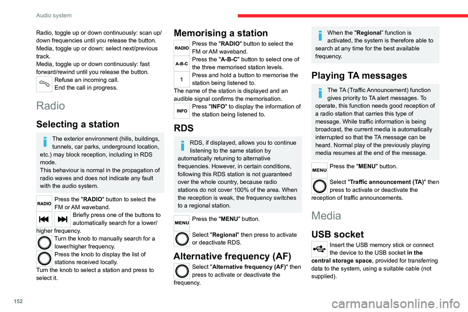
Press the "RADIO" button to select the
FM or AM waveband.
Briefly press one of the buttons to
automatically search for a lower/
higher frequency.
Turn the knob to manually search for a lower/higher frequency.
Press the knob to display the list of
stations received locally.
Turn the knob to select a station and press to
select it.
Memorising a station
Press the "RADIO" button to select the
FM or AM waveband.
Press the "A-B-C" button to select one of
the three memorised station levels.
Press and hold a button to memorise the
station being listened to.
The name of the station is displayed and an
audible signal confirms the memorisation.
Press "INFO" to display the information of
the station being listened to.
RDS
RDS, if displayed, allows you to continue
listening to the same station by
automatically retuning to alternative
frequencies. However, in certain conditions,
following this RDS station is not guaranteed
over the whole country, because radio
stations do not cover 100% of the area. When
the reception is weak, the frequency switches
to a regional station.
Press the "MENU" button.
Select "Regional" then press to activate
or deactivate RDS.
Alternative frequency (AF)
Select "Alternative frequency (AF)" then
press to activate or deactivate the
frequency.
When the "Regional” function is
activated, the system is therefore able to
search at any time for the best available
frequency.
Playing TA messages
The TA (Traffic Announcement) function gives priority to TA alert messages. To
operate, this function needs good reception of
a radio station that carries this type of
message. While traffic information is being
broadcast, the current media is automatically
interrupted so that the TA message can be
heard. Normal play of the previously playing
media resumes at the end of the message.
Press the "MENU" button.
Select "Traffic announcement (TA)" then
press to activate or deactivate the
reception of traffic announcements.
Media
USB socket
Insert the USB memory stick or connect
the device to the USB socket in the
central storage space , provided for transferring
data to the system, using a suitable cable (not
supplied).
Page 162 of 196
160
Touch screen audio and telematics system
Vehicle information
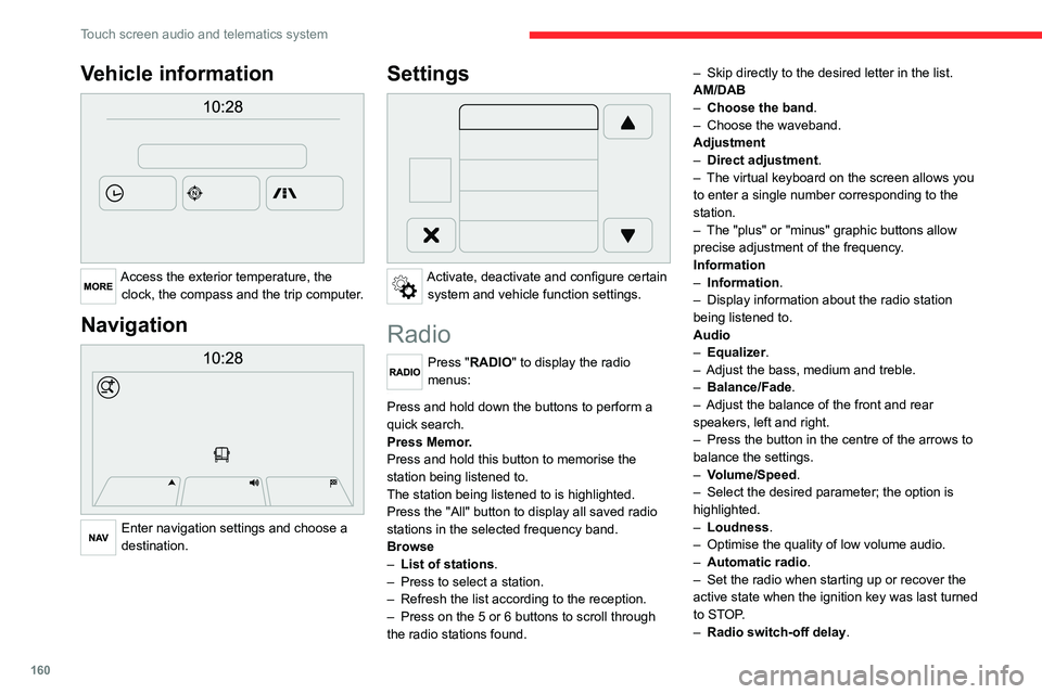
Access the exterior temperature, the clock, the compass and the trip computer.
Navigation
Enter navigation settings and choose a
destination.
Settings
Activate, deactivate and configure certain system and vehicle function settings.
Radio
Press "RADIO" to display the radio
menus:
Briefly press on the 9 or : buttons to perform an automatic search.
Press and hold down the buttons to perform a
quick search.
Press Memor.
Press and hold this button to memorise the
station being listened to.
The station being listened to is highlighted.
Press the "All" button to display all saved radio
stations in the selected frequency band.
Browse
– List of stations .
– Press to select a station.
– Refresh the list according to the reception.
– Press on the 5 or 6 buttons to scroll through
the radio stations found. –
Skip directly to the desired letter in the list.
AM/DAB
– Choose the band .
– Choose the waveband.
Adjustment
– Direct adjustment.
– The virtual keyboard on the screen allows you
to enter a single number corresponding to the
station.
– The "plus" or "minus" graphic buttons allow
precise adjustment of the frequency.
Information
– Information .
– Display information about the radio station
being listened to.
Audio
– Equalizer.
– Adjust the bass, medium and treble.
– Balance/Fade.
– Adjust the balance of the front and rear
speakers, left and right.
– Press the button in the centre of the arrows to
balance the settings.
– Volume/Speed.
– Select the desired parameter; the option is
highlighted.
– Loudness.
– Optimise the quality of low volume audio.
– Automatic radio.
– Set the radio when starting up or recover the
active state when the ignition key was last turned
to STOP.
– Radio switch-off delay .
– Set the parameter.
– AUX vol. setting .
– Set the parameters.
DAB (Digital Audio
Broadcasting) radio
Terrestrial Digital Radio
Digital radio
Digital radio provides higher quality
reception and also the graphical display
of current information on the radio station
being listened to.
The various "multiplexes/ensembles" offer
a choice of radio stations organised in
alphabetical order.
Press “RADIO” successively to display
the "DAB Radio".
Select the "Navigate" tab.
Select a list from the filters
offered: "All", "Types",
"Ensembles", then select a radio station.
Press the "Update" button to update the
list of "DAB Radio" stations received.
Page 166 of 196
164
Touch screen audio and telematics system
Change the appearance and behaviour of the
navigation system.
Most system settings can be accessed by
touching "Settings" in the main menu.
Help
Access information about assistance services
and other specialised services.
Finish
Validate the settings.
Limitation
Speed limitation (if known).
To see the difference between the desired arrival
time and the estimated arrival time.
Switch between a 3D map and a 2D map.
Go to..., Display the map, Plan a route,
Services, Settings, Help, Finish.
When the navigation system starts for the first
time, the "Driving mode" as well as detailed
information on the current position is displayed.
Touch the centre of the screen to open the main
menu.
Details
The route summary provides an overview of the
route, the remaining distance to the destination
and an estimate of the remaining travel time.
With the RDS-TMC data, the route summary
also shows the traffic information concerning
delays along the route.
Modify route
The navigation system helps you to get to your
destination as quickly as possible by displaying a
faster alternative route when it is available.
FinishValidate the settings.
Instructions
Navigation instructions for the next part of the
trip and the distance to the next instruction. If the
second instruction is less than 150 metres from
the first one, it is immediately displayed instead
of the distance.
Touch this part of the status bar to repeat the last
voice instruction.
Updating maps
To get a map update, you can proceed as follows:
– Map refresh guarantee: if a new map
becomes available within 90 days of the first
use of the system, you can download it once
for free.
– Map update: you can buy a new version of
your system’s map.
To install a map update on your system, perform
the following four steps:
– Prepare a USB device.
– Install TomTom HOME and create a
MyTomTom account.
– Download the map.
– Install the new map.
Use a USB device instead of a mass
storage device (telephone or media
player).
To protect the system, do not use a USB hub.
Prepare a USB device
The preparation of the USB device
must be done with the engine running
and the vehicle stationary.
In order to update the map, you must have
a USB device that meets the following
requirements:
– The USB device must be empty.
– The USB device has 16 GB of available
space.
– Use only USB devices in FAT32 format (File
Allocation Table).
– Do not lock the USB device and check that
files can be saved on it.
To prepare the USB device, proceed as follows:
► Make sure that the map you want to update is
active on your navigation system.
If the navigation system has multiple maps and
you want to update a map that is not currently
active, start by activating it.
► Select “Change map” in the “Settings” menu
of the navigation application.
► Select “Navigation updates” from the
“Settings” menu.
► You must indicate whether you want to
prepare a USB device to download updates.
► Select "Ye s ".