engine Citroen XSARA PICASSO 2005 1.G Workshop Manual
[x] Cancel search | Manufacturer: CITROEN, Model Year: 2005, Model line: XSARA PICASSO, Model: Citroen XSARA PICASSO 2005 1.GPages: 462, PDF Size: 10.48 MB
Page 381 of 462
Downloaded from www.Manualslib.com manuals search engine 375
AXLES
SUSPENSION
STEERING
XSARA AXLE GEOMETRY
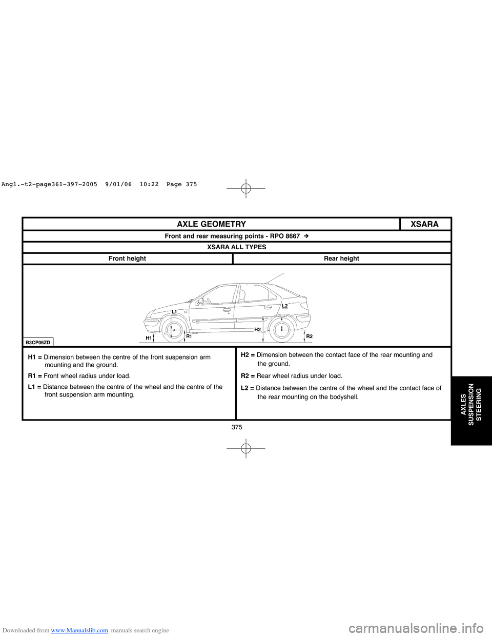
Front and rear measuring points - RPO 8667 #
XSARA ALL TYPES
Front height
Rear height
H1 = Dimension between the centre of the front suspension arm
mounting and the ground.
R1 =Front wheel radius under load.
L1 =Distance between the centre of the wheel and the centre of the
front suspension arm mounting.
B3CP06ZD
H2 = Dimension between the contact face of the rear mounting and
the ground.
R2 =Rear wheel radius under load.
L2 =Distance between the centre of the wheel and the contact face of
the rear mounting on the bodyshell.
Angl.-t2-page361-397-2005 9/01/06 10:22 Page 375
Page 382 of 462
Downloaded from www.Manualslib.com manuals search engine 376
AXLES
SUSPENSION
STEERING
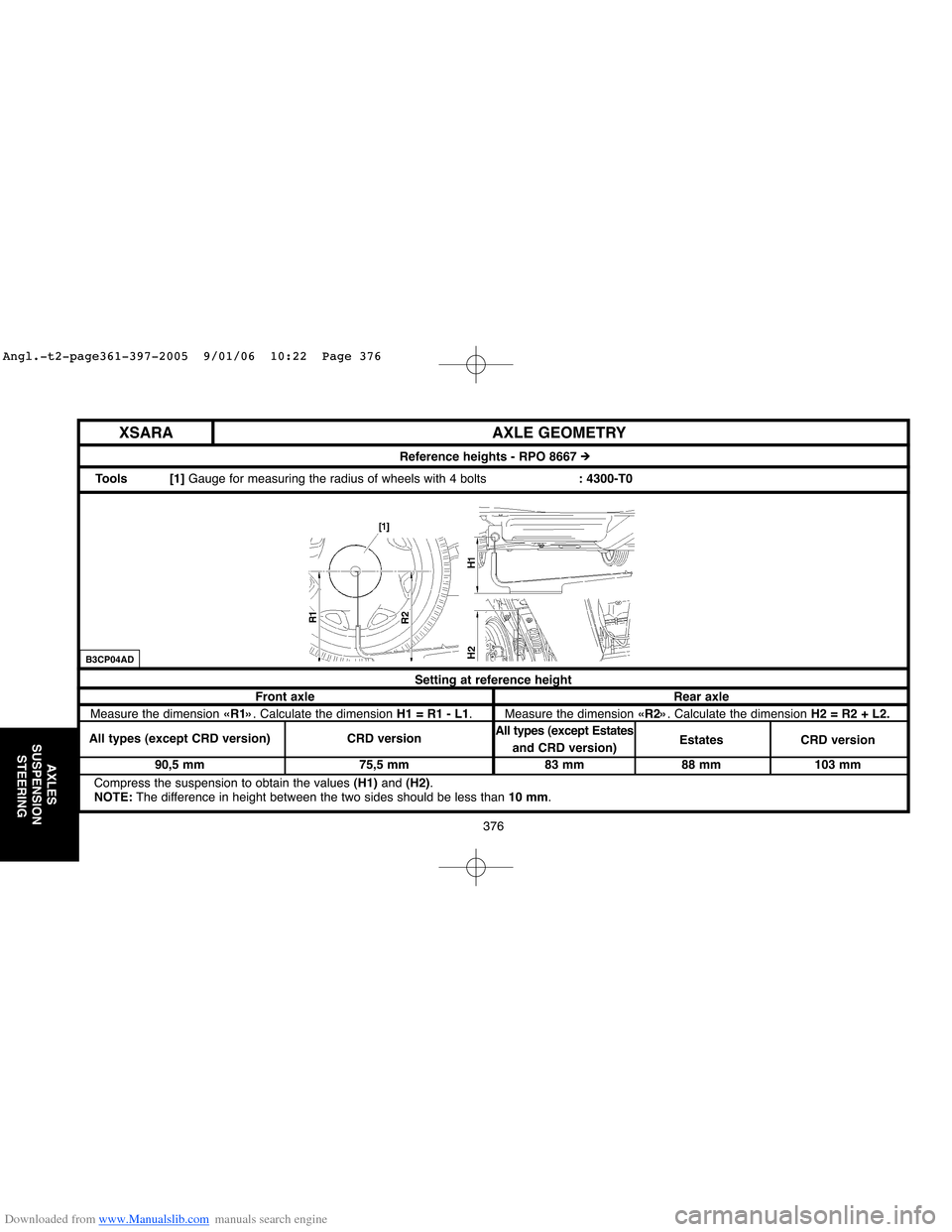
Setting at reference height
Front axle Rear axle
Measure the dimension «R1». Calculate the dimension H1 = R1 - L1. Measure the dimension «R2». Calculate the dimension H2 = R2 + L2.
All types (except CRD version) CRD versionAll types (except Estates
and CRD version) Estates CRD version
90,5 mm 75,5 mm 83 mm 88 mm 103 mm
Compress the suspension to obtain the values (H1)and (H2).
NOTE:The difference in height between the two sides should be less than 10 mm.
AXLE GEOMETRY
Reference heights - RPO 8667 #
Tools [1] Gauge for measuring the radius of wheels with 4 bolts: 4300-T0
XSARA
B3CP04AD
Angl.-t2-page361-397-2005 9/01/06 10:22 Page 376
Page 383 of 462
Downloaded from www.Manualslib.com manuals search engine 377
AXLES
SUSPENSION
STEERING
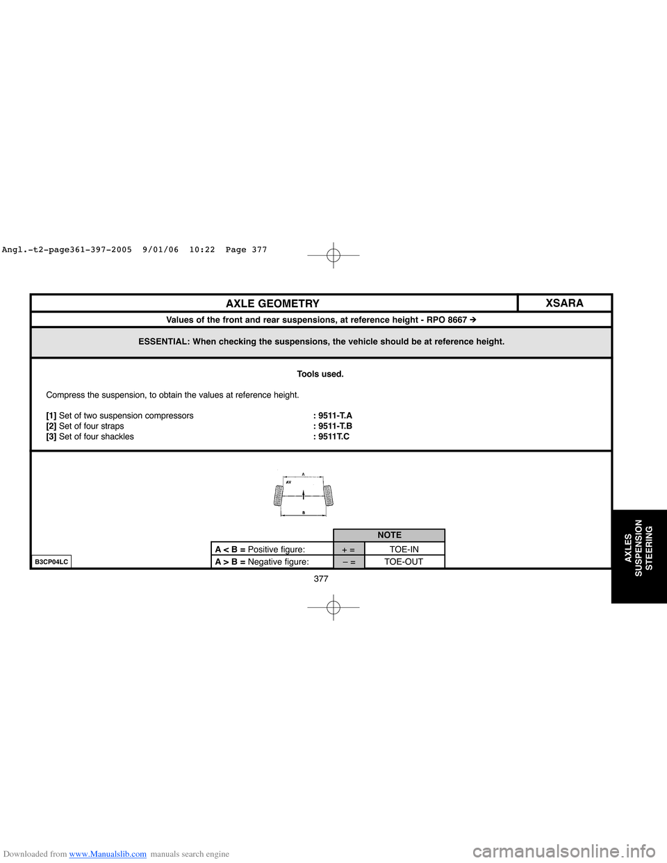
ESSENTIAL: When checking the suspensions, the vehicle should be at reference height.
XSARA
AXLE GEOMETRY
Values of the front and rear suspensions, at reference height - RPO 8667 #
Tools used.
Compress the suspension, to obtain the values at reference height.
[1]Set of two suspension compressors: 9511-T.A
[2]Set of four straps: 9511-T.B
[3] Set of four shackles: 9511T.C
A> B =Negative figure: – = TOE-OUT A < B = Positive figure: + = TOE-INNOTE
B3CP04LC
Angl.-t2-page361-397-2005 9/01/06 10:22 Page 377
Page 384 of 462
Downloaded from www.Manualslib.com manuals search engine 378
AXLES
SUSPENSION
STEERING
AXLE GEOMETRY XSARA
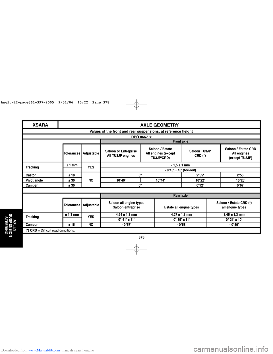
Values of the front and rear suspensions, at reference height
RPO 8667 #Front axle
Saloon / Estate
Saloon or Entreprise
All engines (exceptSaloon TU3JPSaloon / Estate CRD
Tolerances Adjustable
All TU3JP engines
TU3JP/CRD)CRD (*)All engines
(except TU3JP)
Tracking±1 mm
YES- 1,5 ± 1 mm
- 0°15' ± 10' (toe-out)
Castor ± 18' 3° 2°55' 2°55'
Pivot angle ± 30' NO 10°40' 10°44' 10°22' 10°26'
Camber ± 30' 0° 0°12' 0°07'
Rear axle
Saloon / Estate CRD (*)
Tolerances AdjustableSaloon all engine types
Estate all engine types all engine types Saloon entreprise
Tracking± 1,3 mm
YES4,54 ± 1,3 mm 4,27 ± 1,3 mm 3,45 ± 1,3 mm
0° 41' ± 11' 0° 39' ± 11' 0° 31' ± 10'
Camber ± 15' NO - 0°57' - 0°58' - 0°59'
(*) CRD = Difficult road conditions.
Angl.-t2-page361-397-2005 9/01/06 10:22 Page 378
Page 385 of 462
Downloaded from www.Manualslib.com manuals search engine 379
AXLES
SUSPENSION
STEERING
XSARA
AXLE GEOMETRY
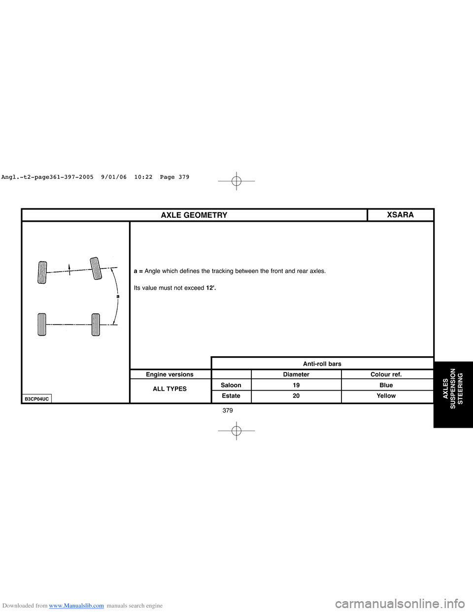
a = Angle which defines the tracking between the front and rear axles.
Its value must not exceed12'.
Anti-roll bars
Engine versions Diameter Colour ref.
ALL TYPESSaloon 19 Blue
Estate 20 Yellow
B3CP04UC
Angl.-t2-page361-397-2005 9/01/06 10:22 Page 379
Page 386 of 462
Downloaded from www.Manualslib.com manuals search engine 380
AXLES
SUSPENSION
STEERING
XSARA TIGHTENING TORQUES: FRONT AXLE
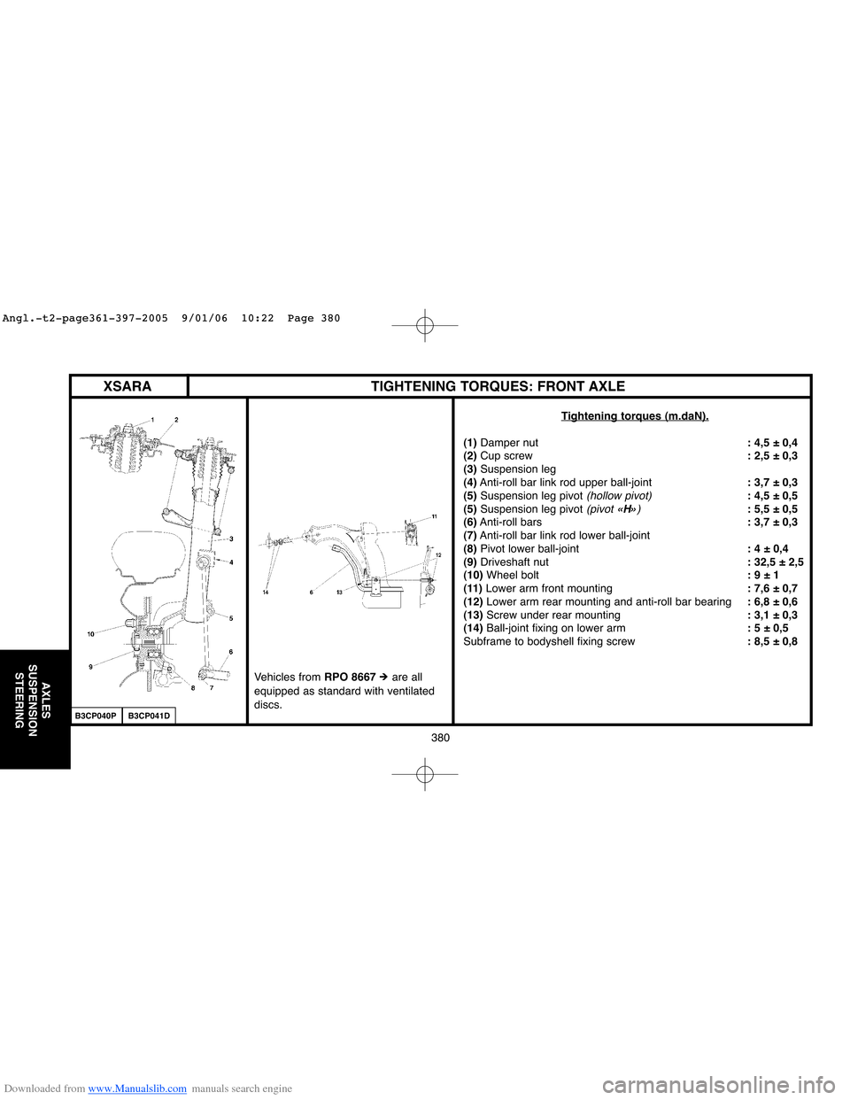
Tightening torques (m.daN).
(1)Damper nut: 4,5 ± 0,4
(2)Cup screw: 2,5 ± 0,3
(3)Suspension leg
(4)Anti-roll bar link rod upper ball-joint: 3,7 ± 0,3
(5)Suspension leg pivot
(hollow pivot): 4,5 ± 0,5
(5)Suspension leg pivot (pivot «H»): 5,5 ± 0,5
(6)Anti-roll bars: 3,7 ± 0,3
(7)Anti-roll bar link rod lower ball-joint
(8)Pivot lower ball-joint: 4 ± 0,4
(9) Driveshaft nut: 32,5 ± 2,5
(10)Wheel bolt: 9 ± 1
(11) Lower arm front mounting: 7,6 ± 0,7
(12)Lower arm rear mounting and anti-roll bar bearing: 6,8 ± 0,6
(13)Screw under rear mounting: 3,1 ± 0,3
(14) Ball-joint fixing on lower arm: 5 ± 0,5
Subframe to bodyshell fixing screw: 8,5 ± 0,8
B3CP040PB3CP041D
Vehicles from RPO 8667# are all
equipped as standard with ventilated
discs.
Angl.-t2-page361-397-2005 9/01/06 10:22 Page 380
Page 387 of 462

Downloaded from www.Manualslib.com manuals search engine 381
AXLES
SUSPENSION
STEERING
XSARA REAR AXLE
- The frontsilentblocks are aligned at an angle of 45°in relation to the vehicle's axis.
- The rearsilentblocks are in parallel with the vehicle's axis.
NOTE:There are two suppliers for the silentblocks:
- RBT, identified by a Greenor Yellowpainted dot on the side of the mounting.
- PAULSTRA, identified by a Blackpainted dot on the side of the mounting.
It is FORBIDDENto swap components of different suppliers. Operating clearance - X = 1 to 1.4 mm.
NOTE: The RH torsion bar can be identified
by 1 paint line.
The LH torsion bar can be identified by2 paint
lines.
B3DP04UDB3DP04TC
Angl.-t2-page361-397-2005 9/01/06 10:22 Page 381
Page 388 of 462
Downloaded from www.Manualslib.com manuals search engine 382
AXLES
SUSPENSION
STEERING
XSARA TIGHTENING TORQUES: REAR AXLE
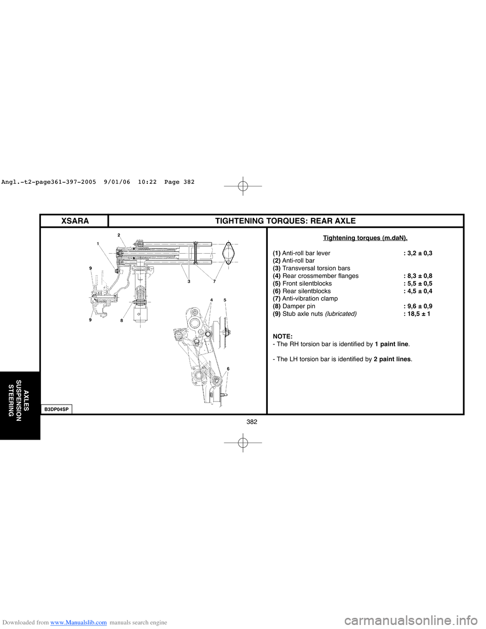
Tightening torques (m.daN).
(1)Anti-roll bar lever: 3,2 ± 0,3
(2)Anti-roll bar
(3)Transversal torsion bars
(4)Rear crossmember flanges: 8,3 ± 0,8
(5)Front silentblocks: 5,5 ± 0,5
(6) Rear silentblocks: 4,5 ± 0,4
(7)Anti-vibration clamp
(8)Damper pin: 9,6 ± 0,9
(9)Stub axle nuts
(lubricated): 18,5 ± 1
NOTE:
- The RH torsion bar is identified by 1 paint line.
- The LH torsion bar is identified by 2 paint lines.
B3DP04SP
Angl.-t2-page361-397-2005 9/01/06 10:22 Page 382
Page 389 of 462
Downloaded from www.Manualslib.com manuals search engine 383
AXLES
SUSPENSION
STEERING
XSARA
Steering wheel - Manual steering
TIGHTENING TORQUES: MANUAL STEERING
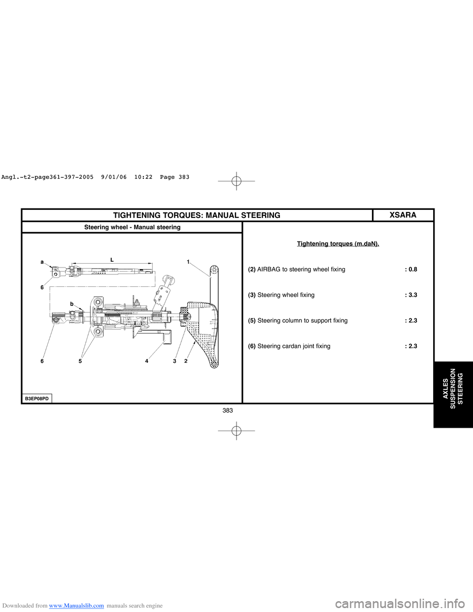
Tightening torques (m.daN).
(2)AIRBAG to steering wheel fixing: 0.8
(3)Steering wheel fixing: 3.3
(5)Steering column to support fixing: 2.3
(6)Steering cardan joint fixing: 2.3
B3EP08PD
Angl.-t2-page361-397-2005 9/01/06 10:22 Page 383
Page 390 of 462

Downloaded from www.Manualslib.com manuals search engine 384
AXLES
SUSPENSION
STEERING
XSARATIGHTENING TORQUES: MANUAL STEERING
Manual steering
Tightening torques (m.daN).
(7)Pivot ball-joint nut: 4
(8)Link rod lock nut :4.5
(9) Ball-joint on steering rack: 6
(10)Fixing on cradle : 5
(11)Plunger flange screws : 1.2
B3EP042D
Angl.-t2-page361-397-2005 9/01/06 10:22 Page 384