engine Citroen XSARA PICASSO 2005 1.G Workshop Manual
[x] Cancel search | Manufacturer: CITROEN, Model Year: 2005, Model line: XSARA PICASSO, Model: Citroen XSARA PICASSO 2005 1.GPages: 462, PDF Size: 10.48 MB
Page 361 of 462
Downloaded from www.Manualslib.com manuals search engine 355
CLUTCH
GEARBOX
TRANSMISSION
AL4 GEARBOX CONTROLS
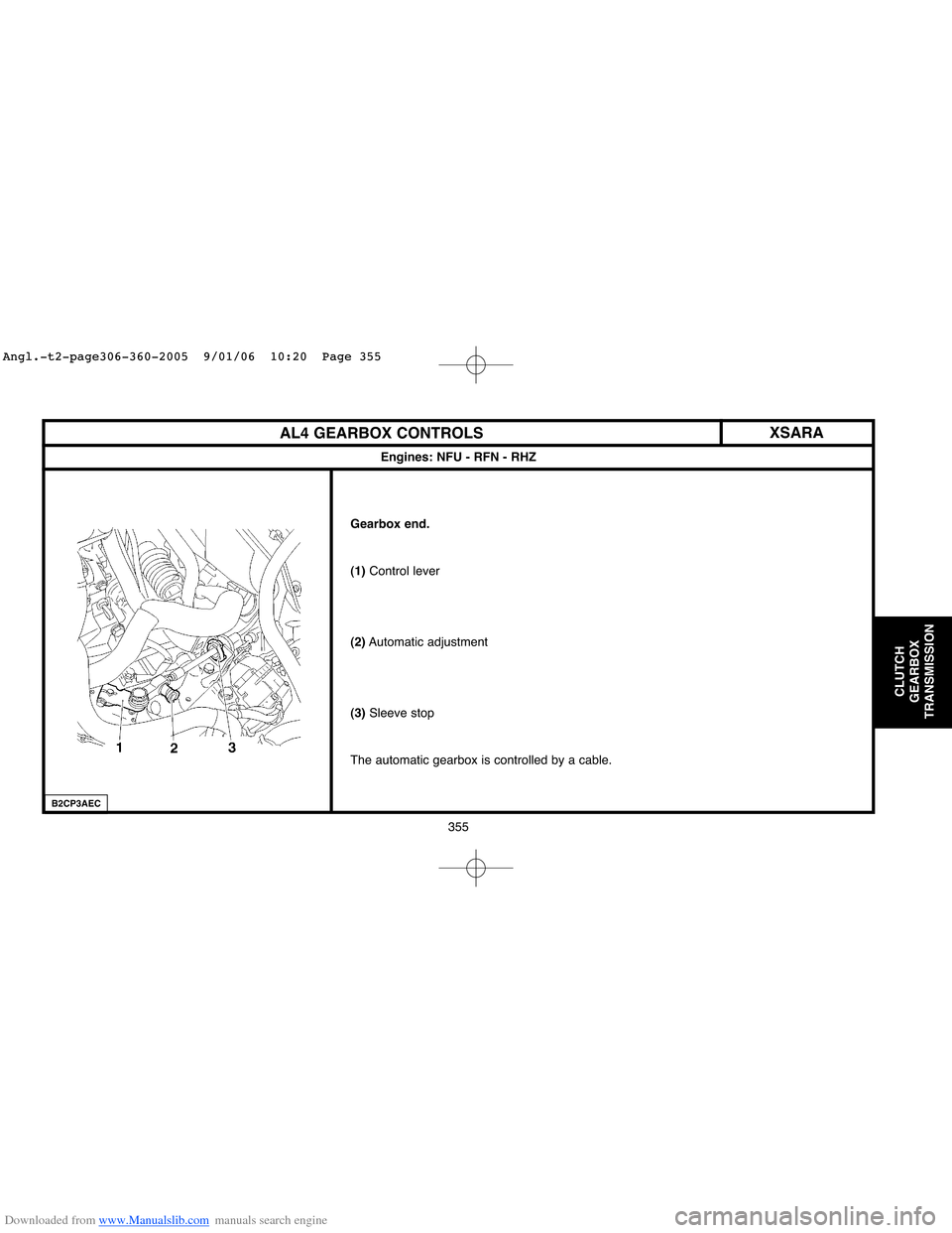
Gearbox end.
(1)Control lever
(2)Automatic adjustment
(3)Sleeve stop
The automatic gearbox is controlled by a cable.
Engines: NFU - RFN - RHZ
XSARA
B2CP3AEC
Angl.-t2-page306-360-2005 9/01/06 10:20 Page 355
Page 362 of 462
Downloaded from www.Manualslib.com manuals search engine 356
CLUTCH
GEARBOX
TRANSMISSION
AL4 GEARBOX CONTROLS
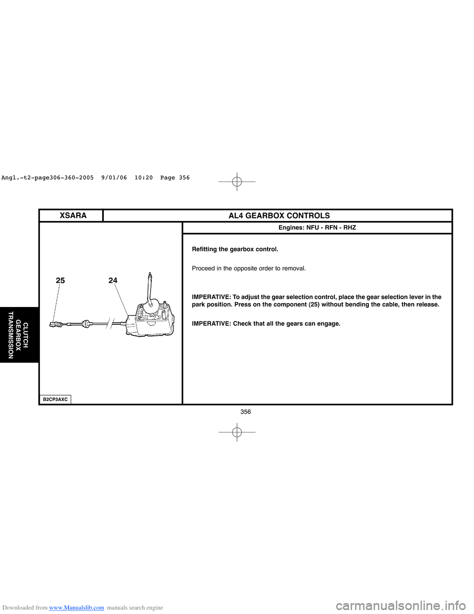
Refitting the gearbox control.
Proceed in the opposite order to removal.
IMPERATIVE: To adjust the gear selection control, place the gear selection lever in the
park position. Press on the component (25) without bending the cable, then release.
IMPERATIVE: Check that all the gears can engage.
Engines: NFU - RFN - RHZ
XSARA
B2CP3AXC
Angl.-t2-page306-360-2005 9/01/06 10:20 Page 356
Page 363 of 462
Downloaded from www.Manualslib.com manuals search engine 357
CLUTCH
GEARBOX
TRANSMISSION
XSARARECOMMENDATIONS/PRECAUTIONS: AL4 AUTOMATIC GEARBOX (SHIFT LOCK)
Engines: NFU - RFN - RHZ
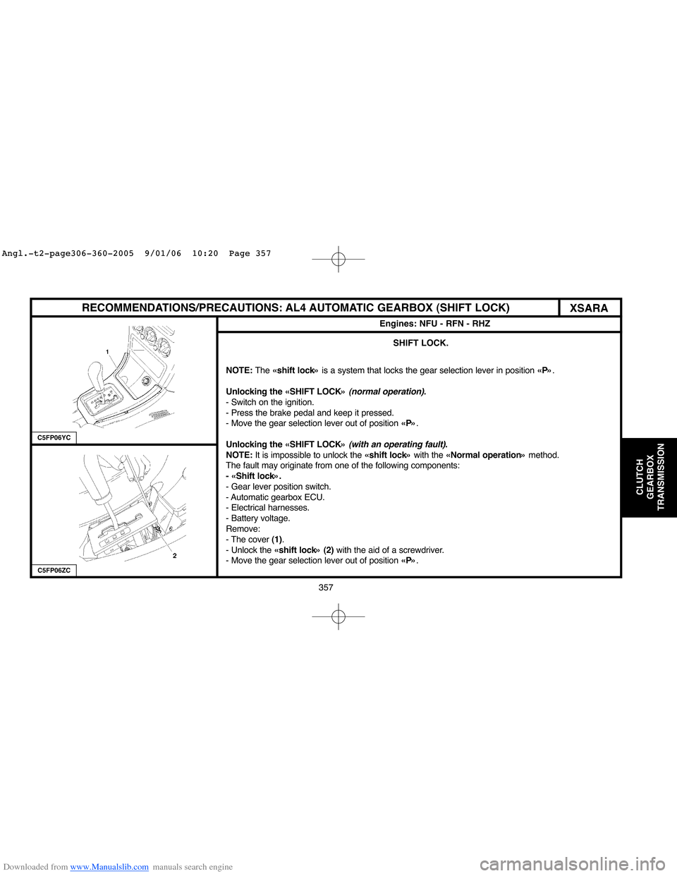
SHIFT LOCK.
NOTE: The«shift lock» is a system that locks the gear selection lever in position«P».
Unlocking the «SHIFT LOCK»
(normal operation).
- Switch on the ignition.
- Press the brake pedal and keep it pressed.
- Move the gear selection lever out of position«P».
Unlocking the «SHIFT LOCK»
(with an operating fault).
NOTE: It is impossible to unlock the«shift lock» with the«Normal operation» method.
The fault may originate from one of the following components:
- «Shift lock».
- Gear lever position switch.
- Automatic gearbox ECU.
- Electrical harnesses.
- Battery voltage.
Remove:
- The cover(1).
- Unlock the«shift lock» (2) with the aid of a screwdriver.
- Move the gear selection lever out of position«P».
C5FP06ZC
C5FP06YC
Angl.-t2-page306-360-2005 9/01/06 10:20 Page 357
Page 364 of 462
Downloaded from www.Manualslib.com manuals search engine 358
CLUTCH
GEARBOX
TRANSMISSION
RECOMMENDATIONS/PRECAUTIONS: AL4 AUTOMATIC GEARBOX (SHIFT LOCK)
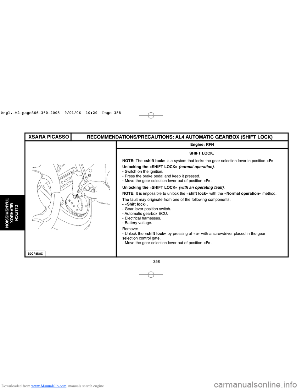
SHIFT LOCK.
NOTE: The«shift lock» is a system that locks the gear selection lever in position«P».
Unlocking the «SHIFT LOCK»
(normal operation).
- Switch on the ignition.
- Press the brake pedal and keep it pressed.
- Move the gear selection lever out of position«P».
Unlocking the «SHIFT LOCK»
(with an operating fault).
NOTE:It is impossible to unlock the«shift lock» with the«Normal operation» method.
The fault may originate from one of the following components:
- «Shift lock».
- Gear lever position switch.
- Automatic gearbox ECU.
- Electrical harnesses.
- Battery voltage.
Remove:
- Unlock the«shift lock» by pressing at «a» with a screwdriver placed in the gear
selection control gate.
- Move the gear selection lever out of position«P».
Engine: RFN
XSARA PICASSO
B2CP3N8C
Angl.-t2-page306-360-2005 9/01/06 10:20 Page 358
Page 365 of 462
Downloaded from www.Manualslib.com manuals search engine 359
CLUTCH
GEARBOX
TRANSMISSION
AL4 GEARBOX CONTROLS
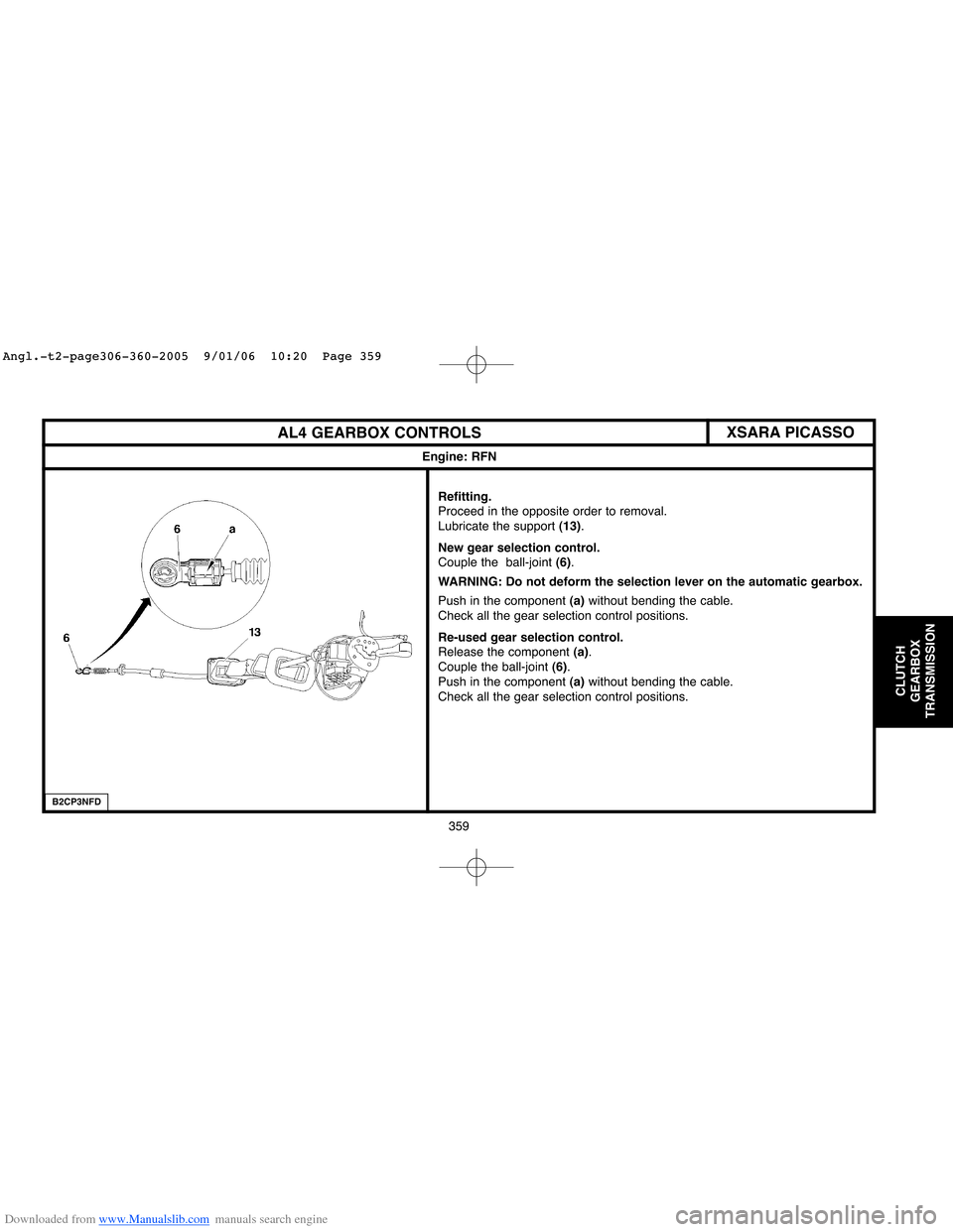
Refitting.
Proceed in the opposite order to removal.
Lubricate the support (13).
New gear selection control.
Couple the ball-joint (6).
WARNING: Do not deform the selection lever on the automatic gearbox.
Push in the component (a)without bending the cable.
Check all the gear selection control positions.
Re-used gear selection control.
Release the component (a).
Couple the ball-joint (6).
Push in the component (a)without bending the cable.
Check all the gear selection control positions.
Engine: RFN
XSARA PICASSO
B2CP3NFD
Angl.-t2-page306-360-2005 9/01/06 10:20 Page 359
Page 366 of 462
Downloaded from www.Manualslib.com manuals search engine 360
CLUTCH
GEARBOX
TRANSMISSION
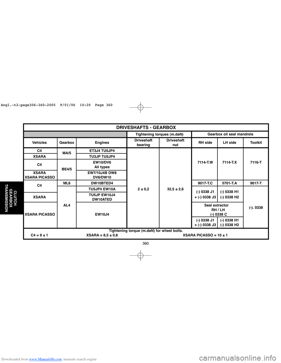
DRIVESHAFTS - GEARBOX
Tightening torques (m.daN)Gearbox oil seal mandrels
Vehicles GearboxDriveshaft Driveshaft
Engines
bearing nutRH side LH side Toolkit
C4
MA/5ET3J4 TU5JP4
XSARA TU3JP TU5JP4
C4EW10/DV6 7114-T.W 7114-T.X 7116-T
BE4/5All types
XSARA EW7/10J4B DW8
XSARA PICASSO DV6/DW10
C4ML6 DW10BTED4 9017-T.C 5701-T.A 9017-T
TU5JP4 EW10A 2 ± 0,2 32,5 ± 2,6
(-) 0338 J1 (-) 0338 H1
XSARATU5JP EW10J4
+ (-) 0338 J3 (-) 0338 H2
DW10ATED
AL4Seal extractor
RH / LH(-). 0338
XSARA PICASSO EW10J4 (-) 0338 C
(-) 0338 J1 (-) 0338 H1
+ (-) 0338 J3 (-) 0338 H2
Tightening torque (m.daN) for wheel bolts.
C4 = 9 ± 1 XSARA = 8,5 ± 0,8 XSARA PICASSO = 10 ± 1
Angl.-t2-page306-360-2005 9/01/06 10:20 Page 360
Page 367 of 462
Downloaded from www.Manualslib.com manuals search engine 361
AXLES
SUSPENSION
STEERING
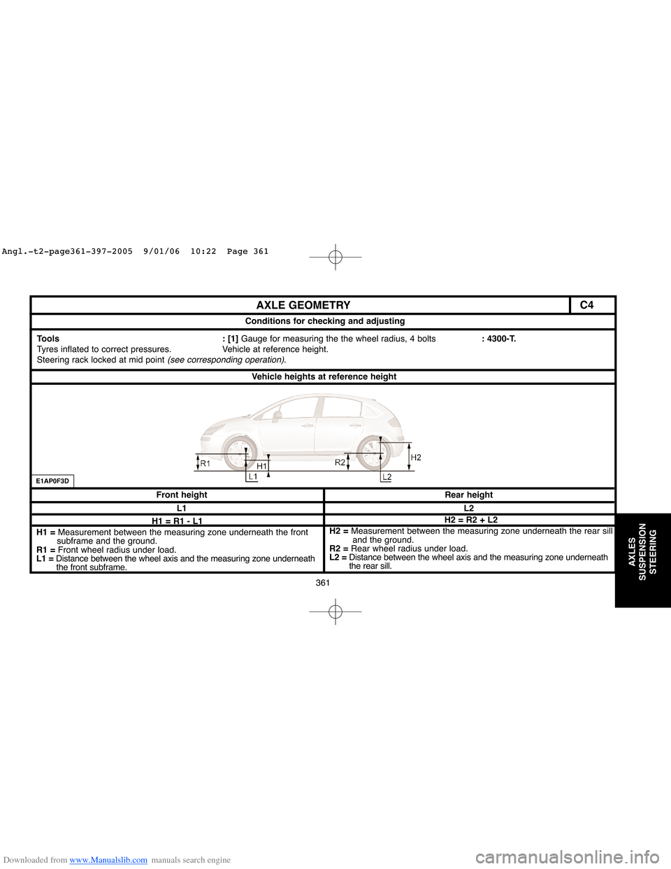
AXLE GEOMETRY
Conditions for checking and adjusting
Vehicle heights at reference height
Rear height Front height
L2 L1
Tools : [1] Gauge for measuring the the wheel radius, 4 bolts: 4300-T.
Tyres inflated to correct pressures. Vehicle at reference height.
Steering rack locked at mid point
(see corresponding operation).
H1 = R1 - L1
H1 = Measurement between the measuring zone underneath the front
subframe and the ground.
R1 = Front wheel radius under load.
L1 =Distance between the wheel axis and the measuring zone underneath
the front subframe.H2 = R2 + L2
H2 = Measurement between the measuring zone underneath the rear sill
and the ground.
R2 =Rear wheel radius under load.
L2 =Distance between the wheel axis and the measuring zone underneath
the rear sill.
E1AP0F3D
C4
Angl.-t2-page361-397-2005 9/01/06 10:22 Page 361
Page 368 of 462
![Citroen XSARA PICASSO 2005 1.G Workshop Manual Downloaded from www.Manualslib.com manuals search engine AXLE GEOMETRY
B3CP097D
Measuring front height Measuring rear height
[1]Gauge for measuring the the wheel radius, 4 bolts: 4300-T
Z1= Measuring Citroen XSARA PICASSO 2005 1.G Workshop Manual Downloaded from www.Manualslib.com manuals search engine AXLE GEOMETRY
B3CP097D
Measuring front height Measuring rear height
[1]Gauge for measuring the the wheel radius, 4 bolts: 4300-T
Z1= Measuring](/img/9/4138/w960_4138-367.png)
Downloaded from www.Manualslib.com manuals search engine AXLE GEOMETRY
B3CP097D
Measuring front height Measuring rear height
[1]Gauge for measuring the the wheel radius, 4 bolts: 4300-T
Z1= Measuring zone underneath the front subframe.Z2= Measuring zone underneath the rear sill.
Measure the radius of the front wheel R1 - Calculate dimension H1 = R1–L1Measure the radius of the rear wheel R2 - Calculate dimension H2 = R2+ 2
Value at reference All types
CRD vehicles (*)Value at reference All types (except entreprise CRD
height (except CRD) (*) height entreprise et CRD) (*) vehicles vehicle (*)
(+ 10 - 8 mm) L1 = 144 mm L1 = 124 mm (+ 12 - 10 mm) L2 = 68 mm L2 = 48 mm L2 = 88 mm
(*) = CRD: Difficult road conditions: definition for a type of vehicle with axles and suspension designed for driving on rough roads.
Compress the suspension to obtain the calculated values.
The height difference between the two axle dimensions should be less than 10 mm.
362
AXLES
SUSPENSION
STEERING
C4
Angl.-t2-page361-397-2005 9/01/06 10:22 Page 362
Page 369 of 462
Downloaded from www.Manualslib.com manuals search engine 363
AXLES
SUSPENSION
STEERING
C4
363
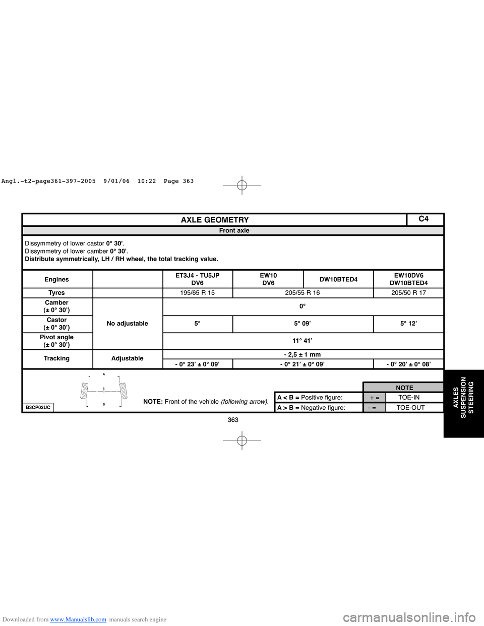
A < B = Positive figure: + = TOE-IN
A > B = Negative figure: - = TOE-OUTNOTE
AXLE GEOMETRY
Front axle
Dissymmetry of lower castor 0° 30'.
Dissymmetry of lower camber 0° 30'.
Distribute symmetrically, LH / RH wheel, the total tracking value.
EnginesET3J4 - TU5JP EW10
DW10BTED4EW10DV6
DV6 DV6 DW10BTED4
Tyres195/65 R 15 205/55 R 16 205/50 R 17
Camber
(± 0° 30’)0°
Castor
(± 0° 30’)No adjustable 5° 5° 09’ 5° 12’
Pivot angle
(± 0° 30’)11° 41’
Tracking Adjustable- 2,5 ± 1 mm
- 0° 23’ ± 0° 09’ - 0° 21’ ± 0° 09’ - 0° 20’ ± 0° 08’
NOTE:Front of the vehicle (following arrow).B3CP02UC
Angl.-t2-page361-397-2005 9/01/06 10:22 Page 363
Page 370 of 462

Downloaded from www.Manualslib.com manuals search engine AXLES
SUSPENSION
STEERING
C4
A < B = Positive figure: + = TOE-IN
A > B = Negative figure: - = TOE-OUTNOTE
AXLE GEOMETRY
Rear axle
Dissymmetry of lower camber 0° 30'.
EnginesET3J4 - TU5JP EW10DV6 EW10DV6
DV6 DW10BTED4 DW10BTED4
Tyres195/65 R 15 205/55 R 16 205/50 R 17
Camber
(± 0° 30’)No adjustable 1° 45’
Push angle
(± 0° 06’)0°
Tracking Adjustable6,5 ± 1 mm
0° 59’ ± 0° 09’ 0° 55’ ± 0° 09’ 0° 52’ ± 0° 08’
NOTE: Front of the vehicle (following arrow).B3CP02UC
364
Angl.-t2-page361-397-2005 9/01/06 10:22 Page 364