lamp Citroen XSARA PICASSO 2005 1.G Workshop Manual
[x] Cancel search | Manufacturer: CITROEN, Model Year: 2005, Model line: XSARA PICASSO, Model: Citroen XSARA PICASSO 2005 1.GPages: 462, PDF Size: 10.48 MB
Page 270 of 462
![Citroen XSARA PICASSO 2005 1.G Workshop Manual Downloaded from www.Manualslib.com manuals search engine 264
ENGINECHECKING AND SETTING THE VALVE TIMING
Tools.
[1]Belt tension measuring equipment : 4122-T
[2]Tension lever: (-).0188.J2
[3]Engine fly Citroen XSARA PICASSO 2005 1.G Workshop Manual Downloaded from www.Manualslib.com manuals search engine 264
ENGINECHECKING AND SETTING THE VALVE TIMING
Tools.
[1]Belt tension measuring equipment : 4122-T
[2]Tension lever: (-).0188.J2
[3]Engine fly](/img/9/4138/w960_4138-269.png)
Downloaded from www.Manualslib.com manuals search engine 264
ENGINECHECKING AND SETTING THE VALVE TIMING
Tools.
[1]Belt tension measuring equipment : 4122-T
[2]Tension lever: (-).0188.J2
[3]Engine flywheel peg: (-).0188.Y
[4] Belt clamp: (-).0188.AD
[5]Camshaft pulley peg: (-).0188.M
[6] Engine flywheel lock: (-).0188.F
[7] Set of blocking plugs: (-).0188.T
[8] Pulley extractor: (-).0188.P
[9] 2 mm Øpeg: (-).0188.Q2Removing.
IMPERATIVE: Respect the safety and cleanliness requirements
that are specific to high pressure diesel injection (HDi) engines.
Undo the front RH wheel bolts.
Raise and support the vehicle on the front RH side.
Disconnect the battery negative terminal.
Remove:
- The under-engine sound-deadening.
- The front RH wheel.
- The front RH splash-shield.
- The engine cover.
Unclip and move aside the cooling hose.
Remove the accessories drive belt
(see corresponding operation).
XSARA - XSARA PICASSO
Engines: RHY - RHZ
Angl.-t2-page240-282-2005 9/01/06 10:16 Page 264
Page 279 of 462
![Citroen XSARA PICASSO 2005 1.G Workshop Manual Downloaded from www.Manualslib.com manuals search engine 273
ENGINE
CHECKING AND SETTING THE VALVE TIMING
Engine: RHR
Tools.
[1]Kit of plugs: (-).0188.T
[2]Double flywheel setting peg: (-).0188.X
[3]C Citroen XSARA PICASSO 2005 1.G Workshop Manual Downloaded from www.Manualslib.com manuals search engine 273
ENGINE
CHECKING AND SETTING THE VALVE TIMING
Engine: RHR
Tools.
[1]Kit of plugs: (-).0188.T
[2]Double flywheel setting peg: (-).0188.X
[3]C](/img/9/4138/w960_4138-278.png)
Downloaded from www.Manualslib.com manuals search engine 273
ENGINE
CHECKING AND SETTING THE VALVE TIMING
Engine: RHR
Tools.
[1]Kit of plugs: (-).0188.T
[2]Double flywheel setting peg: (-).0188.X
[3]Camshaft setting peg: (-).0188.M
[4]Belt clamp: (-).0188.AD
[5]Pinion centrer: (-).0188.AH
[6]Flywheel lock: (-).0188.F
[7]Pulley(-).0188.P
IMPERATIVE: Respect the safety and cleanliness requirements specific to High pressure Diesel injection (HDi) engine versions.
Removing.
Slacken the front RH wheel bolts.
Raise and support the front RH side of the vehicle.
Disconnect the negative terminal of the battery.
Remove:
- The under-engine sound-deadening.
- The front RH wheel.
- The front RH splash-shield.
- The engine cover.
Remove the auxiliaries drive belt
(see corresponding operation).
C4
Angl.-t2-page240-282-2005 9/01/06 10:16 Page 273
Page 388 of 462
Downloaded from www.Manualslib.com manuals search engine 382
AXLES
SUSPENSION
STEERING
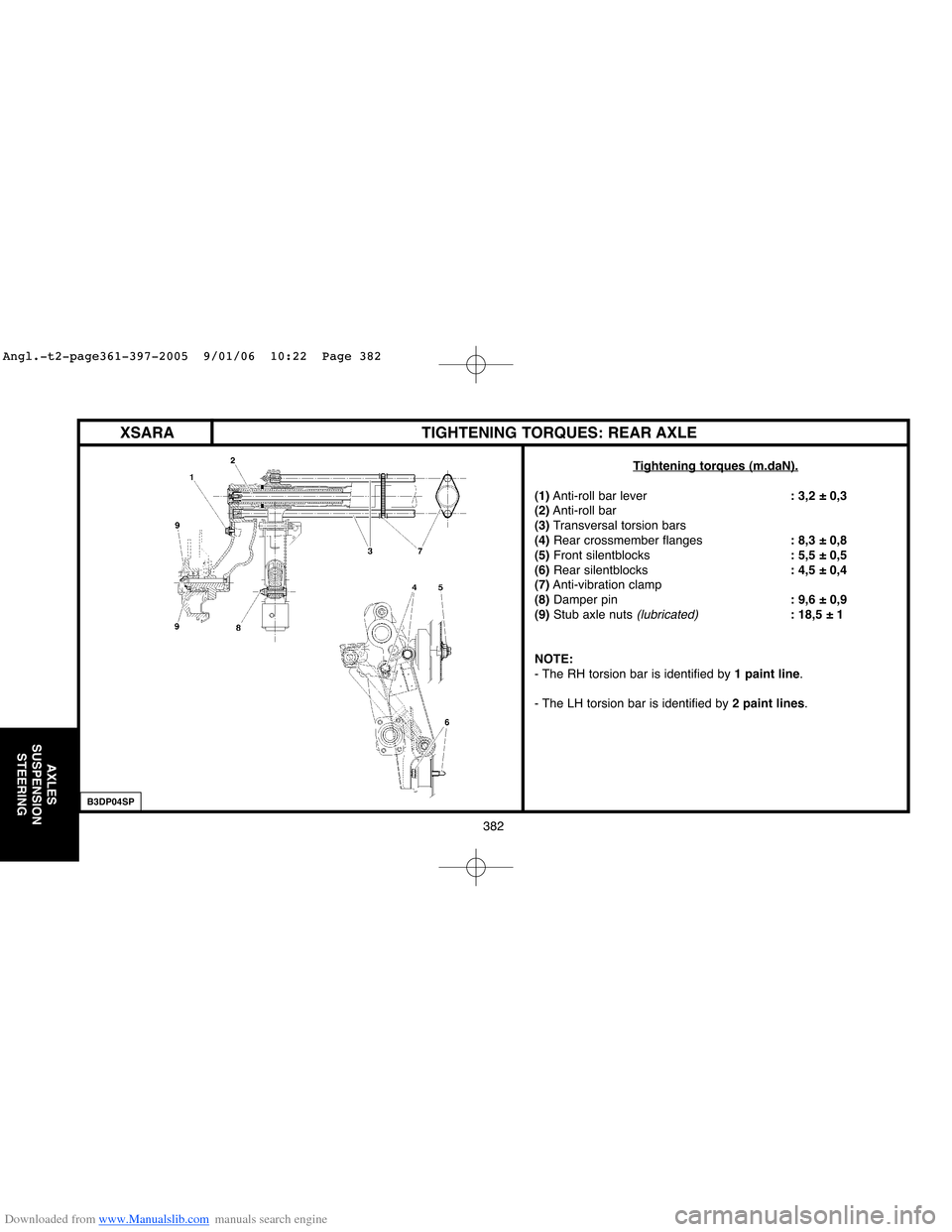
XSARA TIGHTENING TORQUES: REAR AXLE
Tightening torques (m.daN).
(1)Anti-roll bar lever: 3,2 ± 0,3
(2)Anti-roll bar
(3)Transversal torsion bars
(4)Rear crossmember flanges: 8,3 ± 0,8
(5)Front silentblocks: 5,5 ± 0,5
(6) Rear silentblocks: 4,5 ± 0,4
(7)Anti-vibration clamp
(8)Damper pin: 9,6 ± 0,9
(9)Stub axle nuts
(lubricated): 18,5 ± 1
NOTE:
- The RH torsion bar is identified by 1 paint line.
- The LH torsion bar is identified by 2 paint lines.
B3DP04SP
Angl.-t2-page361-397-2005 9/01/06 10:22 Page 382
Page 404 of 462
Downloaded from www.Manualslib.com manuals search engine 398
BRAKES
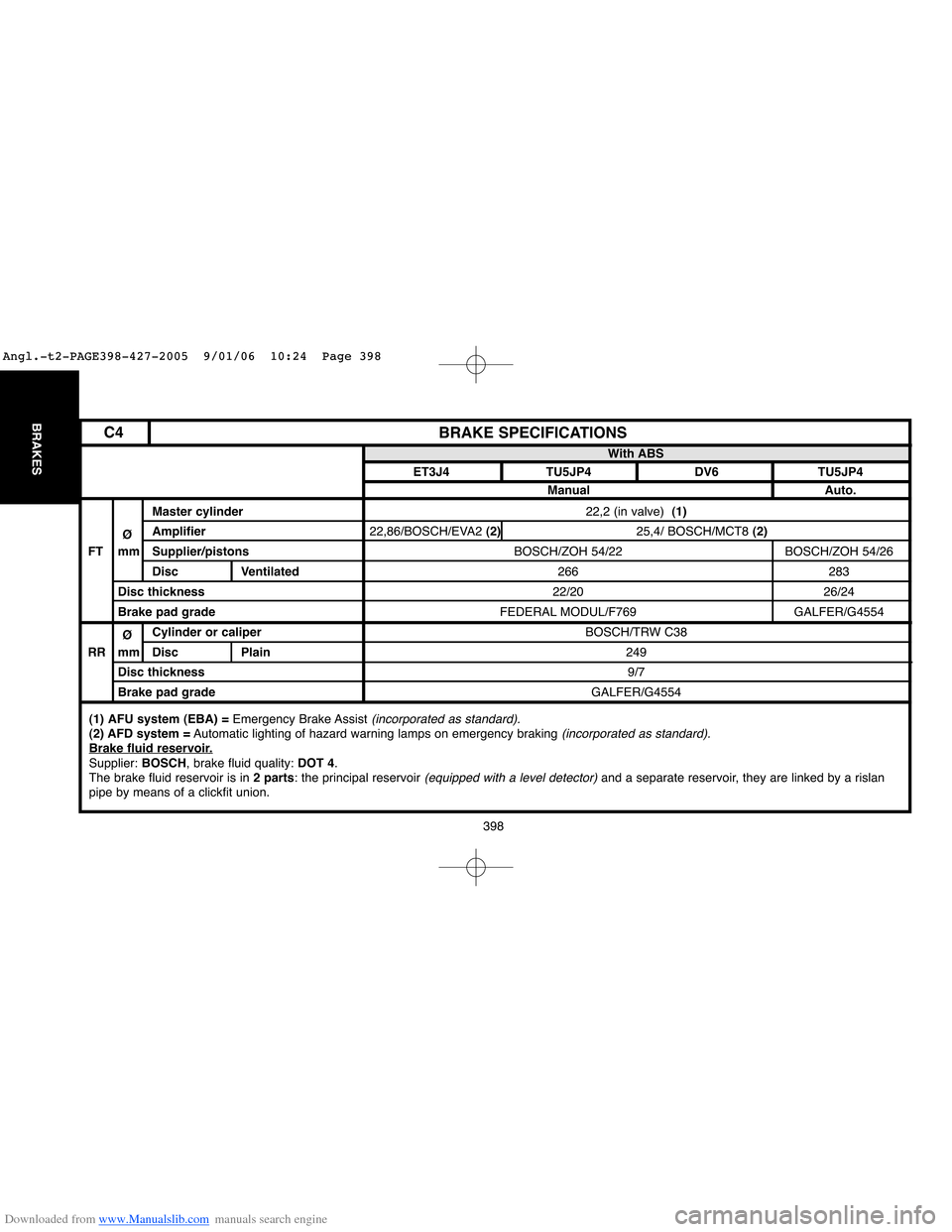
22,2 (in valve) (1)
22,86/BOSCH/EVA2 (2)25,4/ BOSCH/MCT8 (2)
BOSCH/ZOH 54/22 BOSCH/ZOH 54/26
266 283
22/20 26/24
FEDERAL MODUL/F769 GALFER/G4554
BOSCH/TRW C38
249
9/7
GALFER/G4554
BRAKE SPECIFICATIONS
Master cylinder
ØAmplifier
FT mm Supplier/pistons
Disc Ventilated
Disc thickness
Brake pad grade
ØCylinder or caliper
RR mm Disc Plain
Disc thickness
Brake pad gradeWith ABS
ET3J4 TU5JP4 DV6 TU5JP4
Manual Auto.
(1) AFU system (EBA) =Emergency Brake Assist (incorporated as standard).(2) AFD system =Automatic lighting of hazard warning lamps on emergency braking (incorporated as standard).Brake fluid reservoir.Supplier: BOSCH, brake fluid quality: DOT 4.
The brake fluid reservoir is in 2 parts: the principal reservoir (equipped with a level detector)and a separate reservoir, they are linked by a rislan
pipe by means of a clickfit union.
C4
Angl.-t2-PAGE398-427-2005 9/01/06 10:24 Page 398
Page 405 of 462
Downloaded from www.Manualslib.com manuals search engine 399
BRAKES
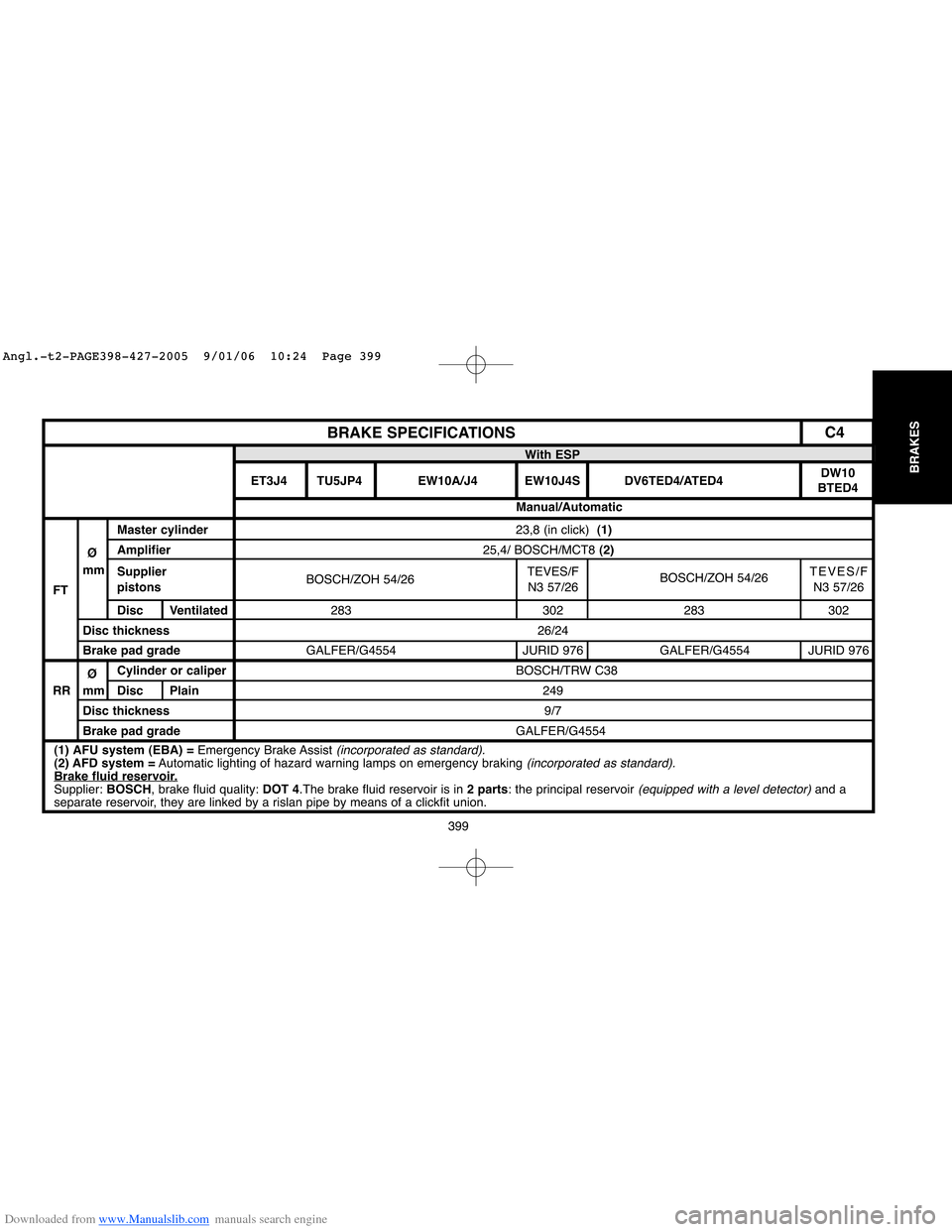
23,8 (in click) (1)
25,4/ BOSCH/MCT8 (2)
BOSCH/ZOH 54/26TEVES/F
BOSCH/ZOH 54/26TEVES/F
N3 57/26 N3 57/26
283 302 283 302
26/24
GALFER/G4554 JURID 976 GALFER/G4554 JURID 976
BOSCH/TRW C38
249
9/7
GALFER/G4554
BRAKE SPECIFICATIONS
Master cylinder
ØAmplifier
mm
Supplier
FTpistons
Disc Ventilated
Disc thickness
Brake pad grade
ØCylinder or caliper
RR mm Disc Plain
Disc thickness
Brake pad gradeWith ESP
ET3J4 TU5JP4 EW10A/J4 EW10J4S DV6TED4/ATED4DW10
BTED4
Manual/Automatic
(1) AFU system (EBA) =Emergency Brake Assist (incorporated as standard).(2) AFD system =Automatic lighting of hazard warning lamps on emergency braking (incorporated as standard).Brake fluid reservoir.Supplier: BOSCH, brake fluid quality: DOT 4.The brake fluid reservoir is in 2 parts: the principal reservoir (equipped with a level detector)and a
separate reservoir, they are linked by a rislan pipe by means of a clickfit union.
C4
Angl.-t2-PAGE398-427-2005 9/01/06 10:24 Page 399
Page 406 of 462
Downloaded from www.Manualslib.com manuals search engine B3FP7E1D
BRAKE SPECIFICATIONS
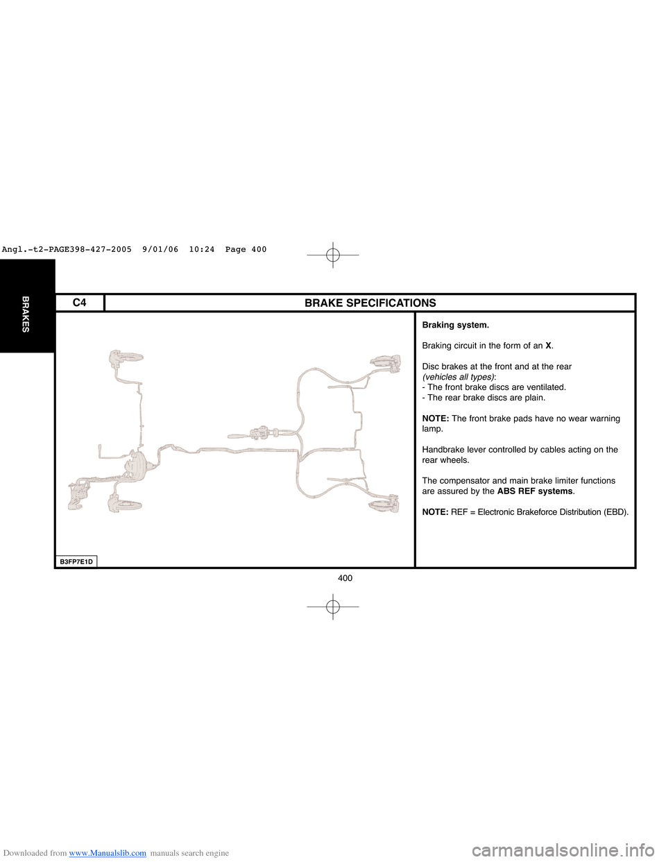
Braking system.
Braking circuit in the form of an X.
Disc brakes at the front and at the rear
(vehicles all types):
- The front brake discs are ventilated.
- The rear brake discs are plain.
NOTE: The front brake pads have no wear warning
lamp.
Handbrake lever controlled by cables acting on the
rear wheels.
The compensator and main brake limiter functions
are assured by the ABS REF systems.
NOTE:REF = Electronic Brakeforce Distribution (EBD).
400
BRAKESC4
Angl.-t2-PAGE398-427-2005 9/01/06 10:24 Page 400
Page 433 of 462
Downloaded from www.Manualslib.com manuals search engine 427
BRAKES
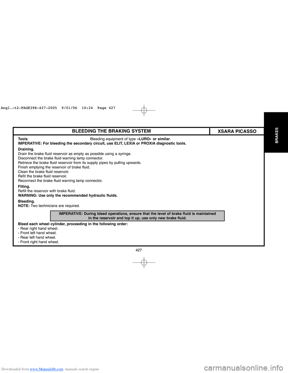
BLEEDING THE BRAKING SYSTEMXSARA PICASSO
Tools Bleeding equipment of type «LURO» or similar.
IMPERATIVE: For bleeding the secondary circuit, use ELIT, LEXIA or PROXIA diagnostic tools.
Draining.
Drain the brake fluid reservoir as empty as possible using a syringe.
Disconnect the brake fluid warning lamp connector.
Retrieve the brake fluid reservoir from its supply pipes by pulling upwards.
Finish emptying the reservoir of brake fluid.
Clean the brake fluid reservoir.
Refit the brake fluid reservoir.
Reconnect the brake fluid warning lamp connector.
Filling.
Refill the reservoir with brake fluid.
WARNING: Use only the recommended hydraulic fluids.
Bleeding.
NOTE:Two technicians are required.
IMPERATIVE: During bleed operations, ensure that the level of brake fluid is maintained
in the reservoir and top it up, use only new brake fluid.
Bleed each wheel cylinder, proceeding in the following order:
- Rear right hand wheel.
- Front left hand wheel.
- Rear left hand wheel.
- Front right hand wheel.
Angl.-t2-PAGE398-427-2005 9/01/06 10:24 Page 427