DAEWOO LACETTI 2004 Service Repair Manual
LACETTI 2004
DAEWOO
DAEWOO
https://www.carmanualsonline.info/img/54/56877/w960_56877-0.png
DAEWOO LACETTI 2004 Service Repair Manual
Trending: checking oil, seat, Ect, p0420, speedometer, engine controls, jump start terminals
Page 1571 of 2643
5A1 – 222IZF 4 HP 16 AUTOMATIC TRANSAXLE
DAEWOO V–121 BL4
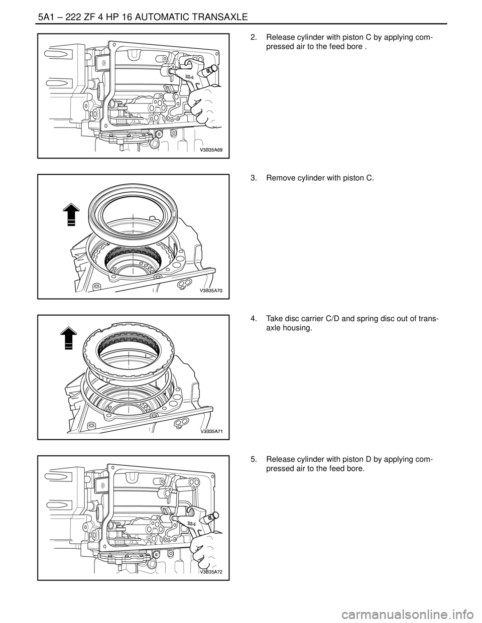
2. Release cylinder with piston C by applying com-
pressed air to the feed bore .
3. Remove cylinder with piston C.
4. Take disc carrier C/D and spring disc out of trans-
axle housing.
5. Release cylinder with piston D by applying com-
pressed air to the feed bore.
Page 1572 of 2643
ZF 4 HP 16 AUTOMATIC TRANSAXLE 5A1 – 223
DAEWOO V–121 BL4
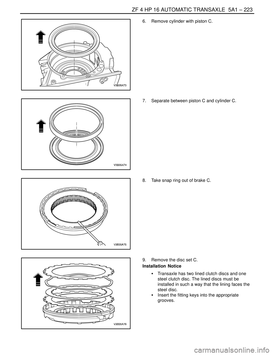
6. Remove cylinder with piston C.
7. Separate between piston C and cylinder C.
8. Take snap ring out of brake C.
9. Remove the disc set C.
Installation Notice
S Transaxle has two lined clutch discs and one
steel clutch disc. The lined discs must be
installed in such a way that the lining faces the
steel disc.
S Insert the fitting keys into the appropriate
grooves.
Page 1573 of 2643
5A1 – 224IZF 4 HP 16 AUTOMATIC TRANSAXLE
DAEWOO V–121 BL4
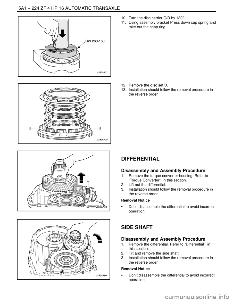
10. Turn the disc carrier C/D by 180°.
11. Using assembly bracket Press down cup spring and
take out the snap ring.
12. Remove the disc set D.
13. Installation should follow the removal procedure in
the reverse order.
DIFFERENTIAL
Disassembly and Assembly Procedure
1. Remove the torque converter housing. Refer to
”Torque Converter” in this section.
2. Lift out the differential.
3. Installation should follow the removal procedure in
the reverse order.
Removal Notice
S Don’t disassemble the differential to avoid incorrect
operation.
SIDE SHAFT
Disassembly and Assembly Procedure
1. Remove the differential. Refer to ”Differential” in
this section.
2. Tilt and remove the side shaft.
3. Installation should follow the removal procedure in
the reverse order.
Removal Notice
S Don’t disassemble the differential to avoid incorrect
operation.
Page 1574 of 2643
ZF 4 HP 16 AUTOMATIC TRANSAXLE 5A1 – 225
DAEWOO V–121 BL4
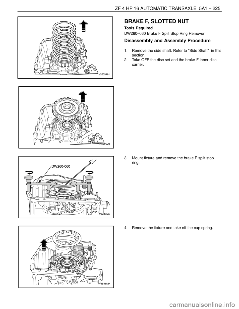
BRAKE F, SLOTTED NUT
Tools Required
DW260–060 Brake F Split Stop Ring Remover
Disassembly and Assembly Procedure
1. Remove the side shaft. Refer to ”Side Shaft” in this
section.
2. Take OFF the disc set and the brake F inner disc
carrier.
3. Mount fixture and remove the brake F split stop
ring.
4. Remove the fixture and take off the cup spring.
Page 1575 of 2643
5A1 – 226IZF 4 HP 16 AUTOMATIC TRANSAXLE
DAEWOO V–121 BL4
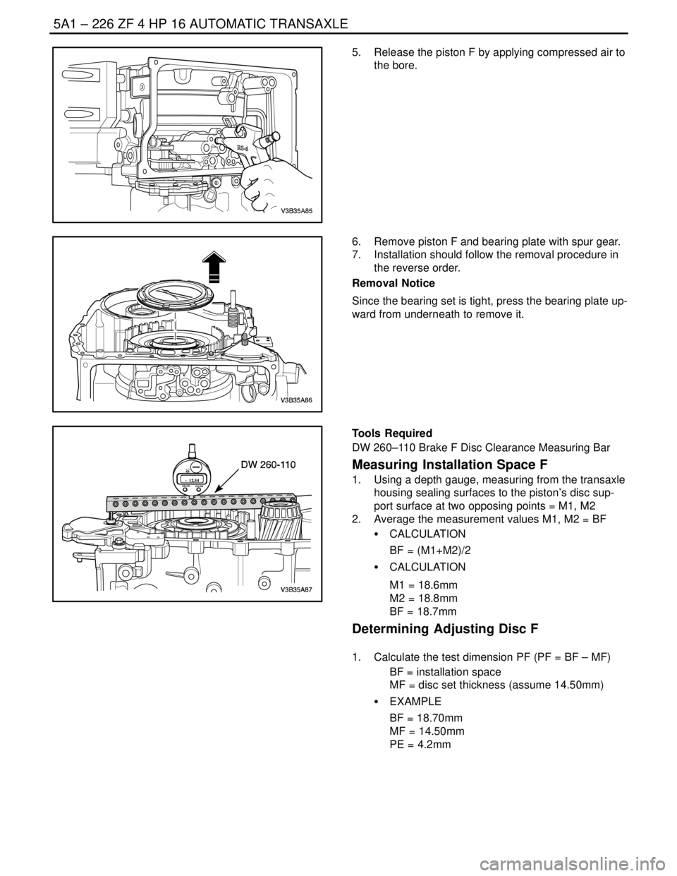
5. Release the piston F by applying compressed air to
the bore.
6. Remove piston F and bearing plate with spur gear.
7. Installation should follow the removal procedure in
the reverse order.
Removal Notice
Since the bearing set is tight, press the bearing plate up-
ward from underneath to remove it.
ORIGIN
ON/OFF– 12.54
+ / –
ORIGIN
ON/OFF– 12.54
+ / –
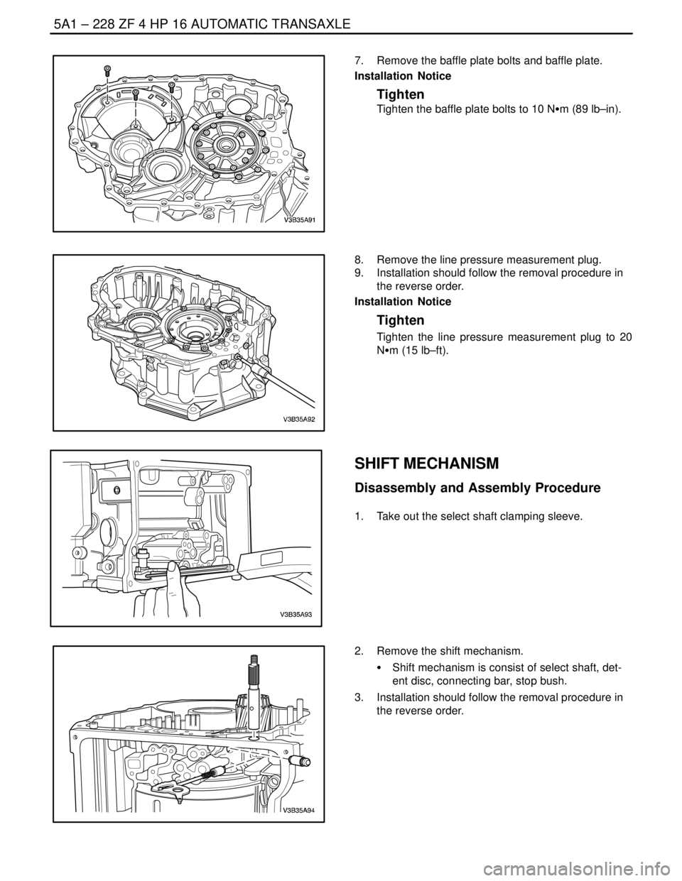
Tools Required
DW 260–110 Brake F Disc Clearance Measuring Bar
Measuring Installation Space F
1. Using a depth gauge, measuring from the transaxle
housing sealing surfaces to the piston’s disc sup-
port surface at two opposing points = M1, M2
2. Average the measurement values M1, M2 = BF
S CALCULATION
BF = (M1+M2)/2
S CALCULATION
M1 = 18.6mm
M2 = 18.8mm
BF = 18.7mm
Determining Adjusting Disc F
1. Calculate the test dimension PF (PF = BF – MF)
BF = installation space
MF = disc set thickness (assume 14.50mm)
S EXAMPLE
BF = 18.70mm
MF = 14.50mm
PE = 4.2mm
Page 1576 of 2643
ZF 4 HP 16 AUTOMATIC TRANSAXLE 5A1 – 227
DAEWOO V–121 BL4
2. Find the disc set’s thickness. Refer to the below
table.
PF
Disc set’s Thickness
3.01~3.19mm1.8mm
3.20~3.48mm2.1mm
3.49~3.88mm2.5mm
3.89~4.08mm2.7mm
4.09~4.30mm3.0mm
PE is 4.20mm so, the disc set’s thickness is
3.0mm.
3. Replace clutch B’s setting disc. (3.0mm)
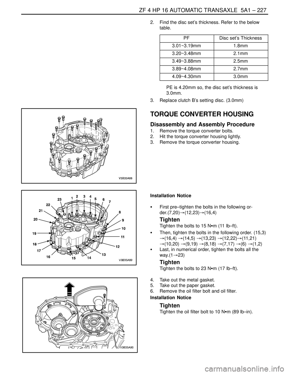
TORQUE CONVERTER HOUSING
Disassembly and Assembly Procedure
1. Remove the torque converter bolts.
2. Hit the torque converter housing lightly.
3. Remove the torque converter housing.
Installation Notice
S First pre–tighten the bolts in the following or-
der.(7,20)�(12,23)�(16,4)
Tighten
Tighten the bolts to 15 NSm (11 lb–ft).
S Then, tighten the bolts in the following order. (15,3)
�(16,4) �(14,5) �(13,23) �(12,22)�(11,21)
�(10,20) �(9,19) �(8,18) �(7,17) �(6) �(1,2)
S Last, in numerical order, tighten the bolts all the
way.(1�23)
Tighten
Tighten the bolts to 23 NSm (17 lb–ft).
4. Take out the metal gasket.
5. Take out the paper gasket.
6. Remove the oil filter bolt and oil filter.
Installation Notice
Tighten
Tighten the oil filter bolt to 10 NSm (89 lb–in).
Page 1577 of 2643
5A1 – 228IZF 4 HP 16 AUTOMATIC TRANSAXLE
DAEWOO V–121 BL4
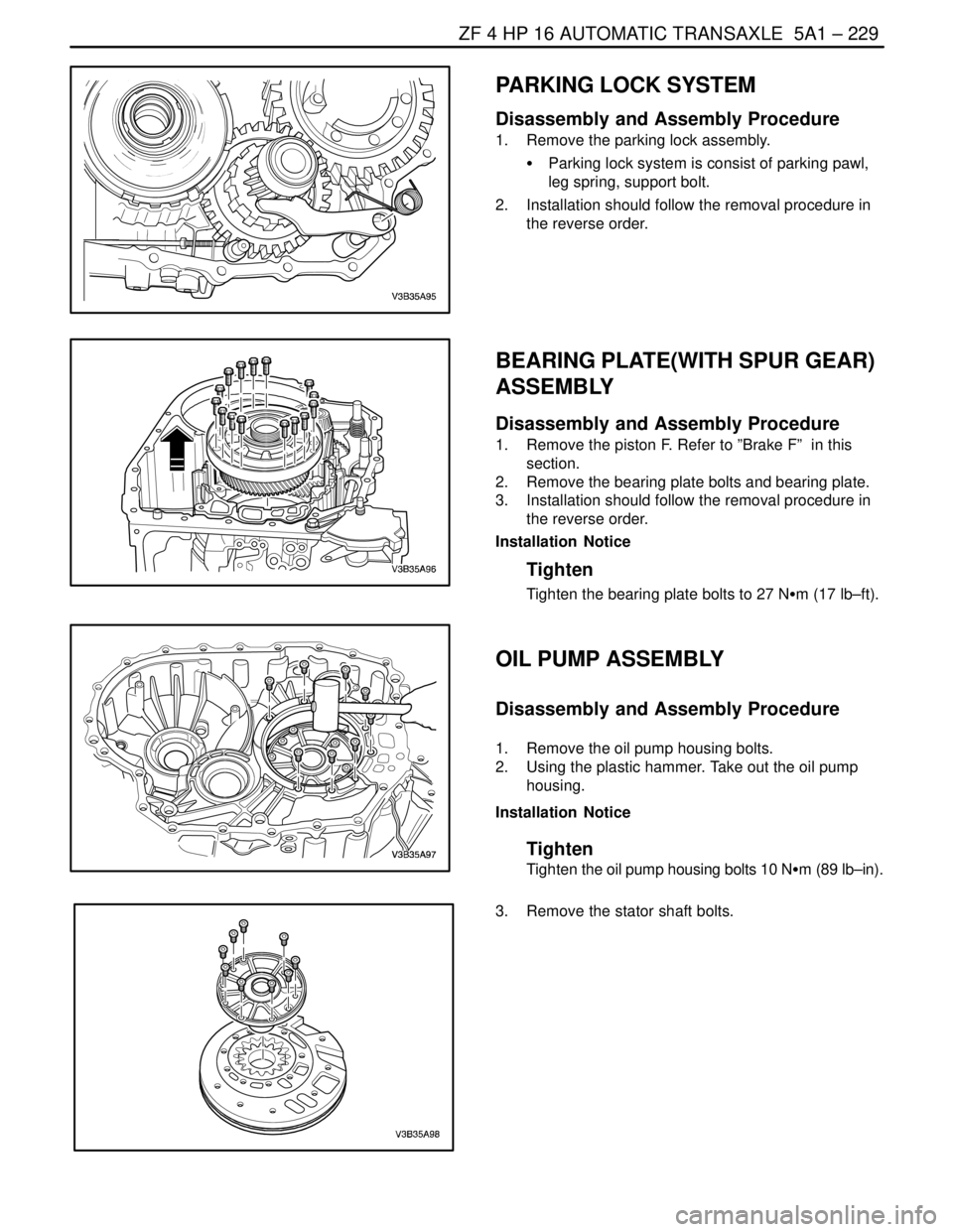
7. Remove the baffle plate bolts and baffle plate.
Installation Notice
Tighten
Tighten the baffle plate bolts to 10 NSm (89 lb–in).
8. Remove the line pressure measurement plug.
9. Installation should follow the removal procedure in
the reverse order.
Installation Notice
Tighten
Tighten the line pressure measurement plug to 20
NSm (15 lb–ft).
SHIFT MECHANISM
Disassembly and Assembly Procedure
1. Take out the select shaft clamping sleeve.
2. Remove the shift mechanism.
S Shift mechanism is consist of select shaft, det-
ent disc, connecting bar, stop bush.
3. Installation should follow the removal procedure in
the reverse order.
Page 1578 of 2643
ZF 4 HP 16 AUTOMATIC TRANSAXLE 5A1 – 229
DAEWOO V–121 BL4
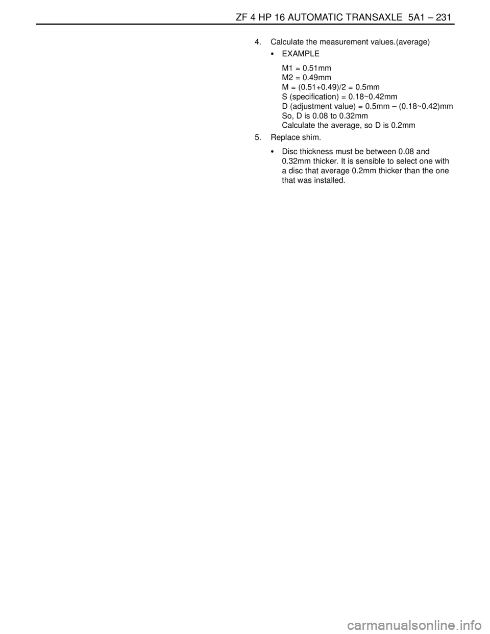
PARKING LOCK SYSTEM
Disassembly and Assembly Procedure
1. Remove the parking lock assembly.
S Parking lock system is consist of parking pawl,
leg spring, support bolt.
2. Installation should follow the removal procedure in
the reverse order.
BEARING PLATE(WITH SPUR GEAR)
ASSEMBLY
Disassembly and Assembly Procedure
1. Remove the piston F. Refer to ”Brake F” in this
section.
2. Remove the bearing plate bolts and bearing plate.
3. Installation should follow the removal procedure in
the reverse order.
Installation Notice
Tighten
Tighten the bearing plate bolts to 27 NSm (17 lb–ft).
OIL PUMP ASSEMBLY
Disassembly and Assembly Procedure
1. Remove the oil pump housing bolts.
2. Using the plastic hammer. Take out the oil pump
housing.
Installation Notice
Tighten
Tighten the oil pump housing bolts 10 NSm (89 lb–in).
3. Remove the stator shaft bolts.
Page 1579 of 2643
5A1 – 230IZF 4 HP 16 AUTOMATIC TRANSAXLE
DAEWOO V–121 BL4
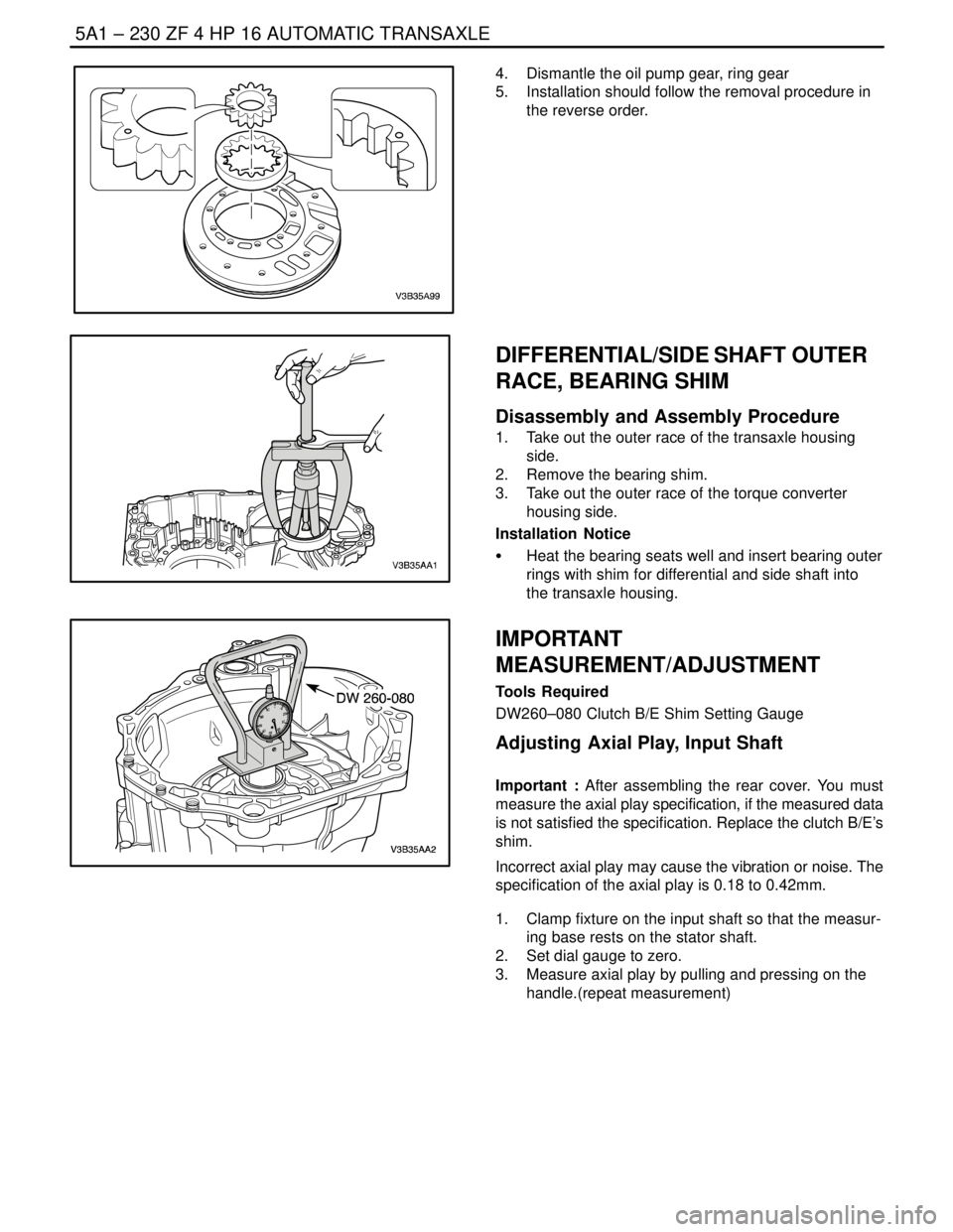
4. Dismantle the oil pump gear, ring gear
5. Installation should follow the removal procedure in
the reverse order.
DIFFERENTIAL/SIDE SHAFT OUTER
RACE, BEARING SHIM
Disassembly and Assembly Procedure
1. Take out the outer race of the transaxle housing
side.
2. Remove the bearing shim.
3. Take out the outer race of the torque converter
housing side.
Installation Notice
S Heat the bearing seats well and insert bearing outer
rings with shim for differential and side shaft into
the transaxle housing.
IMPORTANT
MEASUREMENT/ADJUSTMENT
Tools Required
DW260–080 Clutch B/E Shim Setting Gauge
Adjusting Axial Play, Input Shaft
Important : After assembling the rear cover. You must
measure the axial play specification, if the measured data
is not satisfied the specification. Replace the clutch B/E’s
shim.
Incorrect axial play may cause the vibration or noise. The
specification of the axial play is 0.18 to 0.42mm.
1. Clamp fixture on the input shaft so that the measur-
ing base rests on the stator shaft.
2. Set dial gauge to zero.
3. Measure axial play by pulling and pressing on the
handle.(repeat measurement)
Page 1580 of 2643
ZF 4 HP 16 AUTOMATIC TRANSAXLE 5A1 – 231
DAEWOO V–121 BL4
4. Calculate the measurement values.(average)
S EXAMPLE
M1 = 0.51mm
M2 = 0.49mm
M = (0.51+0.49)/2 = 0.5mm
S (specification) = 0.18~0.42mm
D (adjustment value) = 0.5mm – (0.18~0.42)mm
So, D is 0.08 to 0.32mm
Calculate the average, so D is 0.2mm
5. Replace shim.
S Disc thickness must be between 0.08 and
0.32mm thicker. It is sensible to select one with
a disc that average 0.2mm thicker than the one
that was installed.
Trending: AUX, hood release cable, hood cable, coolant reservoir, spark plugs replace, spark, ACC
