Front suspension DAEWOO LACETTI 2004 Service User Guide
[x] Cancel search | Manufacturer: DAEWOO, Model Year: 2004, Model line: LACETTI, Model: DAEWOO LACETTI 2004Pages: 2643, PDF Size: 80.54 MB
Page 917 of 2643

2B – 10IWHEEL ALIGNMENT
DAEWOO V–121 BL4
GENERAL DESCRIPTION
AND SYSTEM OPERATION
FOUR WHEEL ALIGNMENT
The first responsibility of engineering is to design safe
steering and suspension systems. Each component must
be strong enough to withstand and absorb extreme pun-
ishment. Both the steering system and the front and the
rear suspension must function geometrically with the body
mass.
The steering and the suspension systems require that the
front wheels self–return and that the tire rolling effort and
the road friction be held to a negligible force in order to al-
low the customer to direct the vehicle with the least effort
and the most comfort.
A complete wheel alignment check should include mea-
surements of the rear toe and camber.
Four–wheel alignment assures that all four wheels will be
running in precisely the same direction.
When the vehicle is geometrically aligned, fuel economy
and tire life are at their peak, and steering and perfor-
mance are maximized.
TOE
Toe–in is the turning in of the tires, while toe–out is the
turning out of the tires from the geometric centerline or
thrust line. The toe ensures parallel rolling of the wheels.
The toe serves to offset the small deflections of the wheel
support system which occur when the vehicle is rolling for-
ward. The specified toe angle is the setting which achieves
0 degrees of toe when the vehicle is moving.
Incorrect toe–in or toe–out will cause tire wear and re-
duced fuel economy. As the individual steering and sus-
pension components wear from vehicle mileage, addition-
al toe will be needed to compensate for the wear.
Always correct the toe dimension last.
CASTER
Caster is the tilting of the uppermost point of the steering
axis either forward or backward from the vertical when
viewed from the side of the vehicle. A backward tilt is posi-
tive, and a forward tilt is negative. Caster influences direc-
tional control of the steering but does not affect tire wear.
Weak springs or overloading a vehicle will affect caster.
One wheel with more positive caster will pull toward the
center of the car. This condition will cause the car to move
or lean toward the side with the least amount of positive
caster. Caster is measured in degrees and is not adjust-
able.
CAMBER
Camber is the tilting of the top of the tire from the vertical
when viewed from the front of the vehicle. When the tires
tilt outward, the camber is positive. When the tires tilt in-
ward, the camber is negative. The camber angle is mea-
sured in degrees from the vertical. Camber influences
both directional control and tire wear.
If the vehicle has too much positive camber, the outside
shoulder of the tire will wear. If the vehicle has too much
negative camber, the inside shoulder of the tire will wear.
Camber is not adjustable.
STEERING AXIS INCLINATION
Steering Axis Inclination (SAI) is the tilt at the top of the
steering knuckle from the vertical. Measure the SAI angle
from the true vertical to a line through the center of the strut
and the lower ball joint as viewed from the front of the ve-
hicle.
SAI helps the vehicle track straight down the road and as-
sists the wheel back into the straight ahead position. SAI
on front wheel drive vehicles should be negative.
INCLUDED ANGLE
The included angle is the angle measured from the cam-
ber angle to the line through the center of the strut and the
lower ball joint as viewed from the front of the vehicle.
The included angle is calculated in degrees. Most align-
ment racks will not measure the included angle directly. To
determine the included angle, subtract the negative or add
the positive camber readings to the Steering Axis Inclina-
tion (SAI).
SCRUB RADIUS
The scrub radius is the distance between true vertical and
the line through the center of the strut and lower ball joint
to the road surface. Scrub radius is built into the design of
the vehicle. Scrub radius is not adjustable.
SETBACK
The setback is the distance in which one front hub and
bearing assembly may be rearward of the other front hub
and bearing assembly. Setback is primarily caused by a
road hazard or vehicle collision.
TURNING ANGLE
The turning angle is the angle of each front wheel to the
vertical when the vehicle is making a turn.
Page 918 of 2643

SECTION : 2C
FRONT SUSPENSION
CAUTION : Disconnect the negative battery cable before removing or installing any electrical unit or when a tool
or equipment could easily come in contact with exposed electrical terminals. Disconnecting this cable will help
prevent personal injury and damage to the vehicle. The ignition must also be in LOCK unless otherwise noted.
TABLE OF CONTENTS
SPECIFICATIONS2C–2 . . . . . . . . . . . . . . . . . . . . . . . . . .
General Specifications 2C–2. . . . . . . . . . . . . . . . . . . . .
Fastener Tightening Specifications 2C–2. . . . . . . . . . .
SPECIAL TOOLS2C–3 . . . . . . . . . . . . . . . . . . . . . . . . . . .
Special Tools Table 2C–3. . . . . . . . . . . . . . . . . . . . . . . .
DIAGNOSIS2C–5 . . . . . . . . . . . . . . . . . . . . . . . . . . . . . . . .
Strut Dampener 2C–5. . . . . . . . . . . . . . . . . . . . . . . . . . .
Ball Joint and Knuckle 2C–6. . . . . . . . . . . . . . . . . . . . . .
Excessive Friction Check 2C–6. . . . . . . . . . . . . . . . . . .
COMPONENT LOCATOR2C–7 . . . . . . . . . . . . . . . . . . . .
Front Suspension 2C–7. . . . . . . . . . . . . . . . . . . . . . . . . .
MAINTENANCE AND REPAIR2C–9 . . . . . . . . . . . . . . .
ON–VEHICLE SERVICE 2C–9. . . . . . . . . . . . . . . . . . . . .
Stabilizer Shaft and Insulators 2C–9. . . . . . . . . . . . . . . Stabilizer Link 2C–10. . . . . . . . . . . . . . . . . . . . . . . . . . . .
Knuckle Assembly 2C–10. . . . . . . . . . . . . . . . . . . . . . . .
Hub and Bearing 2C–13. . . . . . . . . . . . . . . . . . . . . . . . .
Control Arm 2C–14. . . . . . . . . . . . . . . . . . . . . . . . . . . . . .
Strut Assembly 2C–16. . . . . . . . . . . . . . . . . . . . . . . . . . .
Crossmember Assembly 2C–18. . . . . . . . . . . . . . . . . . .
UNIT REPAIR 2C–21. . . . . . . . . . . . . . . . . . . . . . . . . . . . .
Ball Joint 2C–21. . . . . . . . . . . . . . . . . . . . . . . . . . . . . . . .
Control Arm Bushings 2C–21. . . . . . . . . . . . . . . . . . . . .
Front Strut Assembly 2C–22. . . . . . . . . . . . . . . . . . . . . .
Knuckle 2C–23. . . . . . . . . . . . . . . . . . . . . . . . . . . . . . . . .
GENERAL DESCRIPTION AND SYSTEM
OPERATION 2C–25 . . . . . . . . . . . . . . . . . . . . . . . . . . . .
Front Suspension 2C–25. . . . . . . . . . . . . . . . . . . . . . . . .
Page 919 of 2643

2C – 2IFRONT SUSPENSION
DAEWOO V–121 BL4
SPECIFICATIONS
GENERAL SPECIFICATIONS
ApplicationTrim Height
Center of Front Wheel to Bottom of Front Wheel Well368 mm (14.4 in.)
Center of Rear Wheel to Bottom of Rear Wheel Well367 mm (14.4 in.)
* CONDITION : Full Fuel in the Tank
FASTENER TIGHTENING SPECIFICATIONS
ApplicationNSmLb–FtLb–In
Ball Joint Pinch Bolt Nut6044–
Ball Joint–to–Control Arm Nuts10074–
Front Control Arm–to–Crossmember Bolt12592–
Rear Contral Arm–to–Crossmember Bolt11 081–
Crossmember Link–to–Crossmember Bolt11 484–
Crossmember Link–to–Transaxle Bracket Nut169125–
Drive Axle–to–Hub Caulking Nut300221–
Front Crossmember–to–Body Bolts13096–
Piston Rod Nut7555–
Rear Crossmember–to–Body Bolts196145–
Stabilizer Link–to–Strut Assembly Nut4735–
Stabilizer Shaft–to–Crossmember Clamp Bolts2518–
Stabilizer Shaft–to–Stabilizer Link Nut4735–
Steering Knuckle–to–Strut Assembly Nuts/Bolts12089–
Strut Assembly–to–Body Nut6548–
Page 920 of 2643
FRONT SUSPENSION 2C – 3
DAEWOO V–121 BL4
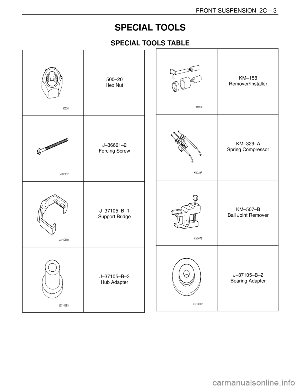
SPECIAL TOOLS
SPECIAL TOOLS TABLE
500–20
Hex Nut
J–36661–2
Forcing Screw
J–37105–B–1
Support Bridge
J–37105–B–3
Hub Adapter
KM–158
Remover/Installer
KM–329–A
Spring Compressor
KM–507–B
Ball Joint Remover
J–37105–B–2
Bearing Adapter
Page 921 of 2643

2C – 4IFRONT SUSPENSION
DAEWOO V–121 BL4
J–42468
Front Strut Mount
Nut Wrench
Page 922 of 2643

FRONT SUSPENSION 2C – 5
DAEWOO V–121 BL4
DIAGNOSIS
STRUT DAMPENER
A strut dampener is basically a shock absorber. However, strut dampeners are easier to extend and retract by hand than
are shock absorbers.
Struts Seem Weak
ChecksAction
Check the tire pressures.Adjust the tire pressures to the specifications on the tire
placard.
Check the load conditions under which the vehicle is nor-
mally driven.Consult with the owner to confirm the owner’s understand-
ing of normal load conditions.
Check the compression and rebound effectiveness of the
strut dampener.Quickly push down and then lift up on the corner of the
bumper nearest the strut dampener being tested.
Compare the compression and rebound with those of a
similar vehicle that has an acceptable ride quality.
Replace the strut dampener, if needed.
Struts Are Noisy
ChecksAction
Check the mountings for looseness or damage.Tighten the strut dampener mounting nuts. Replace the
strut dampener, if needed.
Check the compression and rebound effectiveness of the
strut dampener.Quickly push down and then lift up on the corner of the
bumper nearest the strut dampener being tested.
Compare the compression and rebound with those of a
similar vehicle that has an acceptable ride quality.
Replace the strut dampener, if needed.
Leaks
ChecksAction
Check for a slight trace of fluid.The strut dampener is OK.
Check the integrity of the seal cover on the fully extended
strut.Replace the strut dampener.
Check for an excessive amount of fluid on the strut damp-
ener.Replace the strut dampener.
Page 923 of 2643

2C – 6IFRONT SUSPENSION
DAEWOO V–121 BL4
BALL JOINT AND KNUCKLE
Ball Joint Inspection
1. Raise the front of the vehicle to allow the front sus-
pension to hang free.
2. Grasp the tire at the top and the bottom.
3. Move the top of the tire in an in–and–out motion.
4. Look for any horizontal movement of the knuckle
relative to the control arm.
5. Ball joints must be replaced under the following
conditions:
S The joint is loose.
S The ball seal is cut.
S The ball stud is disconnected from the knuckle.
S The ball stud is loose at the knuckle.
S The ball stud can be twisted in its socket with
finger pressure.
Ball Stud Inspection
Make sure to check the tightness of the ball stud in the
knuckle boss during each inspection of the ball joint. One
way to inspect the ball stud for wear is to shake the wheel
and feel for movement of the stud end at the knuckle boss.Another way to inspect the ball stud for wear is to check
the fastener torque at the pinch nut. A loose nut can indi-
cate a stressed stud or a hole in the knuckle boss.
Worn or damaged ball joints and knuckles must be re-
placed.
EXCESSIVE FRICTION CHECK
Use the following procedure to check for excessive friction
in the front suspension:
1. Enlist the help of another technician to lift up on the
front bumper, raising the vehicle as high as pos-
sible.
2. Slowly release the bumper, allowing the vehicle to
assume its normal trim height. See ”General Speci-
fications” in this section.
3. Measure the distance from the street level to the
center of the bumper.
4. Push down on the bumper, release slowly, and al-
low the vehicle to assume its normal trim height.
5. Measure the distance from the street level to the
center of the bumper.
6. The difference between the two measurements
should be less than 12.7 mm (0.5 inch). If the differ-
ence exceeds this limit, inspect the control arms,
the struts, and the ball joints for damage or wear.
Page 924 of 2643
FRONT SUSPENSION 2C – 7
DAEWOO V–121 BL4
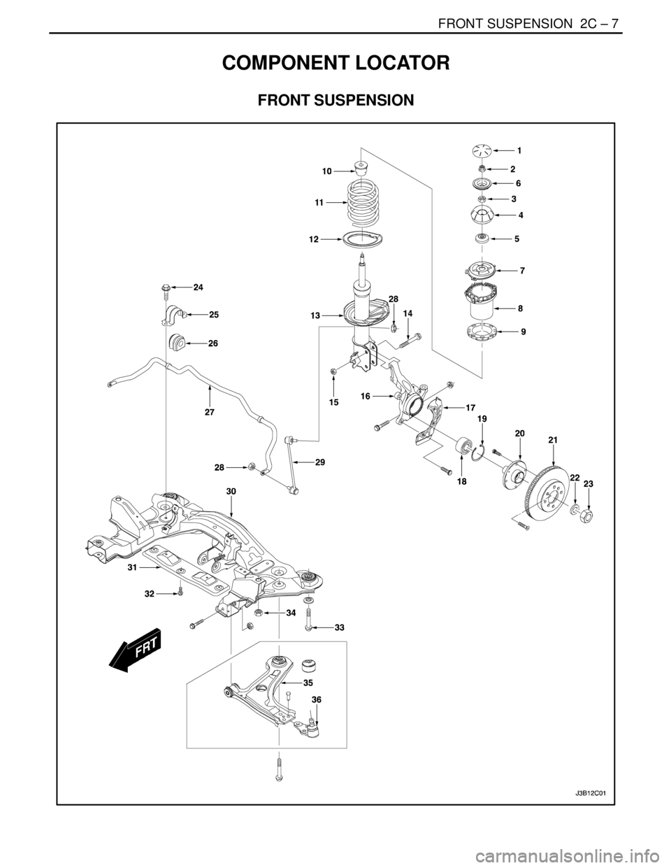
COMPONENT LOCATOR
FRONT SUSPENSION
Page 925 of 2643

2C – 8IFRONT SUSPENSION
DAEWOO V–121 BL4
1. Cap
2. Strut Upper Nut
3. Piston Rod Nut
4. Strut Mount
5. Strut Bearing
6. Washer
7. Upper Spring Seat
8. Front Spring Locator
9. Upper Spring Insulator
10. Hollow Bumper
11. Front Coil Spring
12. Lower Spring Insulator
13. Front Strut
14. Steering Knuckle–to–Strut Assembly
15. Nut
16. Steering Knuckle
17. Brake Shield
18. Front Hub Bearing19. Outer Snap Ring
20. Front Hub
21. Front Brake Disc
22. Washer
23. Caulking Nut
24. Stabilizer Clamp Bolt
25. Stabilizer Clamp
26. Stabilizer Clamp Insulator
27. Stabilizer
28. Stabilizer Link Nut
29. Stabilizer Link
30. Front Suspension Crossmember
31. Crossmember Cover
32. Crossmember Cover Bolt
33. Crossmember Bolt
34. Crossmember Nut
35. Control Arm
36. Ball Joint
Page 926 of 2643
FRONT SUSPENSION 2C – 9
DAEWOO V–121 BL4
MAINTENANCE AND REPAIR
ON–VEHICLE SERVICE
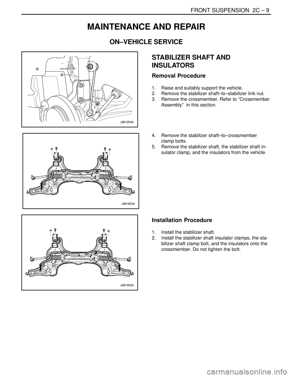
STABILIZER SHAFT AND
INSULATORS
Removal Procedure
1. Raise and suitably support the vehicle.
2. Remove the stabilizer shaft–to–stabilizer link nut.
3. Remove the crossmember. Refer to ”Crossmember
Assembly” in this section.
4. Remove the stabilizer shaft–to–crossmember
clamp bolts.
5. Remove the stabilizer shaft, the stabilizer shaft in-
sulator clamp, and the insulators from the vehicle.
Installation Procedure
1. Install the stabilizer shaft.
2. Install the stabilizer shaft insulator clamps, the sta-
bilizer shaft clamp bolt, and the insulators onto the
crossmember. Do not tighten the bolt.