brakes DAEWOO LACETTI 2004 Service User Guide
[x] Cancel search | Manufacturer: DAEWOO, Model Year: 2004, Model line: LACETTI, Model: DAEWOO LACETTI 2004Pages: 2643, PDF Size: 80.54 MB
Page 931 of 2643
2C – 14IFRONT SUSPENSION
DAEWOO V–121 BL4
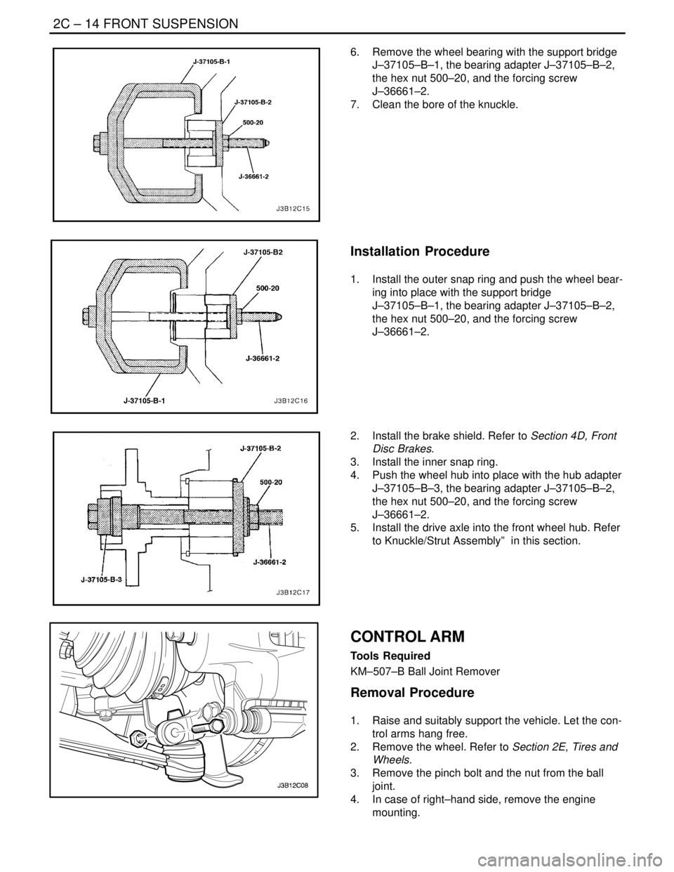
6. Remove the wheel bearing with the support bridge
J–37105–B–1, the bearing adapter J–37105–B–2,
the hex nut 500–20, and the forcing screw
J–36661–2.
7. Clean the bore of the knuckle.
Installation Procedure
1. Install the outer snap ring and push the wheel bear-
ing into place with the support bridge
J–37105–B–1, the bearing adapter J–37105–B–2,
the hex nut 500–20, and the forcing screw
J–36661–2.
2. Install the brake shield. Refer to Section 4D, Front
Disc Brakes.
3. Install the inner snap ring.
4. Push the wheel hub into place with the hub adapter
J–37105–B–3, the bearing adapter J–37105–B–2,
the hex nut 500–20, and the forcing screw
J–36661–2.
5. Install the drive axle into the front wheel hub. Refer
to Knuckle/Strut Assembly” in this section.
CONTROL ARM
Tools Required
KM–507–B Ball Joint Remover
Removal Procedure
1. Raise and suitably support the vehicle. Let the con-
trol arms hang free.
2. Remove the wheel. Refer to Section 2E, Tires and
Wheels.
3. Remove the pinch bolt and the nut from the ball
joint.
4. In case of right–hand side, remove the engine
mounting.
Page 940 of 2643
FRONT SUSPENSION 2C – 23
DAEWOO V–121 BL4
Important : Record the position of the front spring locator
relative to the strut assembly–to–knuckle bracket. Place
the front spring locator back in the same position during
assembly.
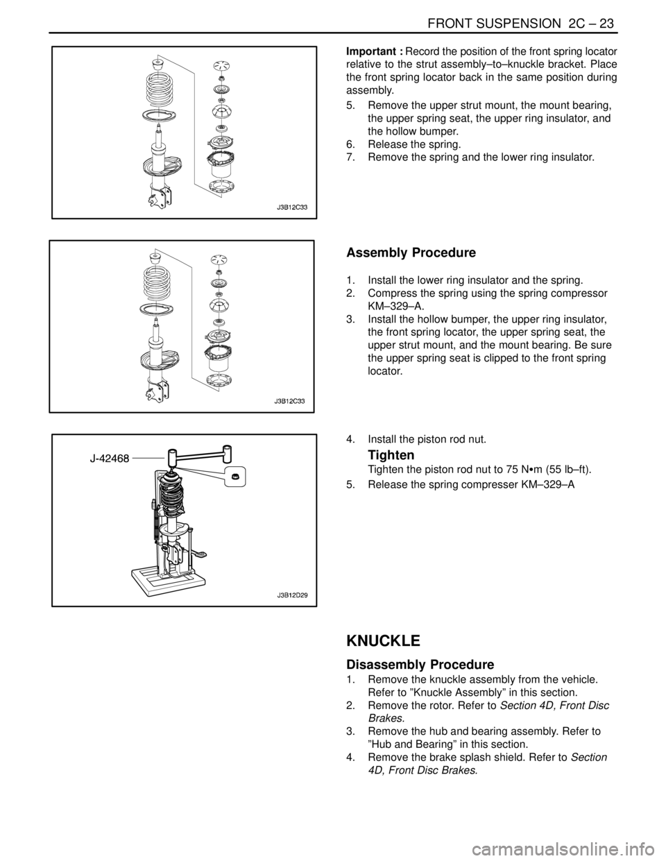
5. Remove the upper strut mount, the mount bearing,
the upper spring seat, the upper ring insulator, and
the hollow bumper.
6. Release the spring.
7. Remove the spring and the lower ring insulator.
Assembly Procedure
1. Install the lower ring insulator and the spring.
2. Compress the spring using the spring compressor
KM–329–A.
3. Install the hollow bumper, the upper ring insulator,
the front spring locator, the upper spring seat, the
upper strut mount, and the mount bearing. Be sure
the upper spring seat is clipped to the front spring
locator.
4. Install the piston rod nut.
Tighten
Tighten the piston rod nut to 75 NSm (55 lb–ft).
5. Release the spring compresser KM–329–A
KNUCKLE
Disassembly Procedure
1. Remove the knuckle assembly from the vehicle.
Refer to ”Knuckle Assembly” in this section.
2. Remove the rotor. Refer to Section 4D, Front Disc
Brakes.
3. Remove the hub and bearing assembly. Refer to
”Hub and Bearing” in this section.
4. Remove the brake splash shield. Refer to Section
4D, Front Disc Brakes.
Page 941 of 2643

2C – 24IFRONT SUSPENSION
DAEWOO V–121 BL4
Assembly Procedure
1. Install the brake splash shield. Refer to Section 4D,
Front Disc Brakes.
2. Install the hub and bearing assembly. Refer to ”Hub
and Bearing” in this section.
3. Install the rotor. Refer to Section 4D, Front Disc
Brakes.
4. Install the knuckle assembly onto the vehicle. Refer
to ”Knuckle Assembly” in this section.
Page 948 of 2643
2D – 6IREAR SUSPENSION
DAEWOO V–121 BL4
MAINTENANCE AND REPAIR
ON–VEHICLE SERVICE
STRUT ASSEMBLY
Removal Procedure
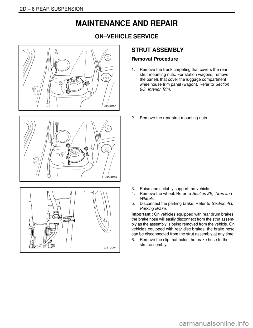
1. Remove the trunk carpeting that covers the rear
strut mounting nuts. For station wagons, remove
the panels that cover the luggage compartment
wheelhouse trim panel (wagon). Refer to Section
9G, Interior Trim.
2. Remove the rear strut mounting nuts.
3. Raise and suitably support the vehicle.
4. Remove the wheel. Refer to Section 2E, Tires and
Wheels.
5. Disconnect the parking brake. Refer to Section 4G,
Parking Brake.
Important : On vehicles equipped with rear drum brakes,
the brake hose will easily disconnect from the strut assem-
bly as the assembly is being removed from the vehicle. On
vehicles equipped with rear disc brakes, the brake hose
can be disconnected from the strut assembly at any time.
6. Remove the clip that holds the brake hose to the
strut assembly.
Page 949 of 2643
REAR SUSPENSION 2D – 7
DAEWOO V–121 BL4
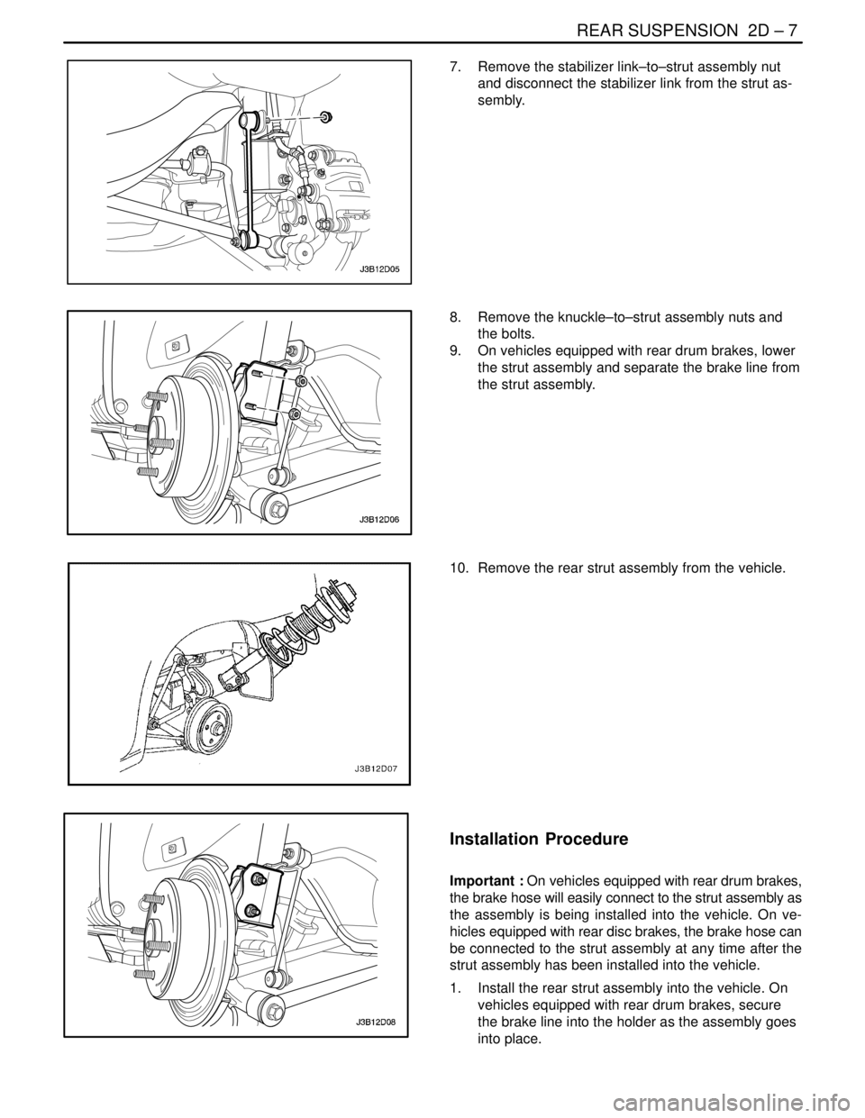
7. Remove the stabilizer link–to–strut assembly nut
and disconnect the stabilizer link from the strut as-
sembly.
8. Remove the knuckle–to–strut assembly nuts and
the bolts.
9. On vehicles equipped with rear drum brakes, lower
the strut assembly and separate the brake line from
the strut assembly.
10. Remove the rear strut assembly from the vehicle.
Installation Procedure
Important : On vehicles equipped with rear drum brakes,
the brake hose will easily connect to the strut assembly as
the assembly is being installed into the vehicle. On ve-
hicles equipped with rear disc brakes, the brake hose can
be connected to the strut assembly at any time after the
strut assembly has been installed into the vehicle.
1. Install the rear strut assembly into the vehicle. On
vehicles equipped with rear drum brakes, secure
the brake line into the holder as the assembly goes
into place.
Page 951 of 2643
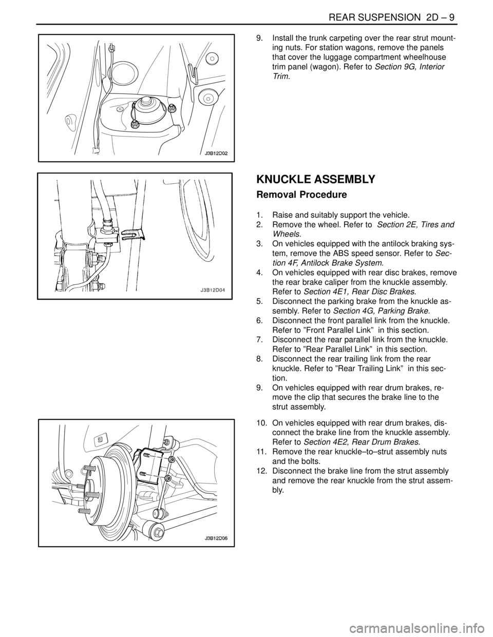
REAR SUSPENSION 2D – 9
DAEWOO V–121 BL4
9. Install the trunk carpeting over the rear strut mount-
ing nuts. For station wagons, remove the panels
that cover the luggage compartment wheelhouse
trim panel (wagon). Refer to Section 9G, Interior
Trim.
KNUCKLE ASSEMBLY
Removal Procedure
1. Raise and suitably support the vehicle.
2. Remove the wheel. Refer to Section 2E, Tires and
Wheels.
3. On vehicles equipped with the antilock braking sys-
tem, remove the ABS speed sensor. Refer to Sec-
tion 4F, Antilock Brake System.
4. On vehicles equipped with rear disc brakes, remove
the rear brake caliper from the knuckle assembly.
Refer to Section 4E1, Rear Disc Brakes.
5. Disconnect the parking brake from the knuckle as-
sembly. Refer to Section 4G, Parking Brake.
6. Disconnect the front parallel link from the knuckle.
Refer to ”Front Parallel Link” in this section.
7. Disconnect the rear parallel link from the knuckle.
Refer to ”Rear Parallel Link” in this section.
8. Disconnect the rear trailing link from the rear
knuckle. Refer to ”Rear Trailing Link” in this sec-
tion.
9. On vehicles equipped with rear drum brakes, re-
move the clip that secures the brake line to the
strut assembly.
10. On vehicles equipped with rear drum brakes, dis-
connect the brake line from the knuckle assembly.
Refer to Section 4E2, Rear Drum Brakes.
11. Remove the rear knuckle–to–strut assembly nuts
and the bolts.
12. Disconnect the brake line from the strut assembly
and remove the rear knuckle from the strut assem-
bly.
Page 952 of 2643
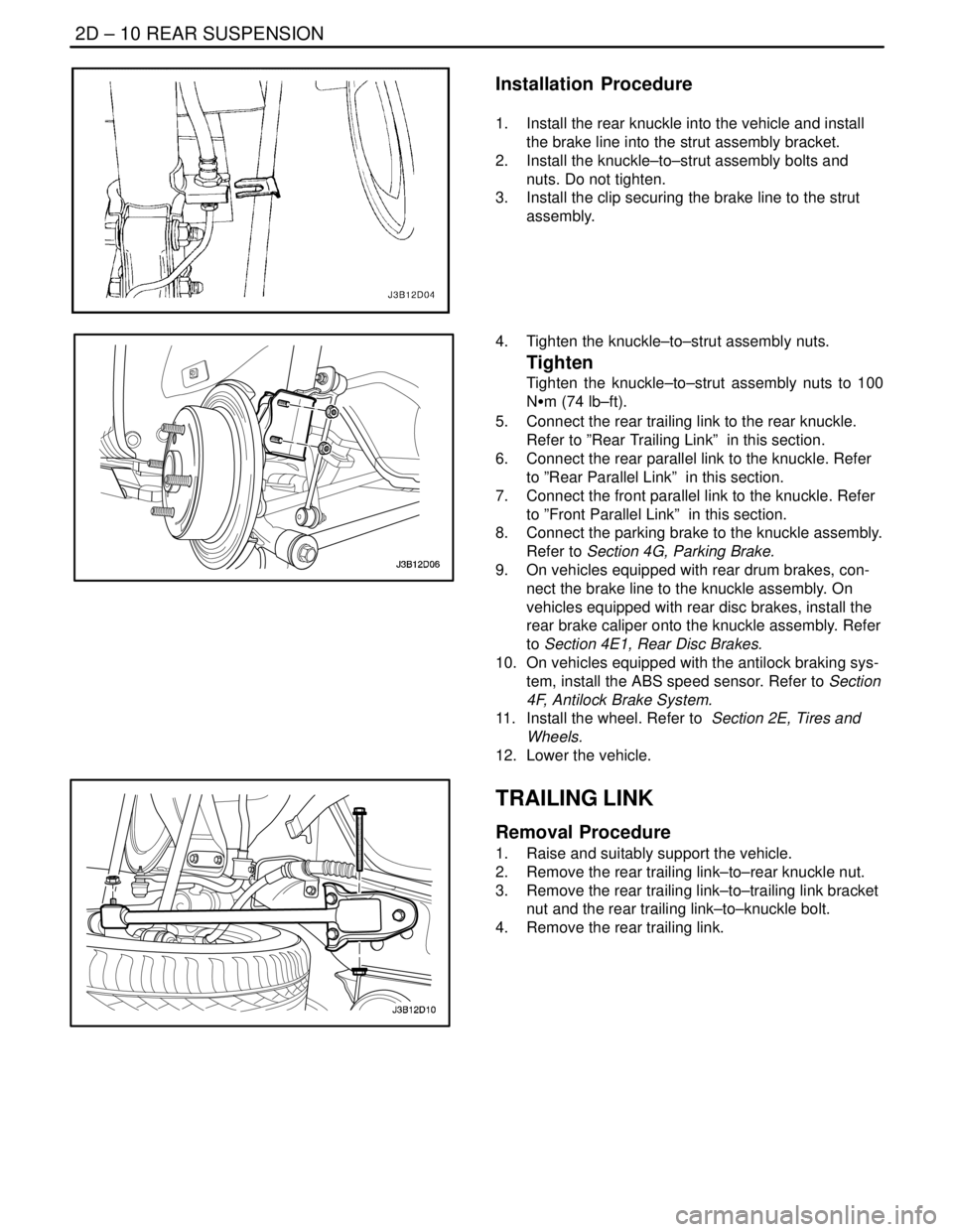
2D – 10IREAR SUSPENSION
DAEWOO V–121 BL4
Installation Procedure
1. Install the rear knuckle into the vehicle and install
the brake line into the strut assembly bracket.
2. Install the knuckle–to–strut assembly bolts and
nuts. Do not tighten.
3. Install the clip securing the brake line to the strut
assembly.
4. Tighten the knuckle–to–strut assembly nuts.
Tighten
Tighten the knuckle–to–strut assembly nuts to 100
NSm (74 lb–ft).
5. Connect the rear trailing link to the rear knuckle.
Refer to ”Rear Trailing Link” in this section.
6. Connect the rear parallel link to the knuckle. Refer
to ”Rear Parallel Link” in this section.
7. Connect the front parallel link to the knuckle. Refer
to ”Front Parallel Link” in this section.
8. Connect the parking brake to the knuckle assembly.
Refer to Section 4G, Parking Brake.
9. On vehicles equipped with rear drum brakes, con-
nect the brake line to the knuckle assembly. On
vehicles equipped with rear disc brakes, install the
rear brake caliper onto the knuckle assembly. Refer
to Section 4E1, Rear Disc Brakes.
10. On vehicles equipped with the antilock braking sys-
tem, install the ABS speed sensor. Refer to Section
4F, Antilock Brake System.
11. Install the wheel. Refer to Section 2E, Tires and
Wheels.
12. Lower the vehicle.
TRAILING LINK
Removal Procedure
1. Raise and suitably support the vehicle.
2. Remove the rear trailing link–to–rear knuckle nut.
3. Remove the rear trailing link–to–trailing link bracket
nut and the rear trailing link–to–knuckle bolt.
4. Remove the rear trailing link.
Page 957 of 2643
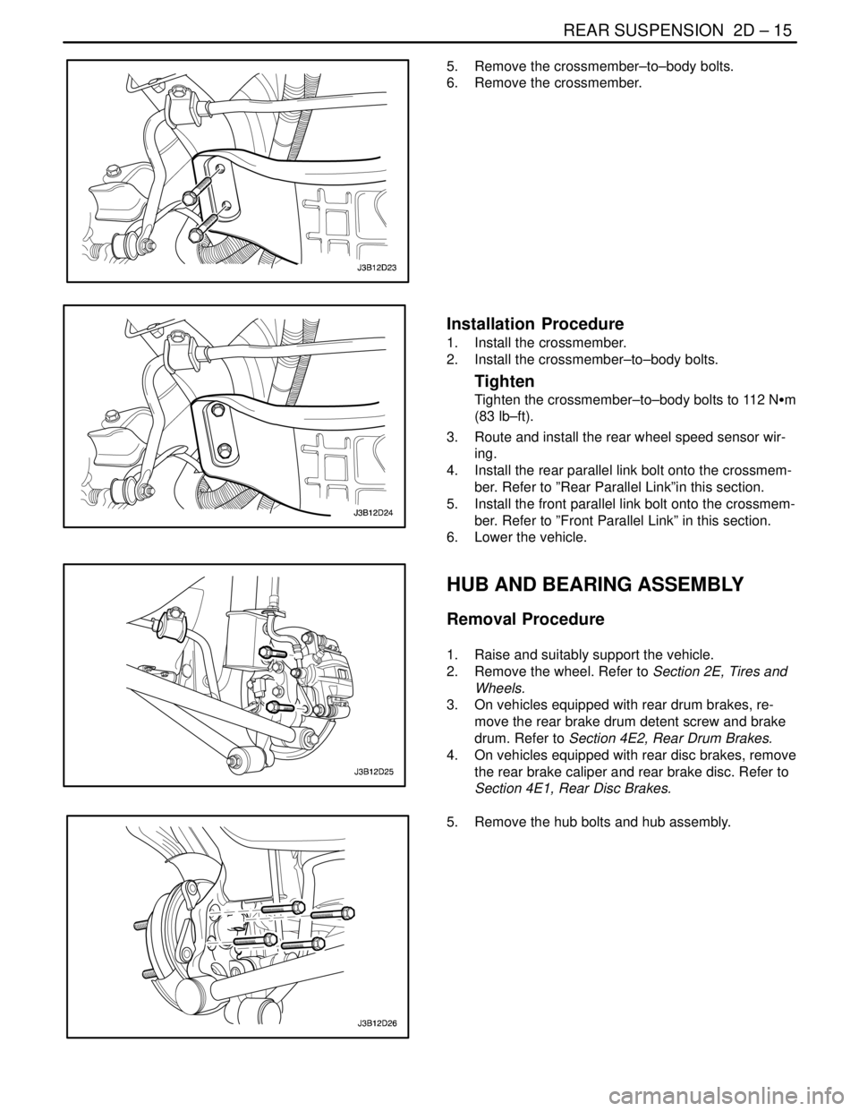
REAR SUSPENSION 2D – 15
DAEWOO V–121 BL4
5. Remove the crossmember–to–body bolts.
6. Remove the crossmember.
Installation Procedure
1. Install the crossmember.
2. Install the crossmember–to–body bolts.
Tighten
Tighten the crossmember–to–body bolts to 112 NSm
(83 lb–ft).
3. Route and install the rear wheel speed sensor wir-
ing.
4. Install the rear parallel link bolt onto the crossmem-
ber. Refer to ”Rear Parallel Link”in this section.
5. Install the front parallel link bolt onto the crossmem-
ber. Refer to ”Front Parallel Link” in this section.
6. Lower the vehicle.
HUB AND BEARING ASSEMBLY
Removal Procedure
1. Raise and suitably support the vehicle.
2. Remove the wheel. Refer to Section 2E, Tires and
Wheels.
3. On vehicles equipped with rear drum brakes, re-
move the rear brake drum detent screw and brake
drum. Refer to Section 4E2, Rear Drum Brakes.
4. On vehicles equipped with rear disc brakes, remove
the rear brake caliper and rear brake disc. Refer to
Section 4E1, Rear Disc Brakes.
5. Remove the hub bolts and hub assembly.
Page 958 of 2643
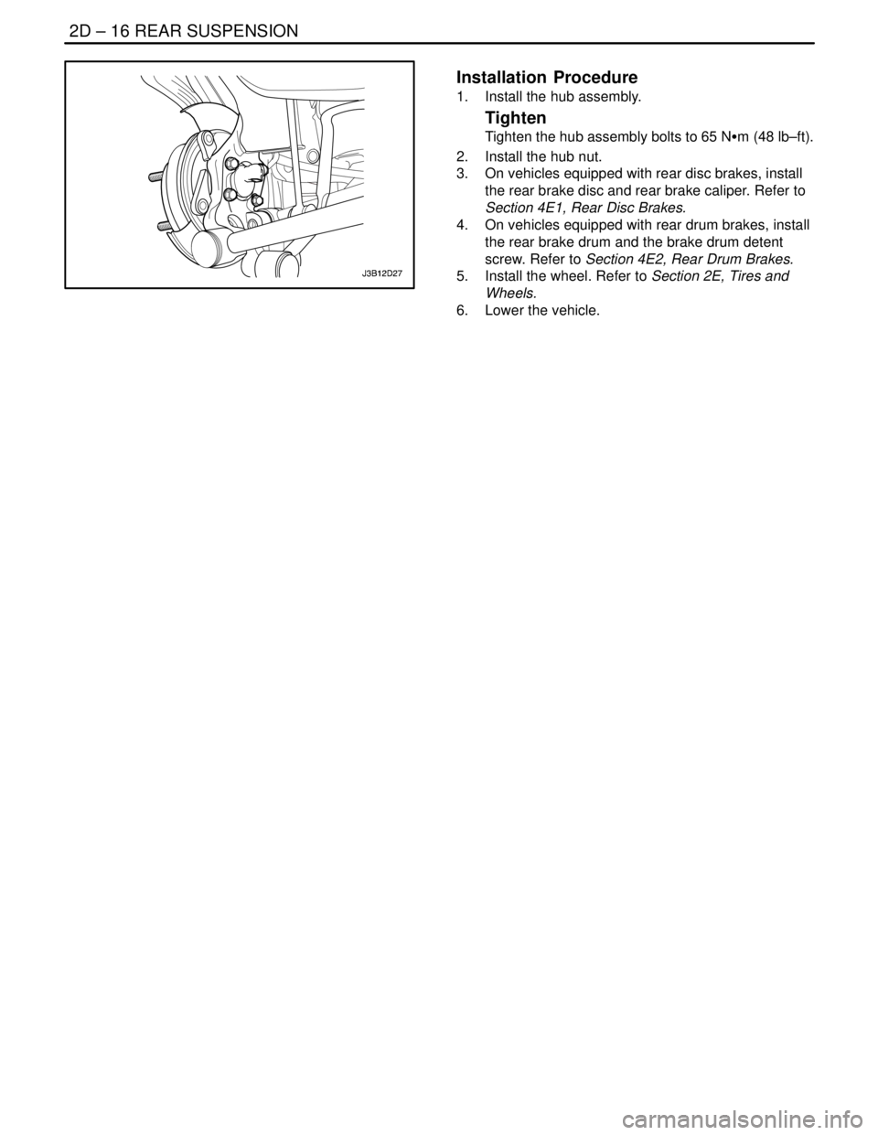
2D – 16IREAR SUSPENSION
DAEWOO V–121 BL4
Installation Procedure
1. Install the hub assembly.
Tighten
Tighten the hub assembly bolts to 65 NSm (48 lb–ft).
2. Install the hub nut.
3. On vehicles equipped with rear disc brakes, install
the rear brake disc and rear brake caliper. Refer to
Section 4E1, Rear Disc Brakes.
4. On vehicles equipped with rear drum brakes, install
the rear brake drum and the brake drum detent
screw. Refer to Section 4E2, Rear Drum Brakes.
5. Install the wheel. Refer to Section 2E, Tires and
Wheels.
6. Lower the vehicle.
Page 960 of 2643
2D – 18IREAR SUSPENSION
DAEWOO V–121 BL4
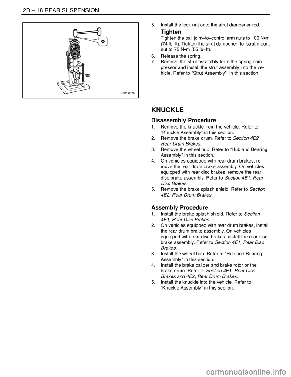
5. Install the lock nut onto the strut dampener rod.
Tighten
Tighten the ball joint–to–control arm nuts to 100 NSm
(74 lb–ft). Tighten the strut dampener–to–strut mount
nut to 75 NSm (55 lb–ft).
6. Release the spring.
7. Remove the strut assembly from the spring com-
pressor and install the strut assembly into the ve-
hicle. Refer to ”Strut Assembly” in this section.
KNUCKLE
Disassembly Procedure
1. Remove the knuckle from the vehicle. Refer to
”Knuckle Assembly” in this section.
2. Remove the brake drum. Refer to Section 4E2,
Rear Drum Brakes.
3. Remove the wheel hub. Refer to ”Hub and Bearing
Assembly” in this section.
4. On vehicles equipped with rear drum brakes, re-
move the rear drum brake assembly. On vehicles
equipped with rear disc brakes, remove the rear
disc brake assembly. Refer to Section 4E1, Rear
Disc Brakes.
5. Remove the brake splash shield. Refer to Section
4E2, Rear Drum Brakes.
Assembly Procedure
1. Install the brake splash shield. Refer to Section
4E1, Rear Disc Brakes.
2. On vehicles equipped with rear drum brakes, install
the rear drum brake assembly. On vehicles
equipped with rear disc brakes, install the rear disc
brake assembly. Refer to Section 4E1, Rear Disc
Brakes.
3. Install the wheel hub. Refer to ”Hub and Bearing
Assembly” in this section.
4. Install the brake caliper and brake rotor or the
brake drum. Refer to Section 4E1, Rear Disc
Brakes and 4E2, Rear Drum Brakes.
5. Install the knuckle into the vehicle. Refer to
”Knuckle Assembly” in this section.