brakes DAEWOO LACETTI 2004 Service Owner's Guide
[x] Cancel search | Manufacturer: DAEWOO, Model Year: 2004, Model line: LACETTI, Model: DAEWOO LACETTI 2004Pages: 2643, PDF Size: 80.54 MB
Page 1027 of 2643
HYDRAULIC BRAKES 4A – 11
DAEWOO V–121 BL4
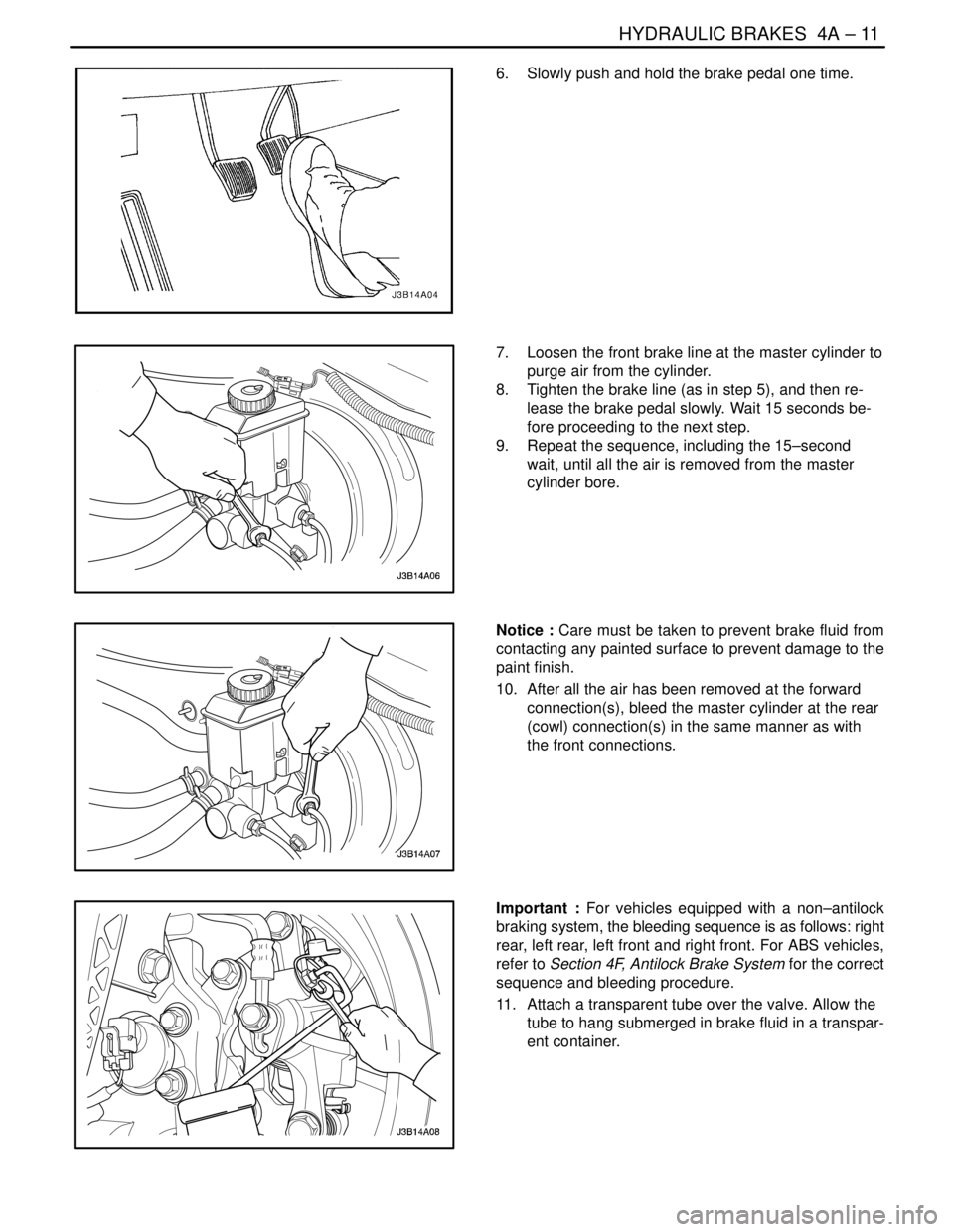
6. Slowly push and hold the brake pedal one time.
7. Loosen the front brake line at the master cylinder to
purge air from the cylinder.
8. Tighten the brake line (as in step 5), and then re-
lease the brake pedal slowly. Wait 15 seconds be-
fore proceeding to the next step.
9. Repeat the sequence, including the 15–second
wait, until all the air is removed from the master
cylinder bore.
Notice : Care must be taken to prevent brake fluid from
contacting any painted surface to prevent damage to the
paint finish.
10. After all the air has been removed at the forward
connection(s), bleed the master cylinder at the rear
(cowl) connection(s) in the same manner as with
the front connections.
Important : For vehicles equipped with a non–antilock
braking system, the bleeding sequence is as follows: right
rear, left rear, left front and right front. For ABS vehicles,
refer to Section 4F, Antilock Brake System for the correct
sequence and bleeding procedure.
11. Attach a transparent tube over the valve. Allow the
tube to hang submerged in brake fluid in a transpar-
ent container.
Page 1028 of 2643
4A – 12IHYDRAULIC BRAKES
DAEWOO V–121 BL4
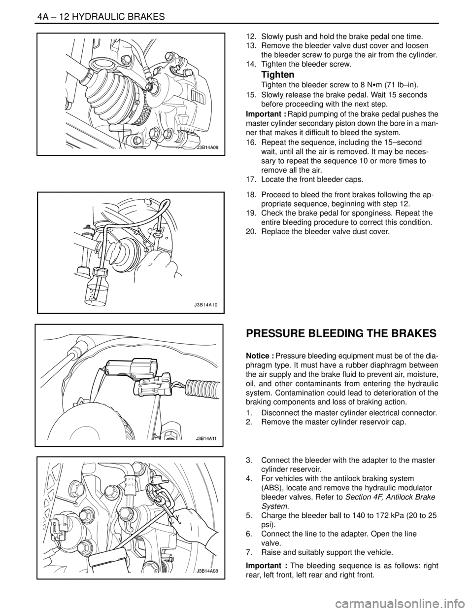
12. Slowly push and hold the brake pedal one time.
13. Remove the bleeder valve dust cover and loosen
the bleeder screw to purge the air from the cylinder.
14. Tighten the bleeder screw.
Tighten
Tighten the bleeder screw to 8 NSm (71 lb–in).
15. Slowly release the brake pedal. Wait 15 seconds
before proceeding with the next step.
Important : Rapid pumping of the brake pedal pushes the
master cylinder secondary piston down the bore in a man-
ner that makes it difficult to bleed the system.
16. Repeat the sequence, including the 15–second
wait, until all the air is removed. It may be neces-
sary to repeat the sequence 10 or more times to
remove all the air.
17. Locate the front bleeder caps.
18. Proceed to bleed the front brakes following the ap-
propriate sequence, beginning with step 12.
19. Check the brake pedal for sponginess. Repeat the
entire bleeding procedure to correct this condition.
20. Replace the bleeder valve dust cover.
PRESSURE BLEEDING THE BRAKES
Notice : Pressure bleeding equipment must be of the dia-
phragm type. It must have a rubber diaphragm between
the air supply and the brake fluid to prevent air, moisture,
oil, and other contaminants from entering the hydraulic
system. Contamination could lead to deterioration of the
braking components and loss of braking action.
1. Disconnect the master cylinder electrical connector.
2. Remove the master cylinder reservoir cap.
3. Connect the bleeder with the adapter to the master
cylinder reservoir.
4. For vehicles with the antilock braking system
(ABS), locate and remove the hydraulic modulator
bleeder valves. Refer to Section 4F, Antilock Brake
System.
5. Charge the bleeder ball to 140 to 172 kPa (20 to 25
psi).
6. Connect the line to the adapter. Open the line
valve.
7. Raise and suitably support the vehicle.
Important : The bleeding sequence is as follows: right
rear, left front, left rear and right front.
Page 1029 of 2643
HYDRAULIC BRAKES 4A – 13
DAEWOO V–121 BL4
8. Attach the bleeder hose to the bleeder valve. Sub-
merge the opposite end of the hose in a clean con-
tainer partially filled with brake fluid.
9. Open the bleeder valve one–half to three–fourths
turn and allow the fluid to flow until no air is seen in
the fluid.
Notice : After the bleeding operation, the brake reservoir
may be pressurized. While disconnecting the bleeder
hose or the unthreaded adapter cap, cover the cap and the
connection with a shop towel to protect painted surfaces
from contact with the brake fluid.
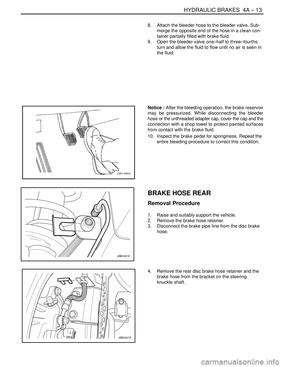
10. Inspect the brake pedal for sponginess. Repeat the
entire bleeding procedure to correct this condition.
BRAKE HOSE REAR
Removal Procedure
1. Raise and suitably support the vehicle.
2. Remove the brake hose retainer.
3. Disconnect the brake pipe line from the disc brake
hose.
4. Remove the rear disc brake hose retainer and the
brake hose from the bracket on the steering
knuckle shaft.
Page 1030 of 2643
4A – 14IHYDRAULIC BRAKES
DAEWOO V–121 BL4
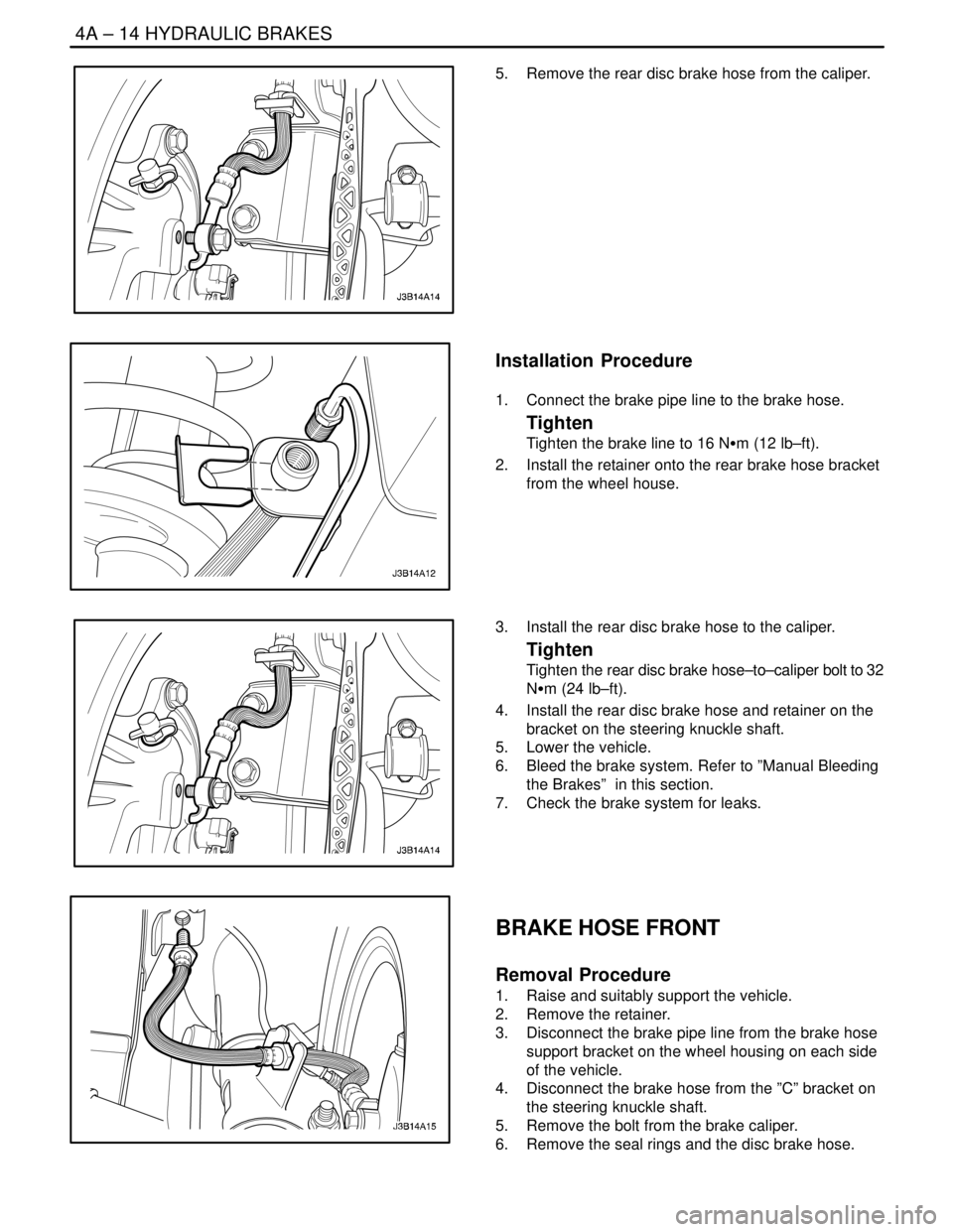
5. Remove the rear disc brake hose from the caliper.
Installation Procedure
1. Connect the brake pipe line to the brake hose.
Tighten
Tighten the brake line to 16 NSm (12 lb–ft).
2. Install the retainer onto the rear brake hose bracket
from the wheel house.
3. Install the rear disc brake hose to the caliper.
Tighten
Tighten the rear disc brake hose–to–caliper bolt to 32
NSm (24 lb–ft).
4. Install the rear disc brake hose and retainer on the
bracket on the steering knuckle shaft.
5. Lower the vehicle.
6. Bleed the brake system. Refer to ”Manual Bleeding
the Brakes” in this section.
7. Check the brake system for leaks.
BRAKE HOSE FRONT
Removal Procedure
1. Raise and suitably support the vehicle.
2. Remove the retainer.
3. Disconnect the brake pipe line from the brake hose
support bracket on the wheel housing on each side
of the vehicle.
4. Disconnect the brake hose from the ”C” bracket on
the steering knuckle shaft.
5. Remove the bolt from the brake caliper.
6. Remove the seal rings and the disc brake hose.
Page 1031 of 2643
HYDRAULIC BRAKES 4A – 15
DAEWOO V–121 BL4
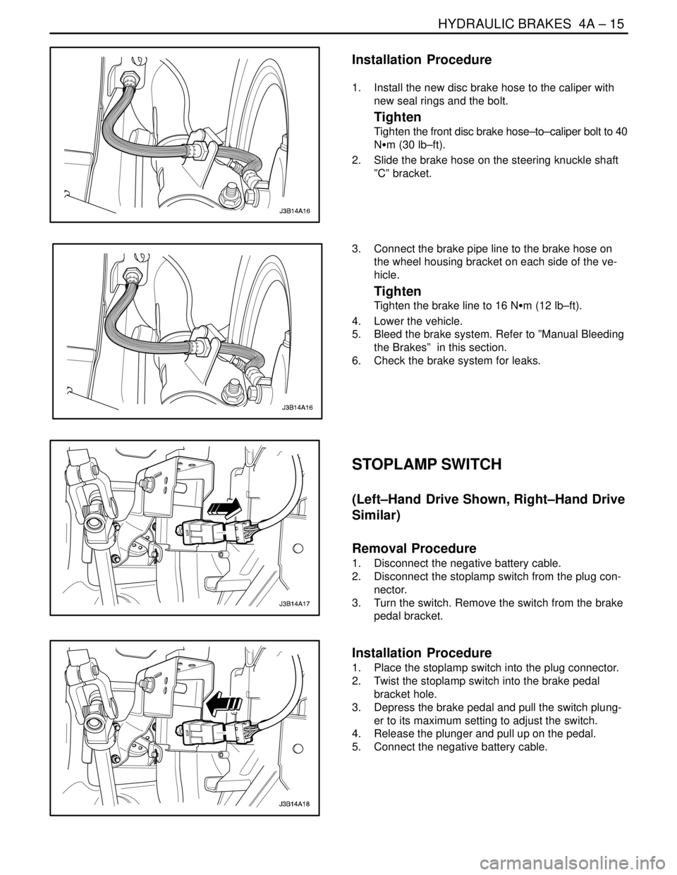
Installation Procedure
1. Install the new disc brake hose to the caliper with
new seal rings and the bolt.
Tighten
Tighten the front disc brake hose–to–caliper bolt to 40
NSm (30 lb–ft).
2. Slide the brake hose on the steering knuckle shaft
”C” bracket.
3. Connect the brake pipe line to the brake hose on
the wheel housing bracket on each side of the ve-
hicle.
Tighten
Tighten the brake line to 16 NSm (12 lb–ft).
4. Lower the vehicle.
5. Bleed the brake system. Refer to ”Manual Bleeding
the Brakes” in this section.
6. Check the brake system for leaks.
STOPLAMP SWITCH
(Left–Hand Drive Shown, Right–Hand Drive
Similar)
Removal Procedure
1. Disconnect the negative battery cable.
2. Disconnect the stoplamp switch from the plug con-
nector.
3. Turn the switch. Remove the switch from the brake
pedal bracket.
Installation Procedure
1. Place the stoplamp switch into the plug connector.
2. Twist the stoplamp switch into the brake pedal
bracket hole.
3. Depress the brake pedal and pull the switch plung-
er to its maximum setting to adjust the switch.
4. Release the plunger and pull up on the pedal.
5. Connect the negative battery cable.
Page 1032 of 2643
4A – 16IHYDRAULIC BRAKES
DAEWOO V–121 BL4
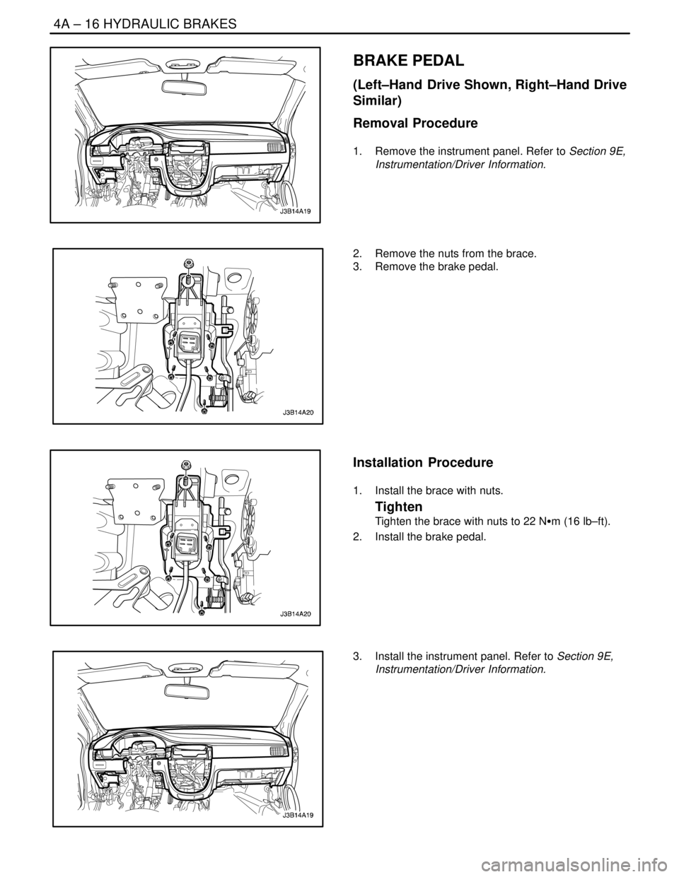
BRAKE PEDAL
(Left–Hand Drive Shown, Right–Hand Drive
Similar)
Removal Procedure
1. Remove the instrument panel. Refer to Section 9E,
Instrumentation/Driver Information.
2. Remove the nuts from the brace.
3. Remove the brake pedal.
Installation Procedure
1. Install the brace with nuts.
Tighten
Tighten the brace with nuts to 22 NSm (16 lb–ft).
2. Install the brake pedal.
3. Install the instrument panel. Refer to Section 9E,
Instrumentation/Driver Information.
Page 1033 of 2643

HYDRAULIC BRAKES 4A – 17
DAEWOO V–121 BL4
GENERAL DESCRIPTION
AND SYSTEM OPERATION
WARNING LAMP OPERATION
This brake system uses a BRAKE warning lamp located
in the instrument panel cluster. When the ignition switch
is in the START position, the BRAKE warning lamp should
illuminate. It should go off when the ignition switch returns
to the ON position.The following conditions will activate the BRAKE warning
lamp:
S The lamp should be on whenever the parking brake
is applied and the ignition switch is in the ON posi-
tion.
S A low fluid level in the master cylinder will turn the
BRAKE lamp on.
Page 1035 of 2643

4B – 2IMASTER CYLINDER
DAEWOO V–121 BL4
DIAGNOSIS
CHECKING BRAKE
PROPORTIONING VALVE
Use two brake pressure gauges to check the brake pro-
portioning valves that are attached to the master cylinder
on non–ABS braking systems. These valves limit the out-
let pressure to the rear brakes after a predetermined mas-
ter cylinder pressure has been reached. (On ABS braking
systems, the hydraulic modulator/motor pack assembly
controls the hydraulic pressure to both the rear wheel cyl-
inders or rear calipers, and the front calipers.)
When checking the brake proportioning valves, be sure
that the hydraulic line pressure is measured simulta-
neously and diagonally on the front and the rear axles.To measure the pressure, use the following steps.
1. Remove the bleeder valve and install a pressure
gauge to one of the rear brake cylinders.
2. Install another bleeder valve and install another
pressure gauge to the diagonally opposite front
brake.
3. Build pressure by pressing firmly on the brake ped-
al several times. (The pressure indicated on the
gauge is not regulated and represents the actual
brake system hydraulic pressure.)
4. Build pressure until the test values in the following
proportioning valve test chart are achieved.
Model
Reference Number for
Gradient and Switching
Pressure on the Valve
HousingInput Pressure Read on
the Manometer at the
Front Axle in kPa (psi)Output Pressure Read
on the Manometer at the
Front Axle in kPa (psi)
500 (73)500 (73)
N/B, H/B0.3/304 500 (653) 3 450 ± 200(500 ± 29)
10 000 (1,450)5 100 ± 300(740 ± 44)
500 (73)500 (73)
WAGON0.3/405 500 (798)4 450 ± 200(645 ± 29)
10 000 (1,450)5 800 ± 300(841 ± 44)
Important : If the pressure exceeds 10 000 kPa (1,450
psi), the pressure reading on the rear gauge will not be ac-
curate.5. Remove the gauges from the tested brake circuit
and repeat the test on the remaining circuit.
Page 1037 of 2643
4B – 4IMASTER CYLINDER
DAEWOO V–121 BL4
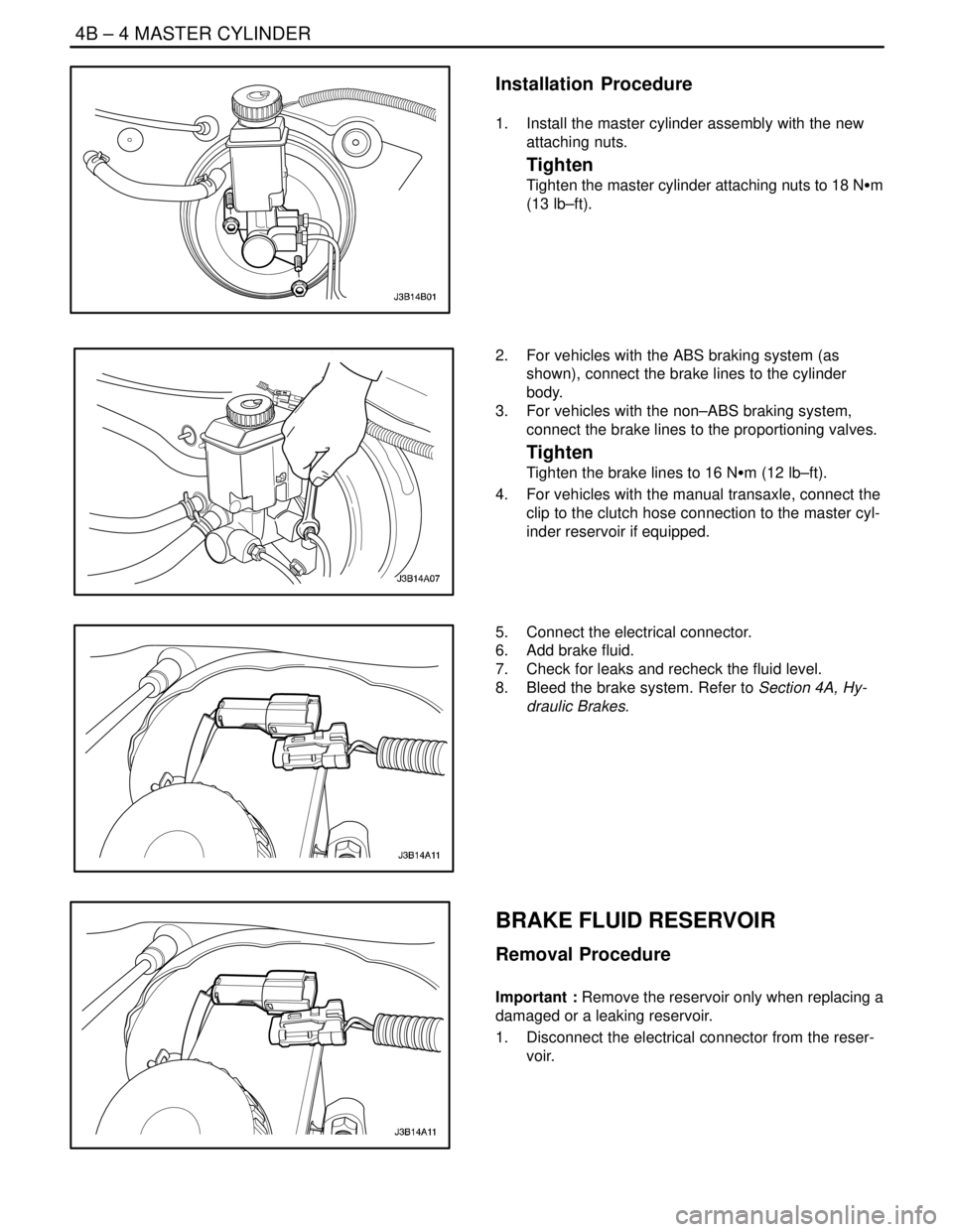
Installation Procedure
1. Install the master cylinder assembly with the new
attaching nuts.
Tighten
Tighten the master cylinder attaching nuts to 18 NSm
(13 lb–ft).
2. For vehicles with the ABS braking system (as
shown), connect the brake lines to the cylinder
body.
3. For vehicles with the non–ABS braking system,
connect the brake lines to the proportioning valves.
Tighten
Tighten the brake lines to 16 NSm (12 lb–ft).
4. For vehicles with the manual transaxle, connect the
clip to the clutch hose connection to the master cyl-
inder reservoir if equipped.
5. Connect the electrical connector.
6. Add brake fluid.
7. Check for leaks and recheck the fluid level.
8. Bleed the brake system. Refer to Section 4A, Hy-
draulic Brakes.
BRAKE FLUID RESERVOIR
Removal Procedure
Important : Remove the reservoir only when replacing a
damaged or a leaking reservoir.
1. Disconnect the electrical connector from the reser-
voir.
Page 1039 of 2643
4B – 6IMASTER CYLINDER
DAEWOO V–121 BL4
4. Add brake fluid.
5. Raise and suitably support the vehicle.
6. Bleed the braking system. Refer to Section 4A, Hy-
draulic Brakes orSection 4F, Antilock Brake Sys-
tem.Bleed the clutch master cylinder. Refer to Sec-
tion 5C, Clutch.
7. Lower the vehicle.
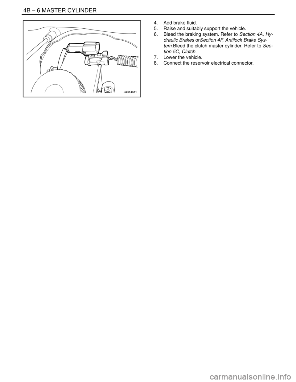
8. Connect the reservoir electrical connector.