DAEWOO LACETTI 2004 Service Repair Manual
Manufacturer: DAEWOO, Model Year: 2004, Model line: LACETTI, Model: DAEWOO LACETTI 2004Pages: 2643, PDF Size: 80.54 MB
Page 2361 of 2643
SEATS 9H – 5
DAEWOO V–121 BL4
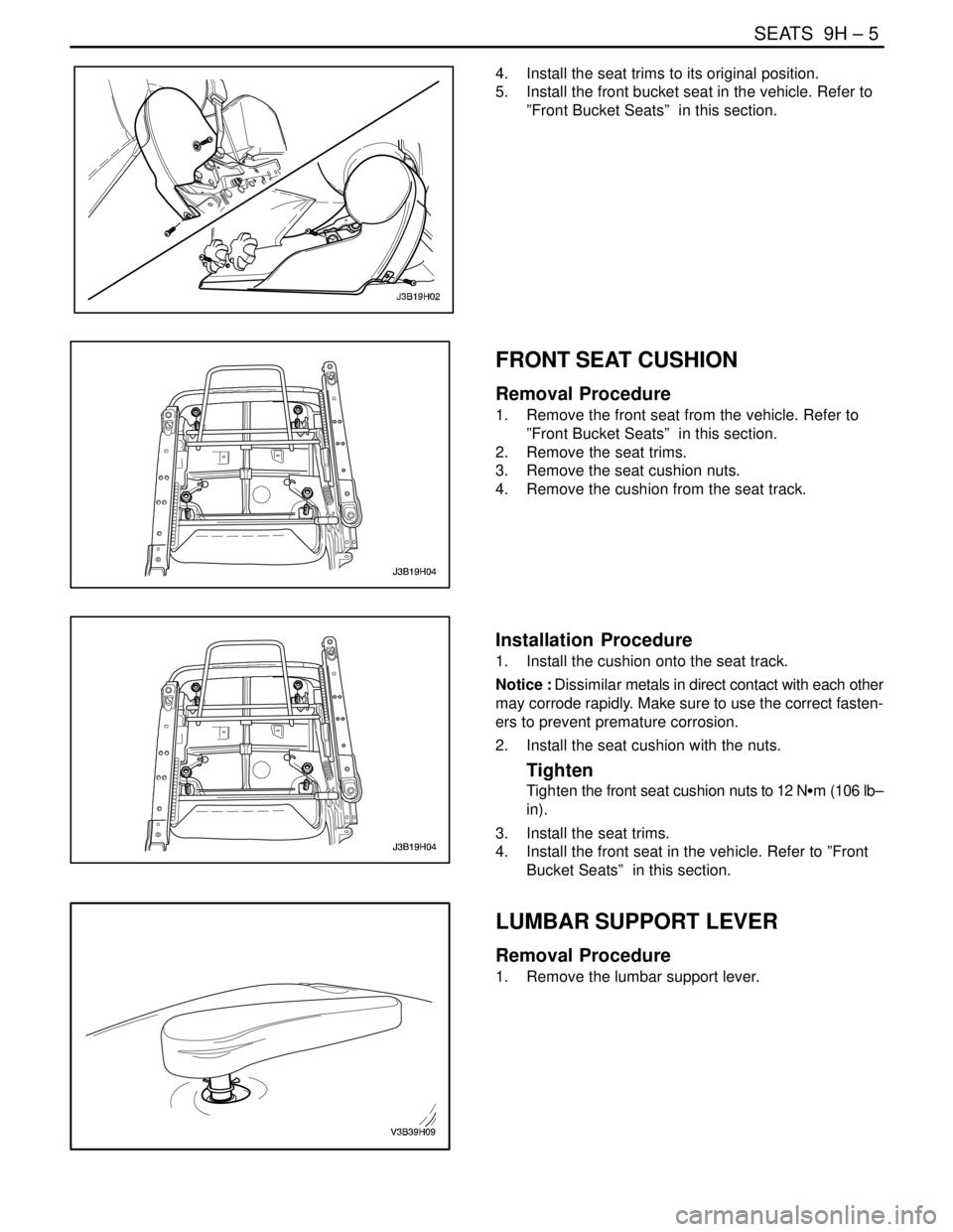
4. Install the seat trims to its original position.
5. Install the front bucket seat in the vehicle. Refer to
”Front Bucket Seats” in this section.
FRONT SEAT CUSHION
Removal Procedure
1. Remove the front seat from the vehicle. Refer to
”Front Bucket Seats” in this section.
2. Remove the seat trims.
3. Remove the seat cushion nuts.
4. Remove the cushion from the seat track.
Installation Procedure
1. Install the cushion onto the seat track.
Notice : Dissimilar metals in direct contact with each other
may corrode rapidly. Make sure to use the correct fasten-
ers to prevent premature corrosion.
2. Install the seat cushion with the nuts.
Tighten
Tighten the front seat cushion nuts to 12 NSm (106 lb–
in).
3. Install the seat trims.
4. Install the front seat in the vehicle. Refer to ”Front
Bucket Seats” in this section.
LUMBAR SUPPORT LEVER
Removal Procedure
1. Remove the lumbar support lever.
Page 2362 of 2643
9H – 6ISEATS
DAEWOO V–121 BL4
Installation Procedure
Notice : Dissimilar metals in direct contact with each other
may corrode rapidly. Make sure to use the correct fasten-
ers to prevent premature corrosion.
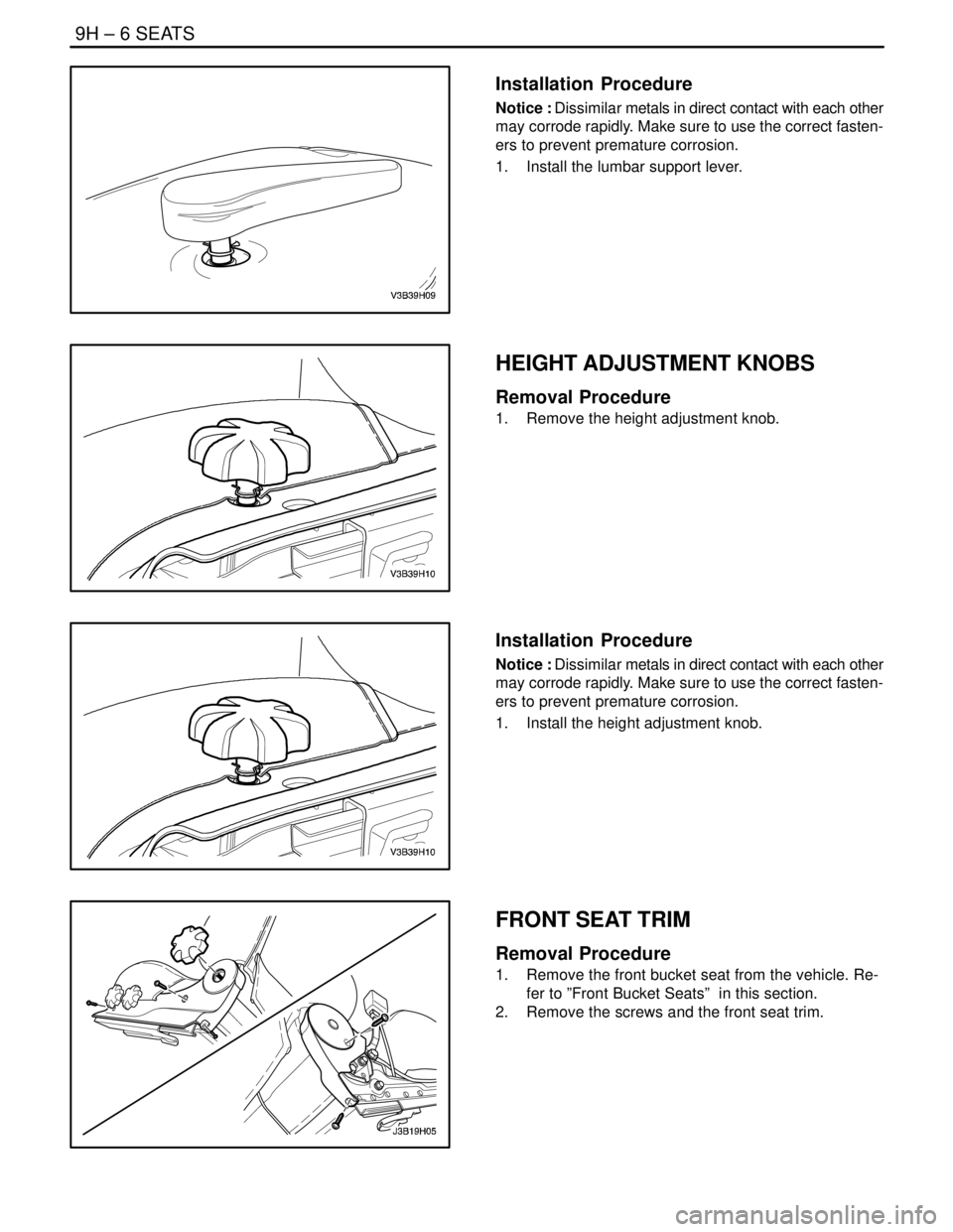
1. Install the lumbar support lever.
HEIGHT ADJUSTMENT KNOBS
Removal Procedure
1. Remove the height adjustment knob.
Installation Procedure
Notice : Dissimilar metals in direct contact with each other
may corrode rapidly. Make sure to use the correct fasten-
ers to prevent premature corrosion.
1. Install the height adjustment knob.
FRONT SEAT TRIM
Removal Procedure
1. Remove the front bucket seat from the vehicle. Re-
fer to ”Front Bucket Seats” in this section.
2. Remove the screws and the front seat trim.
Page 2363 of 2643
SEATS 9H – 7
DAEWOO V–121 BL4
Installation Procedure
Notice : Dissimilar metals in direct contact with each other
may corrode rapidly. Make sure to use the correct fasten-
ers to prevent premature corrosion.
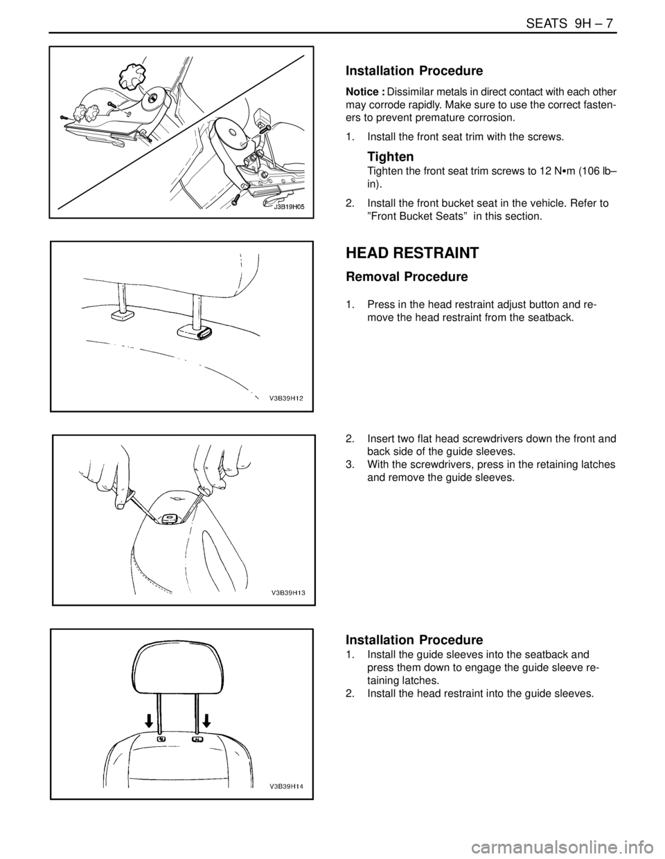
1. Install the front seat trim with the screws.
Tighten
Tighten the front seat trim screws to 12 NSm (106 lb–
in).
2. Install the front bucket seat in the vehicle. Refer to
”Front Bucket Seats” in this section.
HEAD RESTRAINT
Removal Procedure
1. Press in the head restraint adjust button and re-
move the head restraint from the seatback.
2. Insert two flat head screwdrivers down the front and
back side of the guide sleeves.
3. With the screwdrivers, press in the retaining latches
and remove the guide sleeves.
Installation Procedure
1. Install the guide sleeves into the seatback and
press them down to engage the guide sleeve re-
taining latches.
2. Install the head restraint into the guide sleeves.
Page 2364 of 2643
9H – 8ISEATS
DAEWOO V–121 BL4
REAR SEAT CUSHION
Removal Procedure
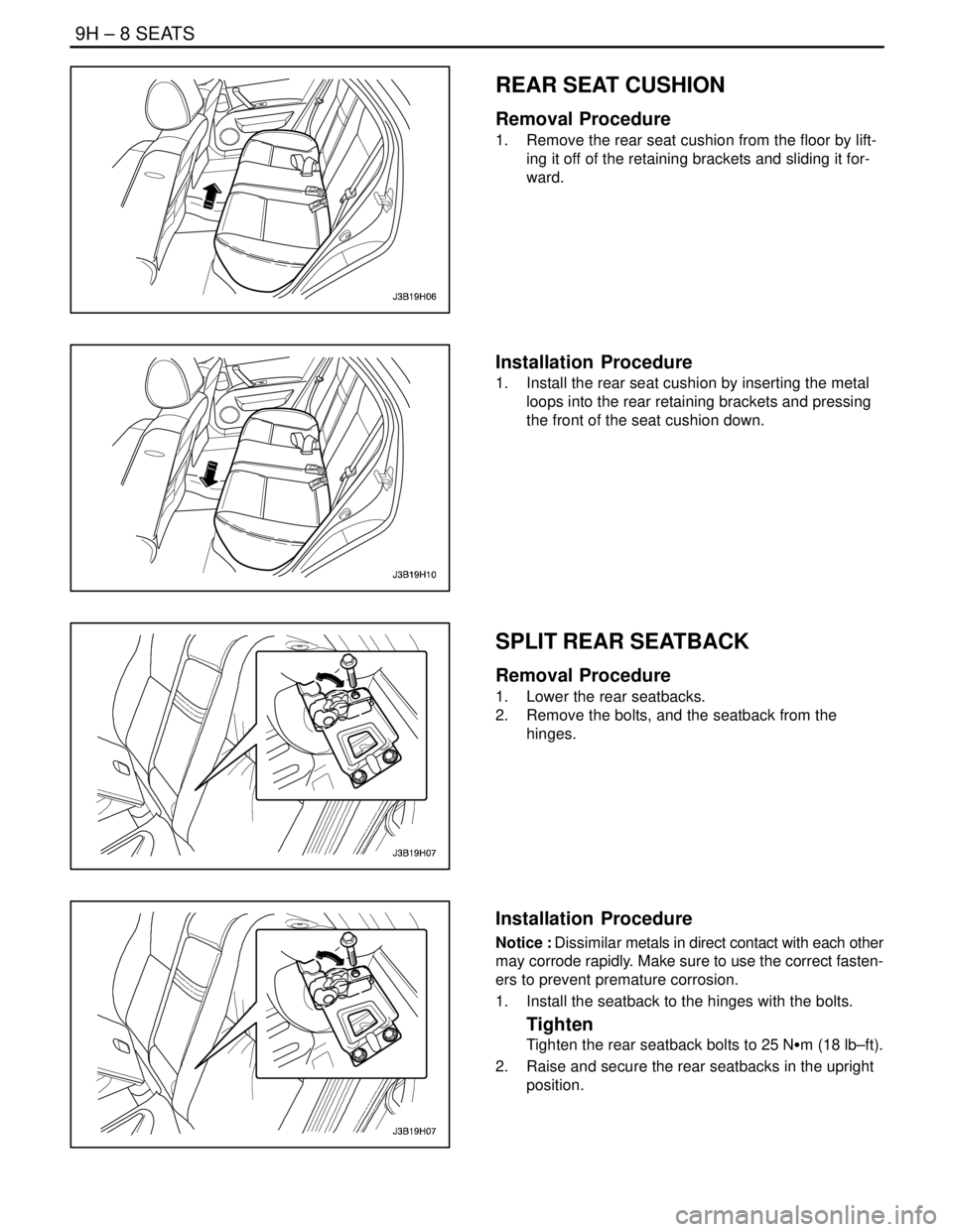
1. Remove the rear seat cushion from the floor by lift-
ing it off of the retaining brackets and sliding it for-
ward.
Installation Procedure
1. Install the rear seat cushion by inserting the metal
loops into the rear retaining brackets and pressing
the front of the seat cushion down.
SPLIT REAR SEATBACK
Removal Procedure
1. Lower the rear seatbacks.
2. Remove the bolts, and the seatback from the
hinges.
Installation Procedure
Notice : Dissimilar metals in direct contact with each other
may corrode rapidly. Make sure to use the correct fasten-
ers to prevent premature corrosion.
1. Install the seatback to the hinges with the bolts.
Tighten
Tighten the rear seatback bolts to 25 NSm (18 lb–ft).
2. Raise and secure the rear seatbacks in the upright
position.
Page 2365 of 2643
SEATS 9H – 9
DAEWOO V–121 BL4
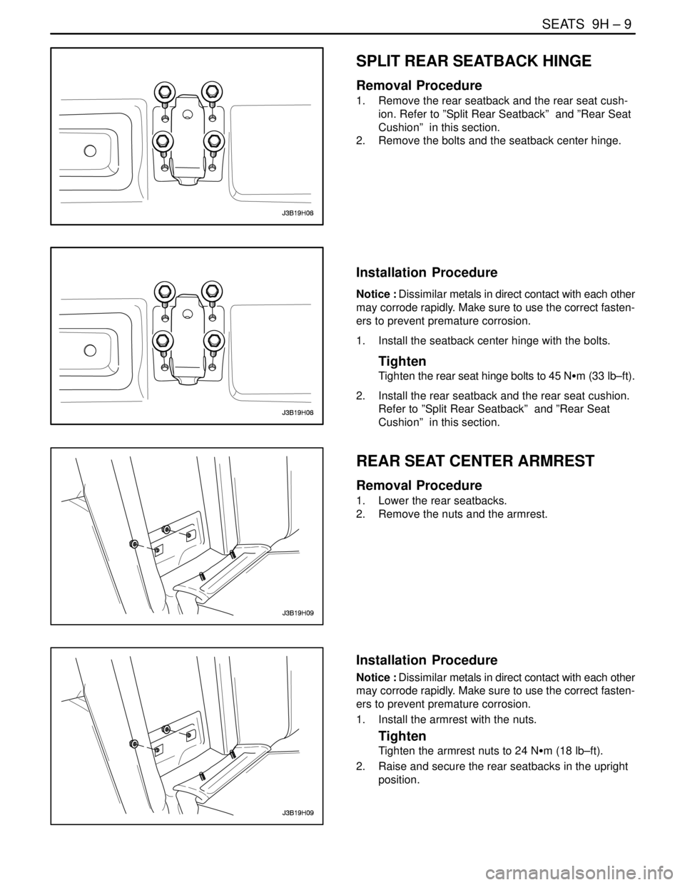
SPLIT REAR SEATBACK HINGE
Removal Procedure
1. Remove the rear seatback and the rear seat cush-
ion. Refer to ”Split Rear Seatback” and ”Rear Seat
Cushion” in this section.
2. Remove the bolts and the seatback center hinge.
Installation Procedure
Notice : Dissimilar metals in direct contact with each other
may corrode rapidly. Make sure to use the correct fasten-
ers to prevent premature corrosion.
1. Install the seatback center hinge with the bolts.
Tighten
Tighten the rear seat hinge bolts to 45 NSm (33 lb–ft).
2. Install the rear seatback and the rear seat cushion.
Refer to ”Split Rear Seatback” and ”Rear Seat
Cushion” in this section.
REAR SEAT CENTER ARMREST
Removal Procedure
1. Lower the rear seatbacks.
2. Remove the nuts and the armrest.
Installation Procedure
Notice : Dissimilar metals in direct contact with each other
may corrode rapidly. Make sure to use the correct fasten-
ers to prevent premature corrosion.
1. Install the armrest with the nuts.
Tighten
Tighten the armrest nuts to 24 NSm (18 lb–ft).
2. Raise and secure the rear seatbacks in the upright
position.
Page 2366 of 2643
9H – 10ISEATS
DAEWOO V–121 BL4
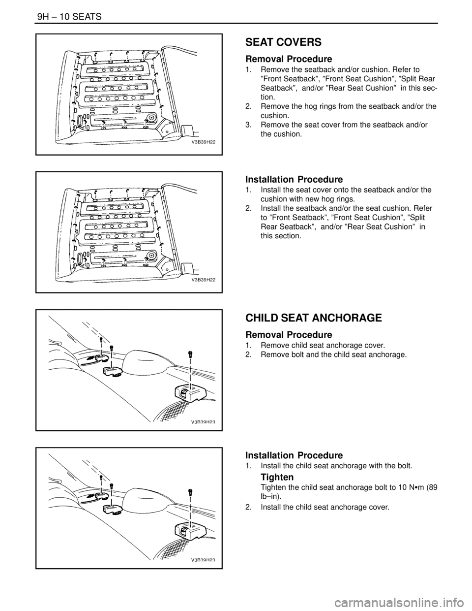
SEAT COVERS
Removal Procedure
1. Remove the seatback and/or cushion. Refer to
”Front Seatback”, ”Front Seat Cushion”, ”Split Rear
Seatback”, and/or ”Rear Seat Cushion” in this sec-
tion.
2. Remove the hog rings from the seatback and/or the
cushion.
3. Remove the seat cover from the seatback and/or
the cushion.
Installation Procedure
1. Install the seat cover onto the seatback and/or the
cushion with new hog rings.
2. Install the seatback and/or the seat cushion. Refer
to ”Front Seatback”, ”Front Seat Cushion”, ”Split
Rear Seatback”, and/or ”Rear Seat Cushion” in
this section.
CHILD SEAT ANCHORAGE
Removal Procedure
1. Remove child seat anchorage cover.
2. Remove bolt and the child seat anchorage.
Installation Procedure
1. Install the child seat anchorage with the bolt.
Tighten
Tighten the child seat anchorage bolt to 10 NSm (89
lb–in).
2. Install the child seat anchorage cover.
Page 2367 of 2643

SEATS 9H – 11
DAEWOO V–121 BL4
HATCHBACK CHILD SEAT
ANCHORAGE
Removal Procedure
1. Remove child seat anchorage cover.
2. Remove bolt and the child seat anchorage.
Installation Procedure
1. Install the child seat anchorage with the bolt.
Tighten
Tighten the child seat anchorage bolt to 10 NSm (89
lb–in).
2. Install the child seat anchorage cover.
Page 2368 of 2643

9H – 12ISEATS
DAEWOO V–121 BL4
GENERAL DESCRIPTION
AND SYSTEM OPERATION
SEATS
Do not attempt to change the designed seat position by al-
tering the designed seat adjuster–to–floor pan anchor pro-
visions or the seat adjuster–to–seat frame anchor provi-
sions. Changing the seat position could affect the
performance of the seat system.This vehicle is equipped with front bucket seats with sepa-
rate, adjustable head restraints, and a three–passenger
rear bench seat with an optional split folding rear seat. The
front bucket seats also have a recline, a height, and a lum-
bar adjustment. A power driver seat is optional. Seat cush-
ions and seatbacks have formed foam pads, which fit the
contours of the full panel seatback frame assembly and
the designed contour of the seat cushion frame.
Page 2369 of 2643

SECTION : 9I
WATERLEAKS
TABLE OF CONTENTS
SPECIFICATIONS9I–1 . . . . . . . . . . . . . . . . . . . . . . . . . . .
Recommended Materials for Waterleak Repairs 9I–1.
Watertest Stand Specifications 9I–1. . . . . . . . . . . . . . .
DIAGNOSIS9I–2 . . . . . . . . . . . . . . . . . . . . . . . . . . . . . . . . . Waterleak Diagnosis 9I–2. . . . . . . . . . . . . . . . . . . . . . . .
MAINTENANCE AND REPAIR9I–5 . . . . . . . . . . . . . . . .
ON–VEHICLE SERVICE 9I–5. . . . . . . . . . . . . . . . . . . . . .
Waterleak Repair 9I–5. . . . . . . . . . . . . . . . . . . . . . . . . . .
SPECIFICATIONS
RECOMMENDED MATERIALS FOR WATERLEAK
REPAIRS
Leak Areas Repair Materials
Windshield, back windowUrethane adhesive, caulking kit, or the equivalent
Metal jointsBrushable seam sealer which can be painted
Ventilation ducts3Mnv Auto Bedding and Glazing Compound or the equiva-
lent
Small cracks and pin holes3Mnv Drip–Check Sealer or the equivalent
Large holes3Mnv Automotive Joint and Seam Sealer
Weatherstrips3Mnv 08011 Weatherstrip Adhesive or the equivalent
Bolts, studs, and screwsStrip caulk
WATERTEST STAND SPECIFICATIONS
ApplicationDescription
Nozzle TypeFull jet spray nozzle #1/2 GG–25 or equivalent with a 60°
included angle
Nozzle HeightApproximately 1 600 mm (63.0 in.) from the floor
Volume of Flow14L (3.7 gal) per minute
Pressure155 kPa (22.5 psi) measured at the nozzle
Windshield and A–Pillar Test Stand PositionApproximately 30° down, 45° toward the rear, and aimed
at the corner of the windshield
B–Pillar Test Stand PositionApproximately 30° down, 45° toward the rear, and aimed
at the center of the rear door
Back Window and Rear Deck Lid Test Stand PositionApproximately 30° down, 30° toward the front and aimed
approximately 610 mm (24.0 in.) from the corner of the
back window
Page 2370 of 2643
9I – 2IWATERLEAKS
DAEWOO V–121 BL4
DIAGNOSIS
WATERLEAK DIAGNOSIS
The repair of waterleaks in the body requires proper test-
ing and diagnosis. Repair waterleaks by adjusting the mis-
aligned parts and using the proper repair materials. First,
determine what conditions cause the leak. For example,
the leak may occur only when the vehicle is parked on an
incline, or water may appear only in the spare tire compart-
ment. Second, test the area for the source of the leak us-
ing the following testing methods. If the general leak area
is found, determine the exact entry point of the leak by us-
ing a water hose or an air hose. If the general leak area is
not obvious, use the watertest stands to determine the
area of the leak. It may be necessary to remove some inte-
rior trim panels or some parts in order to locate the leaks.
Important : It is necessary to find the origin of all the leaks
before making any repairs. Random repairs may stop the
leak only temporarily and may make future repairs more
difficult. Continue localized testing in the general area in
order to ensure that all leaks are found.
Generalized Testing
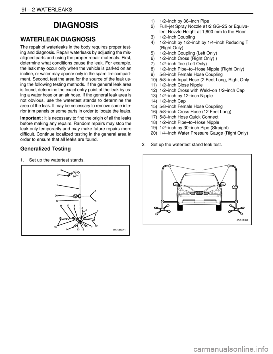
1. Set up the watertest stands.
1) 1/2–inch by 36–inch Pipe
2) Full–jet Spray Nozzle #1/2 GG–25 or Equiva-
lent Nozzle Height at 1,600 mm to the Floor
3) 1/2–inch Coupling
4) 1/2–inch by 1/2–inch by 1/4–inch Reducing T
(Right Only)
5) 1/2–inch Coupling (Left Only)
6) 1/2–inch Cross (Right Only) )
7) 1/2–inch Tee (Left Only)
8) 1/2–inch Pipe–to–Hose Nipple (Right Only)
9) 5/8–inch Female Hose Coupling
10) 5/8–inch Input Hose (2 Feet Long, Right Only
11) 1/2–inch Close Nipple
12) 1/2–inch Cross with Weld–on 1/2–inch Cap
13) 1/2–inch by 12–inch Nipple
14) 1/2–inch Cap
15) 5/8–inch Female Hose Coupling
16) 5/8–inch Cross Hose (12 Feet Long)
17) 5/8–inch Hose Quick Connect
18) 1/2–inch Pipe–to–Hose Nipple
19) 1/2–inch by 30–inch Pipe (Straight)
20) 1/4–inch Water Pressure Gauge (Right Only)
2. Set up the watertest stand leak test.