brake light DAEWOO LACETTI 2004 Service Owner's Manual
[x] Cancel search | Manufacturer: DAEWOO, Model Year: 2004, Model line: LACETTI, Model: DAEWOO LACETTI 2004Pages: 2643, PDF Size: 80.54 MB
Page 1129 of 2643
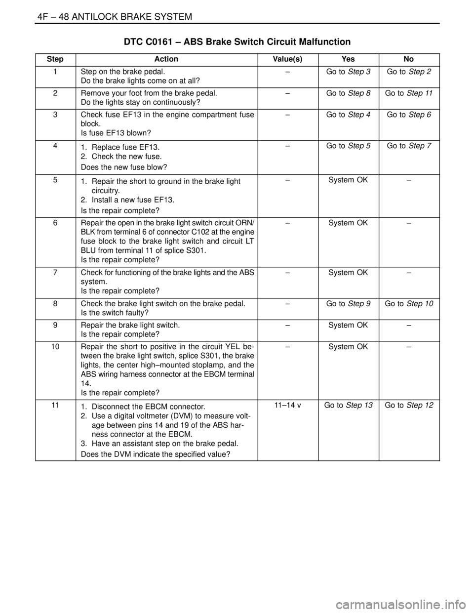
4F – 48IANTILOCK BRAKE SYSTEM
DAEWOO V–121 BL4
DTC C0161 – ABS Brake Switch Circuit Malfunction
StepActionValue(s)YesNo
1Step on the brake pedal.
Do the brake lights come on at all?–Go to Step 3Go to Step 2
2Remove your foot from the brake pedal.
Do the lights stay on continuously?–Go to Step 8Go to Step 11
3Check fuse EF13 in the engine compartment fuse
block.
Is fuse EF13 blown?–Go to Step 4Go to Step 6
41. Replace fuse EF13.
2. Check the new fuse.
Does the new fuse blow?–Go to Step 5Go to Step 7
51. Repair the short to ground in the brake light
circuitry.
2. Install a new fuse EF13.
Is the repair complete?–System OK–
6Repair the open in the brake light switch circuit ORN/
BLK from terminal 6 of connector C102 at the engine
fuse block to the brake light switch and circuit LT
BLU from terminal 11 of splice S301.
Is the repair complete?–System OK–
7Check for functioning of the brake lights and the ABS
system.
Is the repair complete?–System OK–
8Check the brake light switch on the brake pedal.
Is the switch faulty?–Go to Step 9Go to Step 10
9Repair the brake light switch.
Is the repair complete?–System OK–
10Repair the short to positive in the circuit YEL be-
tween the brake light switch, splice S301, the brake
lights, the center high–mounted stoplamp, and the
ABS wiring harness connector at the EBCM terminal
14.
Is the repair complete?–System OK–
111. Disconnect the EBCM connector.
2. Use a digital voltmeter (DVM) to measure volt-
age between pins 14 and 19 of the ABS har-
ness connector at the EBCM.
3. Have an assistant step on the brake pedal.
Does the DVM indicate the specified value?11–14 vGo to Step 13Go to Step 12
Page 1146 of 2643
ANTILOCK BRAKE SYSTEM 4F – 65
DAEWOO V–121 BL4
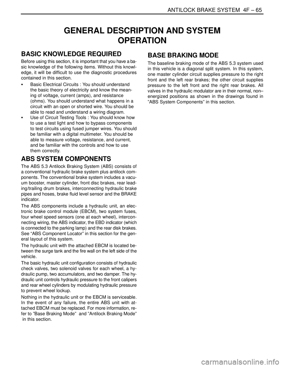
GENERAL DESCRIPTION AND SYSTEM
OPERATION
BASIC KNOWLEDGE REQUIRED
Before using this section, it is important that you have a ba-
sic knowledge of the following items. Without this knowl-
edge, it will be difficult to use the diagnostic procedures
contained in this section.
S Basic Electrical Circuits : You should understand
the basic theory of electricity and know the mean-
ing of voltage, current (amps), and resistance
(ohms). You should understand what happens in a
circuit with an open or shorted wire. You should be
able to read and understand a wiring diagram.
S Use of Circuit Testing Tools : You should know how
to use a test light and how to bypass components
to test circuits using fused jumper wires. You should
be familiar with a digital multimeter. You should be
able to measure voltage, resistance, and current,
and be familiar with the controls and how to use
them correctly.
ABS SYSTEM COMPONENTS
The ABS 5.3 Antilock Braking System (ABS) consists of
a conventional hydraulic brake system plus antilock com-
ponents. The conventional brake system includes a vacu-
um booster, master cylinder, front disc brakes, rear lead-
ing/trailing drum brakes, interconnecting hydraulic brake
pipes and hoses, brake fluid level sensor and the BRAKE
indicator.
The ABS components include a hydraulic unit, an elec-
tronic brake control module (EBCM), two system fuses,
four wheel speed sensors (one at each wheel), intercon-
necting wiring, the ABS indicator, the EBD indicator (which
is connected to the parking lamp) and the rear disk brakes.
See “ABS Component Locator” in this section for the gen-
eral layout of this system.
The hydraulic unit with the attached EBCM is located be-
tween the surge tank and the fire wall on the left side of the
vehicle.
The basic hydraulic unit configuration consists of hydraulic
check valves, two solenoid valves for each wheel, a hy-
draulic pump, two accumulators, and two damper. The hy-
draulic unit controls hydraulic pressure to the front calipers
and rear wheel cylinders by modulating hydraulic pressure
to prevent wheel lockup.
Nothing in the hydraulic unit or the EBCM is serviceable.
In the event of any failure, the entire ABS unit with at-
tached EBCM must be replaced. For more information, re-
fer to ”Base Braking Mode” and ”Antilock Braking Mode”
in this section.
BASE BRAKING MODE
The baseline braking mode of the ABS 5.3 system used
in this vehicle is a diagonal split system. In this system,
one master cylinder circuit supplies pressure to the right
front and the left rear brakes; the other circuit supplies
pressure to the left front and the right rear brakes. All
valves in the hydraulic modulator are in their normal, non–
energized positions as shown in the drawings found in
”ABS System Components” in this section.
Page 1152 of 2643
ANTILOCK BRAKE SYSTEM 4F – 71
DAEWOO V–121 BL4
TIRES AND ABS/EBD
Replacement Tires
Tire size is important for proper performance of the ABS
system. Replacement tires should be the same size, load
range, and construction as the original tires. Replace tires
in axle sets and only with tires of the same tire perfor-
mance criteria (TPC) specification number. Use of any
other size or type may seriously affect the ABS operation.
TIRES AND ABS/EBD
Notice : There is no serviceable or removable EEPROM.
The EBCM must be replaced as an assembly.
The EBCM is attached to the hydraulic unit in the engine
compartment. The controlling element of ABS 5.3 is a mi-
croprocessor–based EBCM. Inputs to the system include
the four wheel speed sensors, the stoplamp switch, the
ignition switch, and the unswitched battery voltage. There
is an output to a bi–directional serial data link, located in
pin K of Data Link Connector (DLC) for service diagnostic
tools and assembly plant testing.
The EBCM monitors the speed of each wheel. If any wheel
begins to approach lockup and the brake switch is closed
(brake pedal depressed), the EBCM controls the sole-
noids to reduce brake pressure to the wheel approaching
lockup. Once the wheel regains traction, brake pressure
is increased until the wheel again begins to approach lock-
up. This cycle repeats until either the vehicle comes to a
stop, the brake pedal is released, or no wheels approach
lockup.
Additionally, the EBCM monitors itself, each input (except
the serial data link), and each output for proper operation.
If it detects any system malfunction, the EBCM will store
a DTC in nonvolatile memory (EEPROM) (DTCs will not
disappear if the battery is disconnected). Refer to ”Self
Diagnostics” in this section for more detailed information.
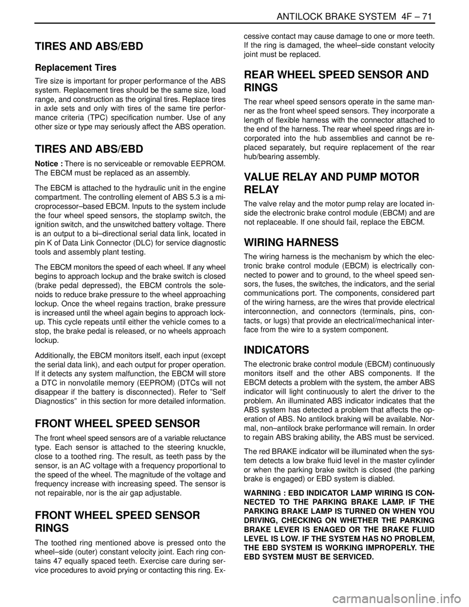
FRONT WHEEL SPEED SENSOR
The front wheel speed sensors are of a variable reluctance
type. Each sensor is attached to the steering knuckle,
close to a toothed ring. The result, as teeth pass by the
sensor, is an AC voltage with a frequency proportional to
the speed of the wheel. The magnitude of the voltage and
frequency increase with increasing speed. The sensor is
not repairable, nor is the air gap adjustable.
FRONT WHEEL SPEED SENSOR
RINGS
The toothed ring mentioned above is pressed onto the
wheel–side (outer) constant velocity joint. Each ring con-
tains 47 equally spaced teeth. Exercise care during ser-
vice procedures to avoid prying or contacting this ring. Ex-cessive contact may cause damage to one or more teeth.
If the ring is damaged, the wheel–side constant velocity
joint must be replaced.
REAR WHEEL SPEED SENSOR AND
RINGS
The rear wheel speed sensors operate in the same man-
ner as the front wheel speed sensors. They incorporate a
length of flexible harness with the connector attached to
the end of the harness. The rear wheel speed rings are in-
corporated into the hub assemblies and cannot be re-
placed separately, but require replacement of the rear
hub/bearing assembly.
VALUE RELAY AND PUMP MOTOR
RELAY
The valve relay and the motor pump relay are located in-
side the electronic brake control module (EBCM) and are
not replaceable. If one should fail, replace the EBCM.
WIRING HARNESS
The wiring harness is the mechanism by which the elec-
tronic brake control module (EBCM) is electrically con-
nected to power and to ground, to the wheel speed sen-
sors, the fuses, the switches, the indicators, and the serial
communications port. The components, considered part
of the wiring harness, are the wires that provide electrical
interconnection, and connectors (terminals, pins, con-
tacts, or lugs) that provide an electrical/mechanical inter-
face from the wire to a system component.
INDICATORS
The electronic brake control module (EBCM) continuously
monitors itself and the other ABS components. If the
EBCM detects a problem with the system, the amber ABS
indicator will light continuously to alert the driver to the
problem. An illuminated ABS indicator indicates that the
ABS system has detected a problem that affects the op-
eration of ABS. No antilock braking will be available. Nor-
mal, non–antilock brake performance will remain. In order
to regain ABS braking ability, the ABS must be serviced.
The red BRAKE indicator will be illuminated when the sys-
tem detects a low brake fluid level in the master cylinder
or when the parking brake switch is closed (the parking
brake is engaged) or EBD system is diabled.
WARNING : EBD INDICATOR LAMP WIRING IS CON-
NECTED TO THE PARKING BRAKE LAMP. IF THE
PARKING BRAKE LAMP IS TURNED ON WHEN YOU
DRIVING, CHECKING ON WHETHER THE PARKING
BRAKE LEVER IS ENAGED OR THE BRAKE FLUID
LEVEL IS LOW. IF THE SYSTEM HAS NO PROBLEM,
THE EBD SYSTEM IS WORKING IMPROPERLY. THE
EBD SYSTEM MUST BE SERVICED.
Page 1155 of 2643
PARKING BRAKE 4G – 3
DAEWOO V–121 BL4
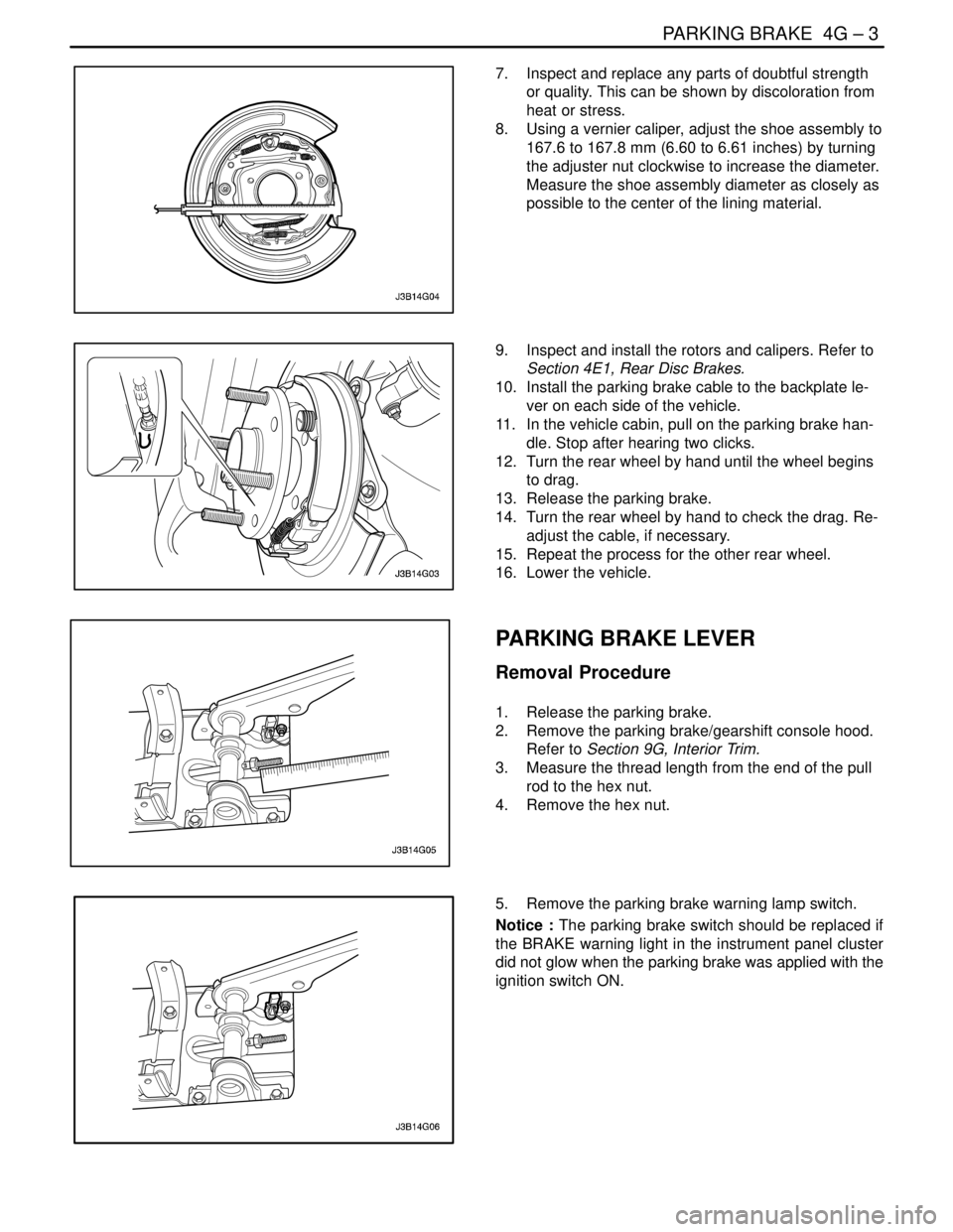
7. Inspect and replace any parts of doubtful strength
or quality. This can be shown by discoloration from
heat or stress.
8. Using a vernier caliper, adjust the shoe assembly to
167.6 to 167.8 mm (6.60 to 6.61 inches) by turning
the adjuster nut clockwise to increase the diameter.
Measure the shoe assembly diameter as closely as
possible to the center of the lining material.
9. Inspect and install the rotors and calipers. Refer to
Section 4E1, Rear Disc Brakes.
10. Install the parking brake cable to the backplate le-
ver on each side of the vehicle.
11. In the vehicle cabin, pull on the parking brake han-
dle. Stop after hearing two clicks.
12. Turn the rear wheel by hand until the wheel begins
to drag.
13. Release the parking brake.
14. Turn the rear wheel by hand to check the drag. Re-
adjust the cable, if necessary.
15. Repeat the process for the other rear wheel.
16. Lower the vehicle.
PARKING BRAKE LEVER
Removal Procedure
1. Release the parking brake.
2. Remove the parking brake/gearshift console hood.
Refer to Section 9G, Interior Trim.
3. Measure the thread length from the end of the pull
rod to the hex nut.
4. Remove the hex nut.
5. Remove the parking brake warning lamp switch.
Notice : The parking brake switch should be replaced if
the BRAKE warning light in the instrument panel cluster
did not glow when the parking brake was applied with the
ignition switch ON.
Page 1161 of 2643

PARKING BRAKE 4G – 9
DAEWOO V–121 BL4
GENERAL DESCRIPTION
AND SYSTEM OPERATION
PARKING BRAKE
This braking system uses a BRAKE warning light located
in the instrument panel cluster. When the ignition switch
is in the START position, the BRAKE warning light shouldglow and go OFF when the the ignition switch returns to
the RUN position. Whenever the parking brake is applied
and the ignition switch is ON, the BRAKE warning light
should glow.
When the brake is firmly applied, the parking brake should
hold the vehicle with ample pedal travel remaining. Check
for frayed cables, rust, etc. or any condition that many in-
hibit present (or future) free movement of the parking
brake lever assembly.
Page 1395 of 2643
5A1 – 46IZF 4 HP 16 AUTOMATIC TRANSAXLE
DAEWOO V–121 BL4
sible, drive the vehicle for a few kilometers (N–D,
N–R, shift until two gear). This will allow the trans-
axle to be within the correct temperature range.
Transaxle fluid level should be checked at tempera-
ture 20 to 45°C (68 to 113°F).
CAUTION : Removal of the fluid filler plug when the
transaxle fluid is hot may cause injury if fluid drains
from the filler hole.
2. Switch off accessories, especially air conditioner,
heater.
3. With the brake pedal pressed, move the gear shift
control lever through the gear ranges, pausing a
few seconds in each range. Return the gearshift
lever to P(Park). Turn the engine OFF.
4. Park the vehicle on a hoist, inspection pit or similar
raised level surface. The vehicle must be level to
obtain a correct fluid level measurement.
5. Place a fluid container below the fluid filler plug.
6. Clean all dirt from around the fluid filler plug.
Remove the fluid filler plug. Clean the filler plug and
check that there is no damage to the ”O” ring.
S If fluid drains through the filler hole the transaxle
may have been overfilled. When the fluid stops
draining the fluid level is correct. Install the fluid
filler plug and tighten it to 45NSm(34 lb–ft).
S If fluid does not drain through the filler hole, the
transaxle fluid level may be low. Lower the ve-
hicle, and start the vehicle in P(Park) with the
parking brake and the brake applied. With the
engine idling, move the gear shift lever through
the gear ranges, pausing a few seconds in each
range and adding the fluid until gear application
is felt. Return the gear shift lever to P(Park).
Turn the engine OFF and raise the vehicle.
Check if the fluid level is aligned with the bottom
of the filler hole. If not, add a small quantity of
fluid to the correct level. Install the fluid filler
plug and tighten it to 45NSm(34 lb–ft).
7. When the fluid level checking procedure is com-
pleted, wipe any fluid around the filler plug with a
rag or shop towel.
Fluid Level Set After Service
1. Depending on the service procedure performed,
add the following amounts of fluid through the filler
plug hole prior to adjusting the fluid level:
Oil pan removal – 4 liters (4.23 quarts)
Converter removal – 2 liters ( 2.11 quarts)
Overhaul – 6.9liters (7.3 quarts)
Oil drain plug removal – 4 liters (4.23 quarts)
2. Follow steps 1 through 4 of the Fluid Level Diagno-
sis Procedure.
3. Clean all dirt from around the fluid filler plug.
Remove the fluid filler plug. Clean the filler plug and
check that there is no damage to the ”O” ring.
4. Lower the vehicle with the filler plug still removed
and start the vehicle in P(Park) with the parking
brake and the brake applied. With the engine idling,move the gear shift lever through the gear ranges,
pausing a few seconds in each range and adding
the fluid until gear application is felt. Then add an
additional 0.5 liters of fluid. Return the gear shift
lever to P(Park). Turn the engine OFF and raise the
vehicle. Install the fluid filler plug and tighten it to
45NSm (34 lb–ft).
5. Drive the vehicle at 2.2 miles(3.5km) to 2.8
miles(4.5 km) with light throttle so that the engine
does not exceed 2500 rpm. This should result in
the transaxle temperature being in the range 20 to
45°C (68 to 11°F). With the brake applied, move
the shift lever through the gear ranges, pausing a
few seconds in each range at the engine idling.
6. Return the gear shift lever to P(Park). Turn the en-
gine OFF and raise the vehicle on the hoist, if appli-
cable, ensuring the vehicle is level. When the three
minutes passed after the engine stopped, remove
the filler plug. Check if the fluid level is aligned with
the bottom of the filler hole. If not, add a small
quantity of fluid to the correct level. Install the fluid
filler plug and tighten it to 45NSm (34 lb–ft).
7. Wipe any fluid around the filler plug with a rag or
shop towel.
Fluid Leak Diagnosis and Repair
The cause of most external leaks can generally be Lo-
cated and repaired with the transaxle in the vehicle.
Methods for Locating Leaks
General Method
1. Verify that the leak is transaxle fluid.
2. Thoroughly clean the suspected leak area.
3. Drive the vehicle for approximately 25 km (15
miles) or until the transaxle reaches normal operat-
ing temperature (88°C, 190°F).
4. Park the vehicle over clean paper or cardboard.
5. Turn the engine OFF and look for fluid spots on the
paper.
6. Make the necessary repairs to correct the leak.
Powder Method
1. Thoroughly clean the suspected leak area.
2. Apply an aerosol type powder (foot powder) to the
suspected leak area.
3. Drive the vehicle for approximately 25 km (15
miles) or until the transaxle reaches normal operat-
ing temperature (88°C, 190°F).
4. Turn the engine OFF.
5. Inspect the suspected leak area and trace the leak
path through the powder to find the source of the
leak.
6. Make the necessary repairs.
Dye and Black Light Method
1. Add dye to the transaxle though the transaxle fluid
filler plug. Follow the manufacturer’s recommenda-
tion for the amount of dye to be used.
2. Use the black light to find the fluid leak.
3. Make the necessary repairs.
Page 1396 of 2643
ZF 4 HP 16 AUTOMATIC TRANSAXLE 5A1 – 47
DAEWOO V–121 BL4
Repairing the Fluid Leak
Once the leak point is found the source of the leak must
be determined. The following list describes the potential
causes for the leak:
S Fasteners are not torqued to specification.
S Fastener threads and fastener holes are dirty or
corroded.
S Gaskets, seals or sleeves are misarranged, dam-
aged or worn.
S Damaged, warped or scratched seal bore or gasket
surface.
S Loose or worn bearing causing excess seal or
sleeve wears.
S Case or component porosity.
S Fluid level is too high.
S Plugged vent or damaged vent tube.
S Water or coolant in fluid.
S Fluid drain back holes plugged.
ELECTRICAL/GARAGE SHIFT TEST
This preliminary test should be performed before a hoist
or road test to make sure electronic control inputs is con-
nected and operating. If the inputs are not checked before
operating the transaxle, a simple electrical condition could
be misdiagnosed as a major transaxle condition.
A scan tool provides valuable information and must be
used on the automatic transaxle for accurate diagnosis.
1. Move gear selector to P (Park) and set the parking
brake.
2. Connect scan tool to Data Link Connector (DLC)
terminal.
3. Start engine.
4. Turn the scan tool ON.
5. Verify that the appropriate signals are present.
These signals may include:
S ENGINE SPEED
S VEHICLE SPEED
S THROTTLE POSITION
S TRANSAXLE GEAR STATE
S GEAR SHIFT LEVER POSITION
S TRANSAXLE FLUID TEMPERATURE
S CLOSED THROTTLE POSITION LEARN
S OPEN THROTTLE POSITION LEARNT
S CLOSED ACCEL. PEDAL POSITION LEARNT
S OPEN ACCEL. PEDAL POSITION LEARNT
S A/C COMPRESSOR STATUS
S MODE SWITCH
S THROTTLE POSITION VOLTAGE
S GEAR SHIFT LEVER POSITION VOLTAGE
S TRANS. FLUID TEMPERATURE VOLTAGE
S A/C SWITCH
S MODE SWITCH VOLTAGE
S BATTERY VOLTAGE
6. Monitor the A/C COMPRESSOR STATUS signal
while pushing the A/C switch.S The A/C COMPRESSOR STATUS should come
ON when the A/C switch is pressed, and turns
OFF when the A/C switch is repushed.
7. Monitor the GEAR SHIFT LEVER POSITION signal
and move the gear shift control lever through all the
ranges.
S Verify that the GEAR SHIFT LEVER POSITION
value matches the gear range indicated on the
instrument panel or console.
S Gear selections should be immediate and not
harsh.
8. Move gear shift control lever to neutral and monitor
the THROTTLE POSITION signal while increasing
and decreasing engine speed with the accelerator
pedal.
S THROTTLE POSITION should increase with
engine speed.
ROAD TEST PROCEDURE
S Perform the road test using a scan tool.
S This test should be performed when traffic and road
conditions permit.
S Observe all traffic regulations.
The TCM calculates upshift points based primarily on two
inputs : throttle angle and vehicle speed. When the TCM
wants a shift to occur, an electrical signal is sent to the shift
solenoids which in turn moves the valves to perform the
upshift.
The shift speed charts reference throttle angle instead of
”min throttle” or ”wot” to make shift speed measurement
more uniform and accurate. A scan tool should be used to
monitor throttle angle. Some scan tools have been pro-
grammed to record shift point information. Check the
introduction manual to see if this test is available.
Upshift Procedure
With gear selector in drive(D)
1. Look at the shift speed chart contained in this sec-
tion and choose a percent throttle angle of 10 or
25%.
2. Set up the scan tool to monitor throttle angle and
vehicle speed.
3. Accelerate to the chosen throttle angle and hold the
throttle steady.
4. As the transaxle upshifts, note the shift speed and
commanded gear changes for :
S Second gear.
S Third gear.
S Fourth gear.
Important : Shift speeds may vary due to slight hydraulic
delays responding to electronic controls. A change from
the original equipment tire size affects shift speeds.
Note when TCC applies. This should occur in fourth gear.
If the apply is not noticed by an rpm drop, refer to the
”Lock–up Clutch Diagnosis” information contained in this
section.
Page 1397 of 2643
5A1 – 48IZF 4 HP 16 AUTOMATIC TRANSAXLE
DAEWOO V–121 BL4
The Lock up clutch should not apply unless the transaxle
has reached a minimum operating temperature of 8°C
(46°F) TRANS TEMP AND engine coolant temp of 50°C
(122°F).
5. Repeat steps 1–4 using several different throttle
angles.
Part Throttle Detent Downshift
At vehicle steeds of 55 to 65km/h (34 to 40mph) in Fourth
gear, quickly increase throttle angle to greater than 50%.
Verify that :
S TCC apply.
S Transaxle downshift to 3rd gear.
S Solenoid 1 turns ON to OFF.
S Solenoid 2 turns OFF.
Full Throttle Detent Downshift
At vehicle speeds of 55 to 65km/h (34 to 40mph)in Fourth
gear, quickly increase throttle angle to its maximum posi-
tion (100%)
Verify that :
S TCC release.
S Transaxle downshift to Second gear immediately.
S Solenoid 1 turns ON to OFF
S Solenoid 2 turns OFF.
Manual Downshifts
1. At vehicle speeds of 60km/h (40mph)in Fourth
gear, release accelerator pedal while moving gear
selector to Manual Third (3). Observe that :
S Transaxle downshift to Third gear immediately.
S Engine slows vehicle down.
2. Move gear selector back to overdrive(D) and accel-
erate to 31mph (50km/h). Release the accelerator
pedal and move the gear selector to Manual
First(1) and observe that :
S Transaxle downshift to second gear immediate-
ly.
S Engine slows vehicle down
Notice : A Manual First––Third Gear Ratio will occur at
high speeds as an upshift safety feature. Do not attempt
to perform this shift.
Coasting Downshifts
1. With the gear selector in Overdrive(D), accelerate
to Fourth gear with TCC applied.
2. Release the accelerator pedal and lightly apply the
brakes, and observe that :
S TCC release.
S Down shifts occur at speeds shown ON the shift
speed chart.
Manual Gear Range Selection
Upshifts in the manual gear ranges are controlled by the
shift solenoids. Perform the following tests by accelerating
at 25 percent TP sensor increments.
Manual Third (3)
S With vehicle stopped, move the gear selector to
Manual third(3) and accelerate to observe :
– 1–2 shift.
– 2–3 shift.
Manual Second (2)
S With vehicle stopped, move the gear selector to
Manual second(2) and accelerate to observe :
– 1–2 shift.
S Accelerate to 40km/h(25mph) and observe :
– 2–3 shift does not occur
– TCC does not apply
Manual First (1)
S With vehicle stopped, move gear selector to Manu-
al First(1). Accelerate to 30km/h(19mph) and ob-
serve :
– No upshifts occur
Reverse (R)
S With vehicle stopped, move gear selector to R(Re-
verse) and observe :
– Solenoid 1 is OFF
– Solenoid 2 is OFF
Use a scan tool to see if any transaxle trouble codes have
been set. Refer to ”Diagnostic Trouble Codes”in this sec-
tion and repair the vehicle as directed. After repairing the
vehicle, perform the hoist test and verify that the code has
not set again.
If the transaxle is not performing well and no trouble codes
have been set, there may be an intermittent condition.
Check all electrical connections for damage or a loose fit.
You also have to perform a snapshot test which can help
catch an intermittent condition that dose not occur long
enough to set a code.
You may want to read ”Electronic Component Diagnosis”
in this section to become familiar with transaxle conditions
caused by transaxle electrical malfunction.
If no trouble codes have been set and the condition is sus-
pected to be hydraulic, take the vehicle on a road test.
TORQUE CONVERTER LOCK–UP
CLUTCH(TCC) DIAGNOSIS
To properly diagnosis the lock–up clutch(TCC) system,
perform all electrical testing first and then the hydraulic
testing.
The TCC is applied by fluid pressure which is controlled by
a solenoid Located inside the valve body. The solenoid is
energized by completing an electrical circuit through a
combination of switches and sensors.
Page 1398 of 2643
ZF 4 HP 16 AUTOMATIC TRANSAXLE 5A1 – 49
DAEWOO V–121 BL4
Functional Check Procedure
Inspect
1. Install a tachometer or scan tool.
2. Operate the vehicle unit proper operating tempera-
ture is reached.
3. Drive the vehicle at 80 to 88km/h (50 to 55 mph)
with light throttle(road load).
4. Maintaining throttle position, lightly touch the brake
pedal and check for release of the TCC and a slight
increase in engine speed(rpm).
5. Release the brake slowly accelerate and check for
a reapply of the Lock up clutch and a slight de-
crease in engine speed(rpm).
Torque Converter Evaluation
Torque Converter Stator
The torque converter stator roller clutch can have one of
two different type malfunctions :
A. Stator assembly freewheels in both directions.
B. Stator assembly remains Locked up at all times.
Condition A – Poor Acceleration Low
Speed
The car tends to have poor acceleration from a stand still.
At speeds above 50 to 55km/h(30 to 35mph), the car may
act normal. If poor acceleration is noted, it should first be
determined that the exhaust system is not blocked, and
the transaxle is in 1st(First) gear when starting out.
If the engine freely accelerates to high rpm in N(Neutral),
it can be assumed that the engine and exhaust system are
normal. Checking for poor performance in ”Drive” and ”Re-
verse” will help determine if the stator is freewheeling at all
times.
Condition B – Poor Acceleration High
Speed
Engine rpm and car speed limited or restricted at high
speeds. Performance when accelerating from a standstill
is normal. Engine may overheat. Visual examination of the
converter may reveal a blue color from overheating.
If the converter has been removed, the stator roller clutch
can be checked by inserting two fingers into the splined in-
ner race of the roller clutch and trying to turn freely clock-
wise, but not turn or be very difficult to turn counter clock-
wise.
Noise
Torque converter whine is usually noticed when the ve-
hicle is stopped and the transaxle is in ”Drive” or ”Re-
verse”. The noise will increase when engine rpm is in-
creased. The noise will stop when the vehicle is moving or
when the torque converter clutch is applied because both
halves of the converter are turning at the same speed.
Perform a stall test to make sure the noise is actually com-
ing from the converter :1. Place foot on brake.
2. Put gear selector in ”Drive”.
3. Depress accelerator to approximately 1200rpm for
no more than six seconds.
Notice : If the accelerator is depressed for more than six
seconds, damage to the transaxle may occur.
A torque converter noise will increase under this load.
Important : This noise should not be confused with pump
whine noise which is usually noticeable in P (Park), N
(Neutral) and all other gear ranges. Pump whine will vary
with pressure ranges.
The torque converter should be replaced under any of the
following conditions:
S External leaks in the hub weld area.
S Converter hub is scored or damaged.
S Converter pilot is broken, damaged or fits poorly
into crankshaft.
S Steel particles are found after flushing the cooler
and cooler lines.
S Pump is damaged or steel particles are found in the
converter.
S Vehicle has TCC shudder and/or no TCC apply.
Replace only after all hydraulic and electrical diag-
noses have been made.(Lock up clutch material
may be glazed.)
S Converter has an imbalance which cannot be cor–
rected. (Refer To Converter Vibration Test Proce-
dure.)
S Converter is contaminated with engine coolant con-
taining antifreeze.
S Internal failure of stator roller clutch.
S Excess end play.
S Heavy clutch debris due to overheating (blue con-
verter).
S Steel particles or clutch lining material found in fluid
filter or on magnet when no internal parts in unit are
worn or damaged(indicates that lining material
came from converter).
The torque converter should not be replace if :
S The oil has an odor, is discolored, and there is no
evidence of metal or clutch facing particles.
S The threads in one or more of the converter bolt
holes are damaged.
–correct with thread insert.
S Transaxle failure did not display evidence of dam-
age or worn internal parts, steel particles or clutch
plate lining material in unit and inside the fluid filter.
S Vehicle has been exposed to high mileage(only).
The exception may be where the Lock up clutch
damper plate lining has seen excess wear by ve-
hicles operated in heavy and/or constant traffic,
such as taxi, delivery or police use.
Lock–Up Clutch Shudder Diagnosis
The key to diagnosing lock–up clutch(TCC) shudder is to
note when it happens and under what conditions.
Page 1410 of 2643
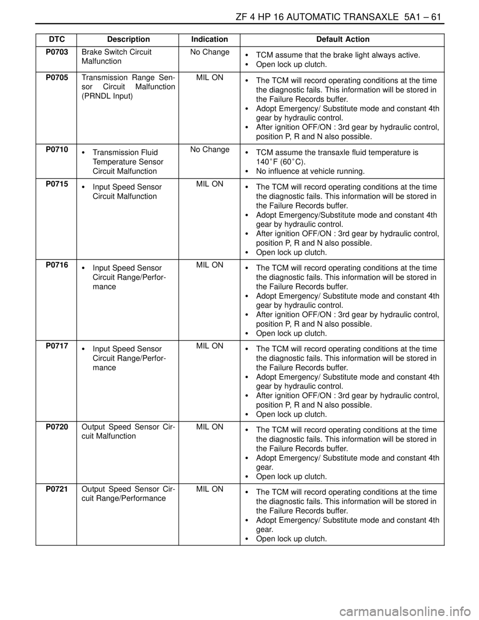
ZF 4 HP 16 AUTOMATIC TRANSAXLE 5A1 – 61
DAEWOO V–121 BL4
DTCDefault Action Indication Description
P0703Brake Switch Circuit
MalfunctionNo ChangeS TCM assume that the brake light always active.
S Open lock up clutch.
P0705Transmission Range Sen-
sor Circuit Malfunction
(PRNDL Input)MIL ONS The TCM will record operating conditions at the time
the diagnostic fails. This information will be stored in
the Failure Records buffer.
S Adopt Emergency/ Substitute mode and constant 4th
gear by hydraulic control.
S After ignition OFF/ON : 3rd gear by hydraulic control,
position P, R and N also possible.
P0710S Transmission Fluid
Temperature Sensor
Circuit MalfunctionNo ChangeS TCM assume the transaxle fluid temperature is
140°F (60°C).
S No influence at vehicle running.
P0715S Input Speed Sensor
Circuit MalfunctionMIL ONS The TCM will record operating conditions at the time
the diagnostic fails. This information will be stored in
the Failure Records buffer.
S Adopt Emergency/Substitute mode and constant 4th
gear by hydraulic control.
S After ignition OFF/ON : 3rd gear by hydraulic control,
position P, R and N also possible.
S Open lock up clutch.
P0716S Input Speed Sensor
Circuit Range/Perfor-
manceMIL ONS The TCM will record operating conditions at the time
the diagnostic fails. This information will be stored in
the Failure Records buffer.
S Adopt Emergency/ Substitute mode and constant 4th
gear by hydraulic control.
S After ignition OFF/ON : 3rd gear by hydraulic control,
position P, R and N also possible.
S Open lock up clutch.
P0717S Input Speed Sensor
Circuit Range/Perfor-
manceMIL ONS The TCM will record operating conditions at the time
the diagnostic fails. This information will be stored in
the Failure Records buffer.
S Adopt Emergency/ Substitute mode and constant 4th
gear by hydraulic control.
S After ignition OFF/ON : 3rd gear by hydraulic control,
position P, R and N also possible.
S Open lock up clutch.
P0720Output Speed Sensor Cir-
cuit MalfunctionMIL ONS The TCM will record operating conditions at the time
the diagnostic fails. This information will be stored in
the Failure Records buffer.
S Adopt Emergency/ Substitute mode and constant 4th
gear.
S Open lock up clutch.
P0721Output Speed Sensor Cir-
cuit Range/PerformanceMIL ONS The TCM will record operating conditions at the time
the diagnostic fails. This information will be stored in
the Failure Records buffer.
S Adopt Emergency/ Substitute mode and constant 4th
gear.
S Open lock up clutch.