heating DAEWOO LACETTI 2004 Service Repair Manual
[x] Cancel search | Manufacturer: DAEWOO, Model Year: 2004, Model line: LACETTI, Model: DAEWOO LACETTI 2004Pages: 2643, PDF Size: 80.54 MB
Page 5 of 2643

v
TABLE OF CONTENTS
Section 0B General Information
Section 1 Engine
Section 1A General Engine Information
Section 1C1 1.4L/1.6L DOHC Engine Mechanical
Section 1C2 1.8L DOHC Engine Mechanical
Section 1D Engine Cooling
Section 1E Engine Electrical
Section 1F Engine Controls
Section 1G Engine Exhaust
Section 2 Suspension
Section 2A Suspension Diagnosis
Section 2B Wheel Alignment
Section 2C Front Suspension
Section 2D Rear Suspension
Section 2E Tires and Wheels
Section 3 Driveline/Axle
Section 3A Automatic Transaxle Drive Axle
Section 3B Manual Transaxle Drive Axle
Section 4 Brakes
Section 4A Hydraulic Brakes
Section 4B Master Cylinder
Section 4C Power Booster
Section 4D Front Disc Brakes
Section 4E1 Rear Disc Brakes
Section 4E2 Rear Drum Brakes
Section 4F Antilock Brake System
Section 4G Parking Brake
Section 5 Transmission/Transaxle
Section 5A1 ZF 4HP16 Automatic Transaxle
Section 5A2 AISIN Automatic Transaxle
Section 5B Five-Speed Manual Transaxle
Section 5C Clutch
Section 6 Steering
Section 6A Power Steering System
Section 6B Power Steering PumpSection 6C Power Steering Gear
Section 6E Steering Wheel and Column
Section 7 Heating, Ventilation, and Air
Conditioning (HVAC)
Section 7A Heating and Ventilation System
Section 7B Manual Control Heating, Ventilation,
and Air Conditioning System
Section 7D Automatic Temperature Control HVAC
Section 8 Restraints
Section 8A Seat Belts
Section 8B Supplemental Inflatable Restraints
(SIR)
Section 9 Body and Accessories
Section 9A Body Wiring System
Section 9B Lighting Systems
Section 9C Horns
Section 9D Wipers/Washer Systems
Section 9E Instrumentation/Driver Information
Section 9F Audio Systems
Section 9G Interior Trim
Section 9H Seats
Section 9I Waterleaks
Section 9J Windnoise
Section 9K Squeaks and Rattles
Section 9L Glass and Mirrors
Section 9M Exterior Trim
Section 9N Frame and Underbody
Section 9O Bumpers and Fascias
Section 9P Doors
Section 9Q Roof
Section 9R Body Front End
Section 9S Body Rear End
Section 9T1 Remote Keyless Entry and Anti–Theft
System
Section 9T2 Immobilizer Anti–Theft System
Page 19 of 2643

0B – 12IGENERAL INFORMATION
DAEWOO V–121 BL4
OWNER INSPECTIONS AND SERVICES
WHLE OPERATING THE VEHICLE
Horn Operation
Blow the horn occasionally tomake sure it works. Check
all the button locations.
Brake System Operation
Be alert for abnormal sounds, increased brake pedal trav-
el or repeated pulling to one side when braking. Also, if the
brake warning light goes on, or flashes, something may be
wrong with part of the brake system.
Exhaust System Operation
Be alert to any changes in the sound of the system or the
smell of the fumes. These are signs that the system may
be leaking or overheating. Have the system inspected and
repaired immediately.
Tires,Wheels and Alignment Operation
Be alert to any vibration of the steering wheel or the seats
at normal highway speeds. This may mean a wheel needs
to be balanced. Also, a pull right or left on a straight, level
road may show the need for a tire pressure adjustment or
a wheel alignment.
Steering System Operation
Be alert to changes in the steering action. An inspection
is needed when the steering wheel is hard to turn or has
too much free play, or if unusual sounds are noticed when
turning or parking.
Headlight Aim
Take note of the light pattern occasionally. Adjust the
headlights if the beams seem improperly aimed.
AT EACH FUEL FILL
A fluid loss in any (except windshield washer) system may
indicate a problem. Have the system inspected and re-
paired immediately.
Engine Oil Level
Check the oil level and add oil if necessary. The best time
to check the engine oil level is when the oil is warm.
1. After stopping the engine, wait a few minutes for
the oil to drain back to the oil pan.
2. Pull out the oil level indicator (dip stick).
3. Wipe it clean, and push the oil level indicator back
down all the way.
4. Pull out the oil level indicator and look at the oil lev-
el on it.
5. Add oil, if needed, to keep the oil level above the
MIN line and within the area labeled ”Operating
Range.” Avoid overfilling the engine, since this may
cause engine damage.
6. Push the indicator all the way back down into the
engine after taking the reading.If you check the oil level when the oil is cold, do not run the
engine first. The cold oil will not drain back to the pan fast
enough to give a true oil level reading.
Engine Coolant Level and Condition
Check the coolant level in the coolant reservoir tank and
add coolant if necessary. Inspect the coolant. Replace
dirty or rusty coolant.
Windshield Washer Fluid Level
Check the washer fluid level in the reservoir. Add fluid if
necessary.
AT LEAST MONTHLY
Tire And Wheel Inspection and Pressure
Check
Check the tires for abnormal wear or damage. Also check
for damaged wheels. Check the tire pressure when the
tires are cold (check the spare also, unless it is a stow-
away). Maintain the recommended pressures that are on
the tire placard that is in the glove box.
Light Operation
Check the operation of the license plate light, the head-
lights (including the high beams), the parking lights, the
fog lights, the taillight, the brake lights, the turn signals, the
backup lights and the hazard warning flasher.
Fluid Leak Check
Periodically inspect the surface beneath the vehicle for
water, oil, fuel or other fluids, after the vehicle has been
parked for a while. Water dripping from the air conditioning
system after use is normal. If you notice fuel leaks or
fumes, find the cause and correct it at once.
AT LEAST TWICE A YEAR
Power Steering System Reservoir Level
Check the power steering fluid level. Keep the power
steering fluid at the proper level. Refer to Section 6A, Pow-
er Steering System.
Brake Master Cylinder Reservoir Level
Check the fluid and keep it at the proper level. A low fluid
level can indicate worn disc brake pads which may need
to be serviced. Check the breather hole in the reservoir
cover to be free from dirt and check for an open passage.
Clutch Pedal Free Travel
Check clutch pedal free travel and adjust as necessary.
Measure the distance from the center of the clutch pedal
to the outer edge of the steering wheel with the clutch ped-
al not depressed. Then measure the distance from the
center of the clutch pedal to the outer edge of the steering
wheel with the clutch pedal fully depressed. The difference
between the two values must be greater than 130 mm
(5.19 inches).
Weather–Strip Lubrication
Apply a thin film silicone grease using a clean cloth.
Page 92 of 2643
1.4L/1.6L DOHC ENGINE MECHANICAL 1C1 – 49
DAEWOO V–121 BL4
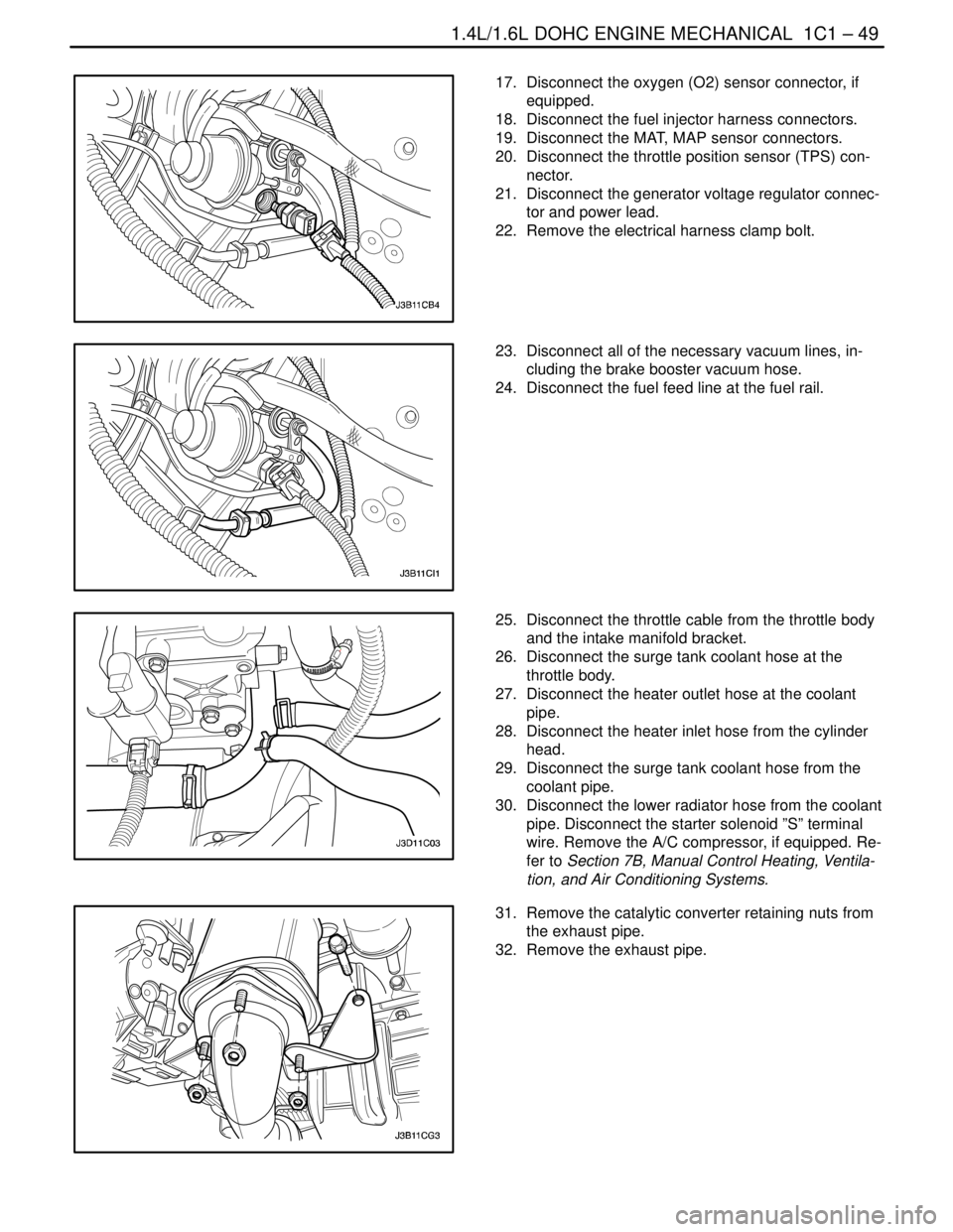
17. Disconnect the oxygen (O2) sensor connector, if
equipped.
18. Disconnect the fuel injector harness connectors.
19. Disconnect the MAT, MAP sensor connectors.
20. Disconnect the throttle position sensor (TPS) con-
nector.
21. Disconnect the generator voltage regulator connec-
tor and power lead.
22. Remove the electrical harness clamp bolt.
23. Disconnect all of the necessary vacuum lines, in-
cluding the brake booster vacuum hose.
24. Disconnect the fuel feed line at the fuel rail.
25. Disconnect the throttle cable from the throttle body
and the intake manifold bracket.
26. Disconnect the surge tank coolant hose at the
throttle body.
27. Disconnect the heater outlet hose at the coolant
pipe.
28. Disconnect the heater inlet hose from the cylinder
head.
29. Disconnect the surge tank coolant hose from the
coolant pipe.
30. Disconnect the lower radiator hose from the coolant
pipe. Disconnect the starter solenoid ”S” terminal
wire. Remove the A/C compressor, if equipped. Re-
fer to Section 7B, Manual Control Heating, Ventila-
tion, and Air Conditioning Systems.
31. Remove the catalytic converter retaining nuts from
the exhaust pipe.
32. Remove the exhaust pipe.
Page 95 of 2643
1C1 – 52I1.4L/1.6L DOHC ENGINE MECHANICAL
DAEWOO V–121 BL4
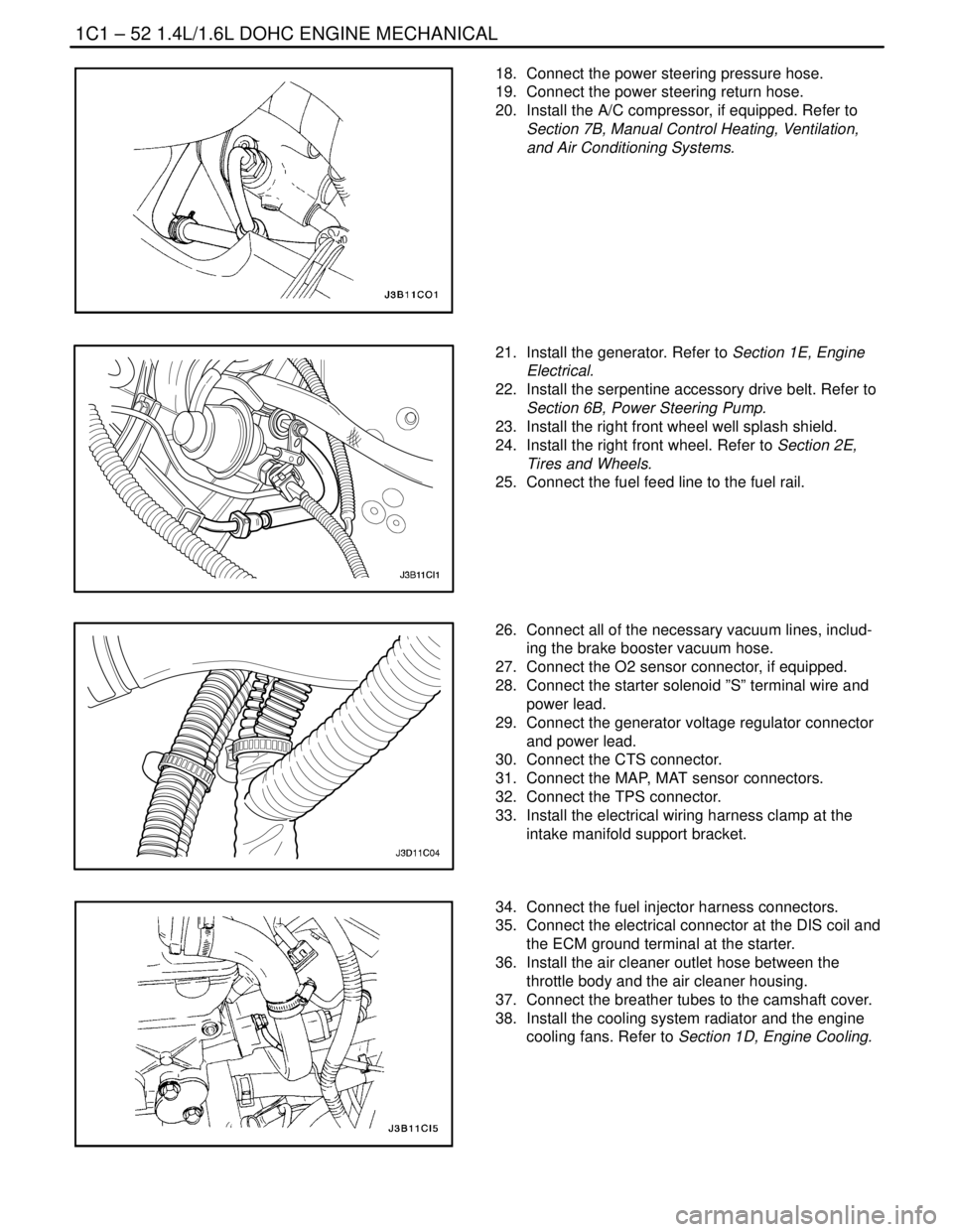
18. Connect the power steering pressure hose.
19. Connect the power steering return hose.
20. Install the A/C compressor, if equipped. Refer to
Section 7B, Manual Control Heating, Ventilation,
and Air Conditioning Systems.
21. Install the generator. Refer to Section 1E, Engine
Electrical.
22. Install the serpentine accessory drive belt. Refer to
Section 6B, Power Steering Pump.
23. Install the right front wheel well splash shield.
24. Install the right front wheel. Refer to Section 2E,
Tires and Wheels.
25. Connect the fuel feed line to the fuel rail.
26. Connect all of the necessary vacuum lines, includ-
ing the brake booster vacuum hose.
27. Connect the O2 sensor connector, if equipped.
28. Connect the starter solenoid ”S” terminal wire and
power lead.
29. Connect the generator voltage regulator connector
and power lead.
30. Connect the CTS connector.
31. Connect the MAP, MAT sensor connectors.
32. Connect the TPS connector.
33. Install the electrical wiring harness clamp at the
intake manifold support bracket.
34. Connect the fuel injector harness connectors.
35. Connect the electrical connector at the DIS coil and
the ECM ground terminal at the starter.
36. Install the air cleaner outlet hose between the
throttle body and the air cleaner housing.
37. Connect the breather tubes to the camshaft cover.
38. Install the cooling system radiator and the engine
cooling fans. Refer to Section 1D, Engine Cooling.
Page 96 of 2643
1.4L/1.6L DOHC ENGINE MECHANICAL 1C1 – 53
DAEWOO V–121 BL4
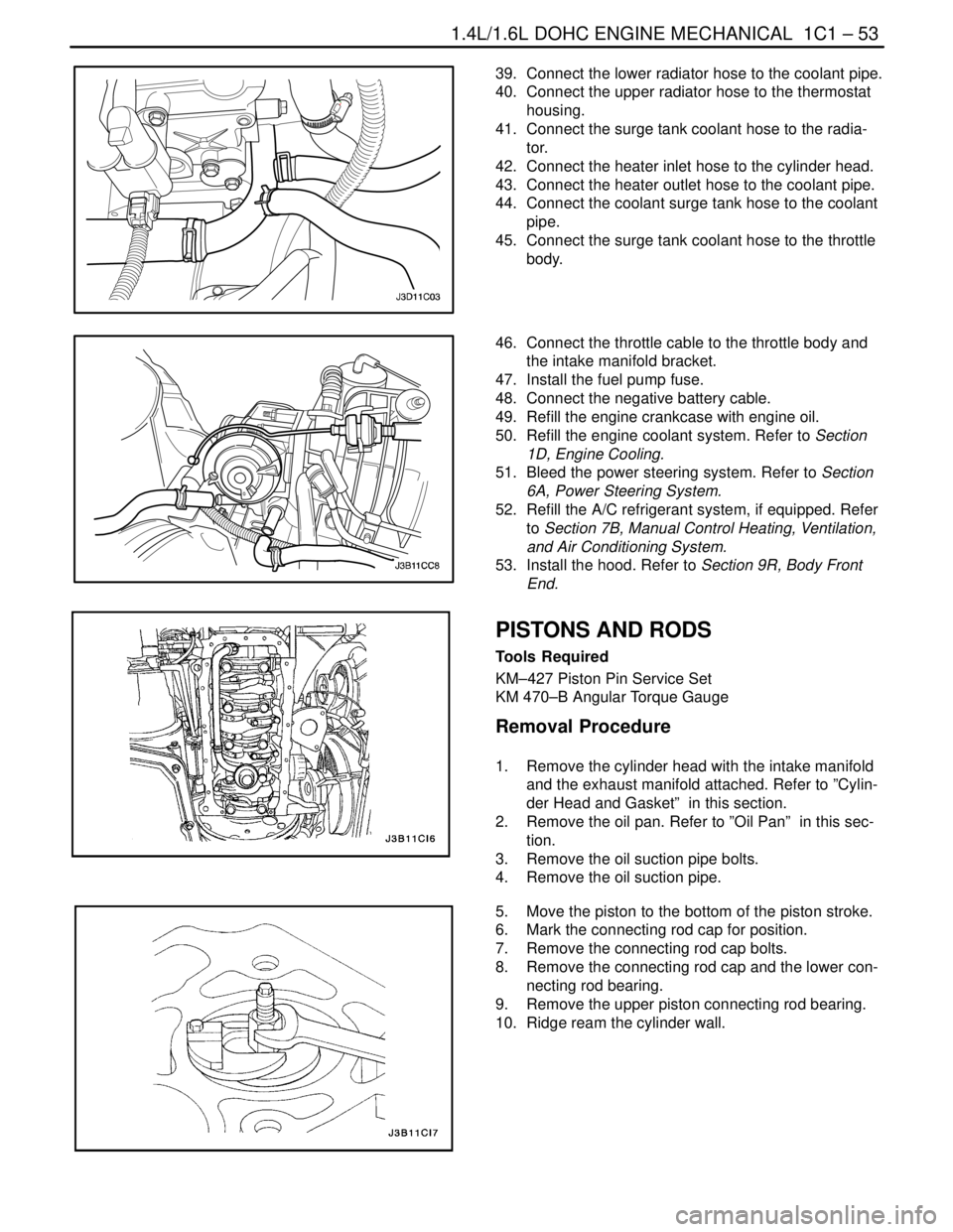
39. Connect the lower radiator hose to the coolant pipe.
40. Connect the upper radiator hose to the thermostat
housing.
41. Connect the surge tank coolant hose to the radia-
tor.
42. Connect the heater inlet hose to the cylinder head.
43. Connect the heater outlet hose to the coolant pipe.
44. Connect the coolant surge tank hose to the coolant
pipe.
45. Connect the surge tank coolant hose to the throttle
body.
46. Connect the throttle cable to the throttle body and
the intake manifold bracket.
47. Install the fuel pump fuse.
48. Connect the negative battery cable.
49. Refill the engine crankcase with engine oil.
50. Refill the engine coolant system. Refer to Section
1D, Engine Cooling.
51. Bleed the power steering system. Refer to Section
6A, Power Steering System.
52. Refill the A/C refrigerant system, if equipped. Refer
to Section 7B, Manual Control Heating, Ventilation,
and Air Conditioning System.
53. Install the hood. Refer to Section 9R, Body Front
End.
PISTONS AND RODS
Tools Required
KM–427 Piston Pin Service Set
KM 470–B Angular Torque Gauge
Removal Procedure
1. Remove the cylinder head with the intake manifold
and the exhaust manifold attached. Refer to ”Cylin-
der Head and Gasket” in this section.
2. Remove the oil pan. Refer to ”Oil Pan” in this sec-
tion.
3. Remove the oil suction pipe bolts.
4. Remove the oil suction pipe.
5. Move the piston to the bottom of the piston stroke.
6. Mark the connecting rod cap for position.
7. Remove the connecting rod cap bolts.
8. Remove the connecting rod cap and the lower con-
necting rod bearing.
9. Remove the upper piston connecting rod bearing.
10. Ridge ream the cylinder wall.
Page 166 of 2643
1C2 – 46I1.8L DOHC ENGINE MECHANICAL
DAEWOO V–121 BL4
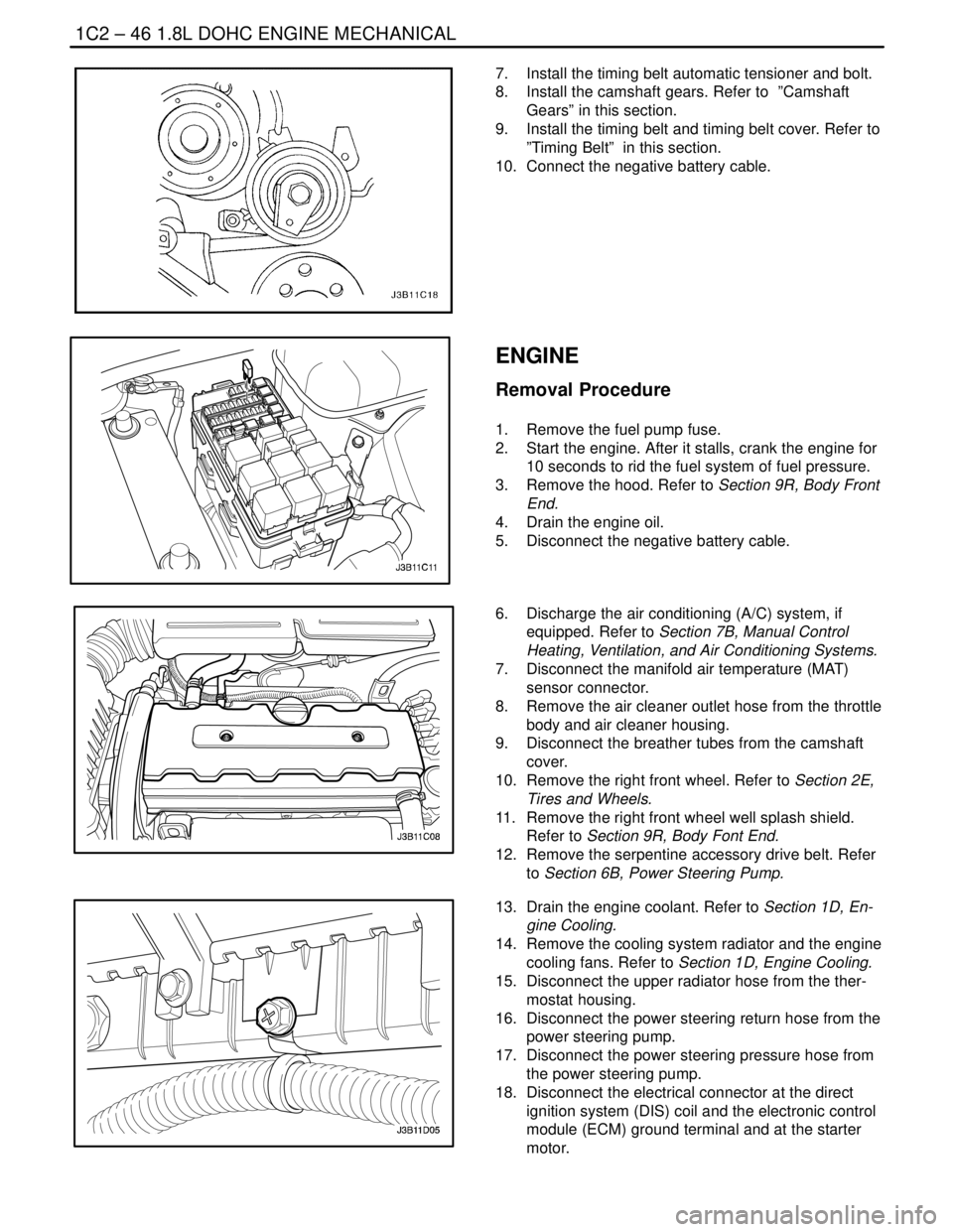
7. Install the timing belt automatic tensioner and bolt.
8. Install the camshaft gears. Refer to ”Camshaft
Gears” in this section.
9. Install the timing belt and timing belt cover. Refer to
”Timing Belt” in this section.
10. Connect the negative battery cable.
ENGINE
Removal Procedure
1. Remove the fuel pump fuse.
2. Start the engine. After it stalls, crank the engine for
10 seconds to rid the fuel system of fuel pressure.
3. Remove the hood. Refer to Section 9R, Body Front
End.
4. Drain the engine oil.
5. Disconnect the negative battery cable.
6. Discharge the air conditioning (A/C) system, if
equipped. Refer to Section 7B, Manual Control
Heating, Ventilation, and Air Conditioning Systems.
7. Disconnect the manifold air temperature (MAT)
sensor connector.
8. Remove the air cleaner outlet hose from the throttle
body and air cleaner housing.
9. Disconnect the breather tubes from the camshaft
cover.
10. Remove the right front wheel. Refer to Section 2E,
Tires and Wheels.
11. Remove the right front wheel well splash shield.
Refer to Section 9R, Body Font End.
12. Remove the serpentine accessory drive belt. Refer
to Section 6B, Power Steering Pump.
13. Drain the engine coolant. Refer to Section 1D, En-
gine Cooling.
14. Remove the cooling system radiator and the engine
cooling fans. Refer to Section 1D, Engine Cooling.
15. Disconnect the upper radiator hose from the ther-
mostat housing.
16. Disconnect the power steering return hose from the
power steering pump.
17. Disconnect the power steering pressure hose from
the power steering pump.
18. Disconnect the electrical connector at the direct
ignition system (DIS) coil and the electronic control
module (ECM) ground terminal and at the starter
motor.
Page 167 of 2643
1.8L DOHC ENGINE MECHANICAL 1C2 – 47
DAEWOO V–121 BL4
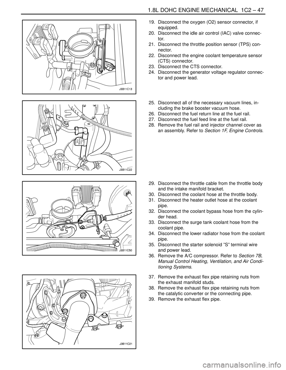
19. Disconnect the oxygen (O2) sensor connector, if
equipped.
20. Disconnect the idle air control (IAC) valve connec-
tor.
21. Disconnect the throttle position sensor (TPS) con-
nector.
22. Disconnect the engine coolant temperature sensor
(CTS) connector.
23. Disconnect the CTS connector.
24. Disconnect the generator voltage regulator connec-
tor and power lead.
25. Disconnect all of the necessary vacuum lines, in-
cluding the brake booster vacuum hose.
26. Disconnect the fuel return line at the fuel rail.
27. Disconnect the fuel feed line at the fuel rail.
28. Remove the fuel rail and injector channel cover as
an assembly. Refer to Section 1F, Engine Controls.
29. Disconnect the throttle cable from the throttle body
and the intake manifold bracket.
30. Disconnect the coolant hose at the throttle body.
31. Disconnect the heater outlet hose at the coolant
pipe.
32. Disconnect the coolant bypass hose from the cylin-
der head.
33. Disconnect the surge tank coolant hose from the
coolant pipe.
34. Disconnect the lower radiator hose from the coolant
pipe.
35. Disconnect the starter solenoid ”S” terminal wire
and power lead.
36. Remove the A/C compressor. Refer to Section 7B,
Manual Control Heating, Ventilation, and Air Condi-
tioning Systems.
37. Remove the exhaust flex pipe retaining nuts from
the exhaust manifold studs.
38. Remove the exhaust flex pipe retaining nuts from
the catalytic converter or the connecting pipe.
39. Remove the exhaust flex pipe.
Page 170 of 2643
1C2 – 50I1.8L DOHC ENGINE MECHANICAL
DAEWOO V–121 BL4
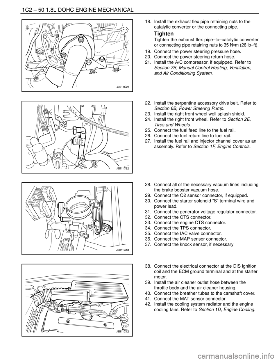
18. Install the exhaust flex pipe retaining nuts to the
catalytic converter or the connecting pipe.
Tighten
Tighten the exhaust flex pipe–to–catalytic converter
or connecting pipe retaining nuts to 35 NSm (26 lb–ft).
19. Connect the power steering pressure hose.
20. Connect the power steering return hose.
21. Install the A/C compressor, if equipped. Refer to
Section 7B, Manual Control Heating, Ventilation,
and Air Conditioning System.
22. Install the serpentine accessory drive belt. Refer to
Section 6B, Power Steering Pump.
23. Install the right front wheel well splash shield.
24. Install the right front wheel. Refer to Section 2E,
Tires and Wheels.
25. Connect the fuel feed line to the fuel rail.
26. Connect the fuel return line to fuel rail.
27. Install the fuel rail and injector channel cover as an
assembly. Refer to Section 1F, Engine Controls.
28. Connect all of the necessary vacuum lines including
the brake booster vacuum hose.
29. Connect the O2 sensor connector, if equipped.
30. Connect the starter solenoid ”S” terminal wire and
power lead.
31. Connect the generator voltage regulator connector.
32. Connect the CTS connector.
33. Connect the engine CTS connector.
34. Connect the TPS connector.
35. Connect the IAC valve connector.
36. Connect the MAP sensor connector.
37. Connect the knock sensor, if necessary
38. Connect the electrical connector at the DIS ignition
coil and the ECM ground terminal and at the starter
motor.
39. Install the air cleaner outlet hose between the
throttle body and the air cleaner housing.
40. Connect the breather tubes to the camshaft cover.
41. Connect the MAT sensor connector.
42. Install the cooling system radiator and the engine
cooling fans. Refer to Section 1D, Engine Cooling.
Page 171 of 2643
1.8L DOHC ENGINE MECHANICAL 1C2 – 51
DAEWOO V–121 BL4
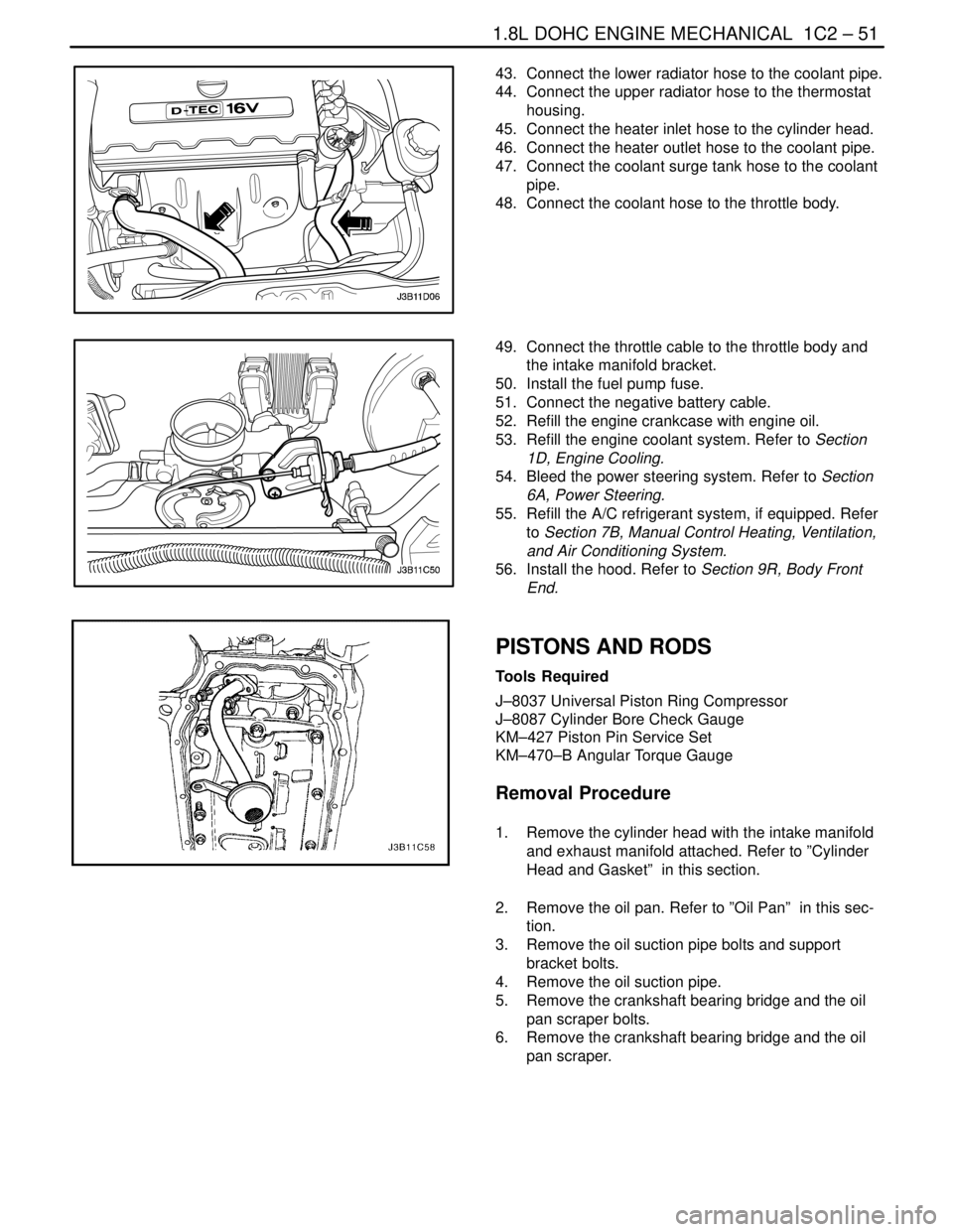
43. Connect the lower radiator hose to the coolant pipe.
44. Connect the upper radiator hose to the thermostat
housing.
45. Connect the heater inlet hose to the cylinder head.
46. Connect the heater outlet hose to the coolant pipe.
47. Connect the coolant surge tank hose to the coolant
pipe.
48. Connect the coolant hose to the throttle body.
49. Connect the throttle cable to the throttle body and
the intake manifold bracket.
50. Install the fuel pump fuse.
51. Connect the negative battery cable.
52. Refill the engine crankcase with engine oil.
53. Refill the engine coolant system. Refer to Section
1D, Engine Cooling.
54. Bleed the power steering system. Refer to Section
6A, Power Steering.
55. Refill the A/C refrigerant system, if equipped. Refer
to Section 7B, Manual Control Heating, Ventilation,
and Air Conditioning System.
56. Install the hood. Refer to Section 9R, Body Front
End.
PISTONS AND RODS
Tools Required
J–8037 Universal Piston Ring Compressor
J–8087 Cylinder Bore Check Gauge
KM–427 Piston Pin Service Set
KM–470–B Angular Torque Gauge
Removal Procedure
1. Remove the cylinder head with the intake manifold
and exhaust manifold attached. Refer to ”Cylinder
Head and Gasket” in this section.
2. Remove the oil pan. Refer to ”Oil Pan” in this sec-
tion.
3. Remove the oil suction pipe bolts and support
bracket bolts.
4. Remove the oil suction pipe.
5. Remove the crankshaft bearing bridge and the oil
pan scraper bolts.
6. Remove the crankshaft bearing bridge and the oil
pan scraper.
Page 213 of 2643

1D – 18IENGINE COOLING
DAEWOO V–121 BL4
GENERAL DESCRIPTION
AND SYSTEM OPERATION
GENERAL DESCRIPTION
The cooling system maintains the engine temperature at
an efficient level during all engine operating conditions.
When the engine is cold, the cooling system cools the en-
gine slowly or not at all. This slow cooling of the engine al-
lows the engine to warm up quickly.
The cooling system includes a radiator and recovery sub-
system, cooling fans, a thermostat and housing, a coolant
pump, and a coolant pump drive belt. The timing belt
drives the coolant pump.
All components must function properly in order for the
cooling system to operate. The coolant pump draws the
coolant from the radiator. The coolant then circulates
through water jackets in the engine block, the intake man-
ifold, and the cylinder head. When the coolant reaches the
operating temperature of the thermostat, the thermostat
opens. The coolant then goes back to the radiator where
it cools.
This system directs some coolant through the hoses to the
heater core. This provides for heating and defrosting. The
surge tank is connected to the radiator to recover the cool-
ant displaced by expansion from the high temperatures.
The surge tank maintains the correct coolant level.
The cooling system for this vehicle has no radiator cap or
filler neck. The coolant is added to the cooling system
through the surge tank.
RADIATOR
This vehicle has a lightweight tube–and–fin aluminum ra-
diator. Plastic tanks are mounted on the right and the left
sides of the radiator core.
On vehicles equipped with automatic transaxles, the
transaxle fluid cooler lines run through the left radiator
tank. A radiator drain cock is on this radiator.
To drain the cooling system, open the drain cock.
SURGE TANK
The surge tank is a transparent plastic reservoir, similar to
the windshield washer reservoir.
The surge tank is connected to the radiator by a hose and
to the engine cooling system by another hose. As the ve-
hicle is driven, the engine coolant heats and expands. The
portion of the engine coolant displaced by this expansion
flows from the radiator and the engine into the surge tank.
The air trapped in the radiator and the engine is degassed
into the surge tank.When the engine stops, the engine coolant cools and con-
tracts. The displaced engine coolant is then drawn back
into the radiator and the engine. This keeps the radiator
filled with the coolant to the desired level at all times and
increases the cooling efficiency.
Maintain the coolant level between the MIN and the MAX
marks on the surge tank when the system is cold.
WATER PUMP
The belt–driven centrifugal water pump consists of an im-
peller, a drive shaft, and a belt pulley. The water pump is
mounted on the front of the transverse–mounted engine,
and is driven by the timing belt.
The impeller is supported by a completely sealed bearing.
The water pump is serviced as an assembly and, there-
fore, cannot be disassembled.
THERMOSTAT
A wax pellet–type thermostat controls the flow of the en-
gine coolant through the engine cooling system. The ther-
mostat is mounted in the thermostat housing to the front
of the cylinder head.
The thermostat stops the flow of the engine coolant from
the engine to the radiator in order to provide faster warm–
up, and to regulate the coolant temperature. The thermo-
stat remains closed while the engine coolant is cold, pre-
venting circulation of the engine coolant through the
radiator. At this point, the engine coolant is allowed to cir-
culate only throughout the heater core to warm it quickly
and evenly.
As the engine warms, the thermostat opens. This allows
the engine coolant to flow through the radiator, where the
heat is dissipated through the radiator. This opening and
closing of the thermostat permits enough engine coolant
to enter the radiator to keep the engine within proper en-
gine temperature operating limits.
The wax pellet in the thermostat is hermetically sealed in
a metal case. The wax element of the thermostat expands
when it is heated and contracts when it is cooled.
As the vehicle is driven and the engine warms, the engine
coolant temperature increases. When the engine coolant
reaches a specified temperature, the wax pellet element
in the thermostat expands and exerts pressure against the
metal case, forcing the valve open. This allows the engine
coolant to flow through the engine cooling system and cool
the engine.
As the wax pellet cools, the contraction allows a spring to
close the valve.
The thermostat begins to open at 87°C (189°F) and is fully
open at 102°C (216°F). The thermostat closes at 86°C
(187°F).