coolant level DAEWOO LACETTI 2004 Service Owner's Manual
[x] Cancel search | Manufacturer: DAEWOO, Model Year: 2004, Model line: LACETTI, Model: DAEWOO LACETTI 2004Pages: 2643, PDF Size: 80.54 MB
Page 672 of 2643
1F – 426IENGINE CONTROLS
DAEWOO V–121 BL4
DIAGNOSTIC TROUBLE CODE (DTC) P0301
CYLINDER 1 MISFURE
System Description
The Engine Control Module (ECM) monitors the crank-
shaft and camshaft positions to detect if the engine is mis-
firing. The ECM looks for a quick drop in crankshaft speed.
This test is executed in blocks of 100 engine revolution
tests. It may take between one to several tests to store a
Diagnostic Trouble Code (DTC) and illuminate the Mal-
function Indicator Lamp (MIL). Under light misfire condi-
tions, it may also take more than one trip to set a DTC. Se-
vere misfire will flash the MIL, indicating that catalyst
damage is possible.
Conditions for Setting the DTC
S Emission threshold is 3%.
S 20 engine cycles have occurred since cranking has
started.
S A/C compressor clutch has not just engaged or dis-
engaged.
S Engine load and engine speed is in a detectable
region and is at or above zero torque.
S Camshaft Position (CMP) sensor is in synchroniza-
tion.
S Exhaust Gas Recirculation (EGR) flow diagnostic is
not in progress.
S Fuel level is greater than 12% of rated tank capac-
ity.
S Decel Fuel Cutoff (DFCO) not active.
S Throttle position change is less than 3% per 125
ms.
S Vehicle has not encountered an abusive engine
speed of 7000 rpm.
S Crankshaft speed patters are normal.
S Throttle position is less than 3% when vehicle
speed is greater than 10 km/h (6 mph).
S Vehicle voltage is between 11 and 16 volts.
S Engine Coolant Temperature (ECT) is between
–7°C (19°F) and 120°C (248°F).
S There is the correct ratio between Crankshaft Posi-
tion (CKP) sensor pulses and CMP sensor pulses.
S DTCs P0106, P0107, P0108, P0117, P0118,
P0122, P0123, P0336, P0337, P0341, P0342 and
P0502 are not set.
Action Taken When the DTC Sets
S The MIL will illuminate after two consecutive ignition
cycles in which the diagnostic runs with the fault
active.
Or
S The MIL will illuminate immediately and flash if mis-
fire is present.S The ECM will record operating conditions at the
time the diagnostic fails. This information will be
stored in the Freeze Frame and Failure Records
buffers.
S A history DTC is stored.
Conditions for Clearing the MIL/DTC
S The MIL will turn off after four consecutive ignition
cycles in which the diagnostic runs without a fault
within the freeze frame conditions that the DTC
failed.
S A history DTC will clear after 40 consecutive warm–
up cycles without a fault.
S The DTC(s) can be cleared by using the scan tool.
S Disconnecting the ECM battery feed for more than
10 seconds.
Diagnostic Aids
An intermittent can also be the result of a defective reluctor
wheel. Remove the CKP sensor and inspect the reluctor
wheel through the sensor mount hole. Check for porosity
and the condition of wheel. If the DTC is intermittent refer
to ”Symptoms Diagnosis” in this section.
Test Description
Number(s) below refer to the step number(s) on the Diag-
nostic Table.
1. The On–Board Diagnostic (EOBD) System Check
prompts the technician to complete some basic
checks and store the freeze frame and failure re-
cords data on the scan tool if applicable. This
creates an electronic copy of the data taken when
the malfunction occurred. The information is then
stored on the scan tool for later reference.
3. A visual/physical inspection should include check-
ing the following components:
S The wiring for proper connections, pinches or
cuts.
S The ECM grounds for being clean and tight.
S The vacuum hoses for splits, kinks, and proper
connections as shown on the Vehicle Emission
Information label.
S Check thoroughly for any type of leak or restric-
tion.
S For air leaks at the throttle body mounting area
and intake manifold sealing surfaces.
5. When all the accumulators are relatively equal, then
the misfire is being caused by something that af-
fects the entire engine. When they are not then the
misfire is being caused by something that is specif-
ic to two or more cylinders.
6. Whenever the misfire is not present operating the
vehicle may be necessary to duplicate the condi-
tions in the Freeze Frame Data in order to detect
Page 677 of 2643
ENGINE CONTROLS 1F – 431
DAEWOO V–121 BL4
DIAGNOSTIC TROUBLE CODE (DTC) P0302
CYLINDER 2 MISFIRE
System Description
The Engine Control Module (ECM) monitors the crank-
shaft and camshaft positions to detect if the engine is mis-
firing. The ECM looks for a quick drop in crankshaft speed.
This test is executed in blocks of 100 engine revolution
tests. It may take between one to several tests to store a
Diagnostic Trouble Code (DTC) and illuminate the Mal-
function Indicator Lamp (MIL). Under light misfire condi-
tions, it may also take more than one trip to set a DTC. Se-
vere misfire will flash the MIL, indicating that catalyst
damage is possible.
Conditions for Setting the DTC
S Emission threshold is 3%.
S 20 engine cycles have occurred since cranking has
started.
S A/C compressor clutch has not just engaged or dis-
engaged.
S Engine load and engine speed is in a detectable
region and is at or above zero torque.
S Camshaft Position (CMP) sensor is in synchroniza-
tion.
S Exhaust Gas Recirculation (EGR) flow diagnostic is
not in progress.
S Fuel level is greater than 12% of rated tank capac-
ity.
S Decel Fuel Cutoff (DFCO) not active.
S Throttle position change is less than 3% per 125
ms.
S Vehicle has not encountered an abusive engine
speed of 7000 rpm.
S Crankshaft speed patters are normal.
S Throttle position is less than 3% when vehicle
speed is greater than 10 km/h (6 mph).
S Vehicle voltage is between 11 and 16 volts.
S Engine Coolant Temperature (ECT) is between
–7°C (19°F) and 120°C (248°F).
S There is the correct ratio between Crankshaft Posi-
tion (CKP) sensor pulses and CMP sensor pulses.
S DTCs P0106, P0107, P0108, P0117, P0118,
P0122, P0123, P0336, P0337, P0341, P0342 and
P0502 are not set.
Action Taken When the DTC Sets
S The MIL will illuminate after two consecutive ignition
cycles in which the diagnostic runs with the fault
active.
Or
S The MIL will illuminate immediately and flash if mis-
fire is present.
S The ECM will record operating conditions at the
time the diagnostic fails. This information will be
stored in the Freeze Frame and Failure Records
buffers.S A history DTC is stored.
Conditions for Clearing the MIL/DTC
S The MIL will turn off after four consecutive ignition
cycles in which the diagnostic runs without a fault
within the freeze frame conditions that the DTC
failed.
S A history DTC will clear after 40 consecutive warm–
up cycles without a fault.
S The DTC(s) can be cleared by using the scan tool.
S Disconnecting the ECM battery feed for more than
10 seconds.
Diagnostic Aids
An intermittent can also be the result of a defective reluctor
wheel. Remove the CKP sensor and inspect the reluctor
wheel through the sensor mount hole. Check for porosity
and the condition of wheel. If the DTC is intermittent refer
to”Symptoms Diagnosis” in this section.
Test Description
Number(s) below refer to the step number(s) on the Diag-
nostic Table.
1. The On–Board Diagnostic (EOBD) System Check
prompts the technician to complete some basic
checks and store the freeze frame and failure re-
cords data on the scan tool if applicable. This
creates an electronic copy of the data taken when
the malfunction occurred. The information is then
stored on the scan tool for later reference.
3. A visual/physical inspection should include check-
ing the following components:
S The wiring for proper connections, pinches or
cuts.
S The ECM grounds for being clean and tight.
S The vacuum hoses for splits, kinks, and proper
connections as shown on the Vehicle Emission
Information label. Check thoroughly for any type
of leak or restriction.
S For air leaks at the throttle body mounting area
and intake manifold sealing surfaces.
5. When all the accumulators are relatively equal, then
the misfire is being caused by something that af-
fects the entire engine. When they are not then the
misfire is being caused by something that is specif-
ic to two or more cylinders.
6. Whenever the misfire is not present operating the
vehicle may be necessary to duplicate the condi-
tions in the Freeze Frame Data in order to detect
misfire. Depending on the engine load, the condi-
tions may have to be maintained for up to 20 sec-
onds. Whenever the misfire accumulators start to
increment, then misfire is present. A history misfire
counter will store the number of misfires that have
occurred until the DTC is cleared.
Page 682 of 2643
1F – 436IENGINE CONTROLS
DAEWOO V–121 BL4
DIAGNOSTIC TROUBLE CODE (DTC) P0303
CYLINDER 3 MISFIRE
System Description
The Engine Control Module (ECM) monitors the crank-
shaft and camshaft positions to detect if the engine is mis-
firing. The ECM looks for a quick drop in crankshaft speed.
This test is executed in blocks of 100 engine revolution
tests. It may take between one to several tests to store a
Diagnostic Trouble Code (DTC) and illuminate the Mal-
function Indicator Lamp (MIL). Under light misfire condi-
tions, it may also take more than one trip to set a DTC. Se-
vere misfire will flash the MIL, indicating that catalyst
damage is possible.
Conditions for Setting the DTC
S Emission threshold is 3%.
S 20 engine cycles have occurred since cranking has
started.
S A/C compressor clutch has not just engaged or dis-
engaged.
S Engine load and engine speed is in a detectable
region and is at or above zero torque.
S Camshaft Position (CMP) sensor is in synchroniza-
tion.
S Exhaust Gas Recirculation (EGR) flow diagnostic is
not in progress.
S Fuel level is greater than 12% of rated tank capac-
ity.
S Decel Fuel Cutoff (DFCO) not active.
S Throttle position change is less than 3% per 125
ms.
S Vehicle has not encountered an abusive engine
speed of 7000 rpm.
S Crankshaft speed patters are normal.
S Throttle position is less than 3% when vehicle
speed is greater than 10 km/h (6 mph).
S Vehicle voltage is between 11 and 16 volts.
S Engine Coolant Temperature (ECT) is between
–7°C (19°F) and 120°C (248°F).
S There is the correct ratio between Crankshaft Posi-
tion (CKP) sensor pulses and CMP sensor pulses.
S DTCs P0106, P0107, P0108, P0117, P0118,
P0122, P0123, P0336, P0337, P0341, P0342 and
P0502 are not set.
Action Taken When the DTC Sets
S The MIL will illuminate after two consecutive ignition
cycles in which the diagnostic runs with the fault
active.
Or
S The MIL will illuminate immediately and flash if mis-
fire is present.
S The ECM will record operating conditions at the
time the diagnostic fails. This information will be
stored in the Freeze Frame and Failure Records
buffers.S A history DTC is stored.
Conditions for Clearing the MIL/DTC
S The MIL will turn off after four consecutive ignition
cycles in which the diagnostic runs without a fault
within the freeze frame conditions that the DTC
failed.
S A history DTC will clear after 40 consecutive warm–
up cycles without a fault.
S The DTC(s) can be cleared by using the scan tool.
S Disconnecting the ECM battery feed for more than
10 seconds.
Diagnostic Aids
An intermittent can also be the result of a defective reluctor
wheel. Remove the CKP sensor and inspect the reluctor
wheel through the sensor mount hole. Check for porosity
and the condition of wheel. If the DTC is intermittent refer
to”Symptoms Diagnosis” in this section.
Test Description
Number(s) below refer to the step number(s) on the Diag-
nostic Table.
1. The On–Board Diagnostic (EOBD) System Check
prompts the technician to complete some basic
checks and store the freeze frame and failure re-
cords data on the scan tool if applicable. This
creates an electronic copy of the data taken when
the malfunction occurred. The information is then
stored on the scan tool for later reference.
3. A visual/physical inspection should include check-
ing the following components:
S The wiring for proper connections, pinches or
cuts.
S The ECM grounds for being clean and tight.
S The vacuum hoses for splits, kinks, and proper
connections as shown on the Vehicle Emission
Information label. Check thoroughly for any type
of leak or restriction.
S For air leaks at the throttle body mounting area
and intake manifold sealing surfaces.
5. When all the accumulators are relatively equal, then
the misfire is being caused by something that af-
fects the entire engine. When they are not then the
misfire is being caused by something that is specif-
ic to two or more cylinders.
6. Whenever the misfire is not present operating the
vehicle may be necessary to duplicate the condi-
tions in the Freeze Frame Data in order to detect
misfire. Depending on the engine load, the condi-
tions may have to be maintained for up to 20 sec-
onds. Whenever the misfire accumulators start to
increment, then misfire is present. A history misfire
counter will store the number of misfires that have
occurred until the DTC is cleared.
Page 687 of 2643
ENGINE CONTROLS 1F – 441
DAEWOO V–121 BL4
DIAGNOSTIC TROUBLE CODE (DTC) P0304
CYLINDER 4 MISFIRE
System Description
The Engine Control Module (ECM) monitors the crank-
shaft and camshaft positions to detect if the engine is mis-
firing. The ECM looks for a quick drop in crankshaft speed.
This test is executed in blocks of 100 engine revolution
tests. It may take between one to several tests to store a
Diagnostic Trouble Code (DTC) and illuminate the Mal-
function Indicator Lamp (MIL). Under light misfire condi-
tions, it may also take more than one trip to set a DTC. Se-
vere misfire will flash the MIL, indicating that catalyst
damage is possible.
Conditions for Setting the DTC
S Emission threshold is 3%.
S 20 engine cycles have occurred since cranking has
started.
S A/C compressor clutch has not just engaged or dis-
engaged.
S Engine load and engine speed is in a detectable
region and is at or above zero torque.
S Camshaft Position (CMP) sensor is in synchroniza-
tion.
S Exhaust Gas Recirculation (EGR) flow diagnostic is
not in progress.
S Fuel level is greater than 12% of rated tank capac-
ity.
S Decel Fuel Cutoff (DFCO) not active.
S Throttle position change is less than 3% per 125
ms.
S Vehicle has not encountered an abusive engine
speed of 7000 rpm.
S Crankshaft speed patters are normal.
S Throttle position is less than 3% when vehicle
speed is greater than 10 km/h (6 mph).
S Vehicle voltage is between 11 and 16 volts.
S Engine Coolant Temperature (ECT) is between
–7°C (19°F) and 120°C (248°F).
S There is the correct ratio between Crankshaft Posi-
tion (CKP) sensor pulses and CMP sensor pulses.
S DTCs P0106, P0107, P0108, P0117, P0118,
P0122, P0123, P0336, P0337, P0341, P0342 and
P0502 are not set.
Action Taken When the DTC Sets
S The MIL will illuminate after two consecutive ignition
cycles in which the diagnostic runs with the fault
active.
Or
S The MIL will illuminate immediately and flash if mis-
fire is present.
S The ECM will record operating conditions at the
time the diagnostic fails. This information will be
stored in the Freeze Frame and Failure Records
buffers.S A history DTC is stored.
Conditions for Clearing the MIL/DTC
S The MIL will turn off after four consecutive ignition
cycles in which the diagnostic runs without a fault
within the freeze frame conditions that the DTC
failed.
S A history DTC will clear after 40 consecutive warm–
up cycles without a fault.
S The DTC(s) can be cleared by using the scan tool.
S Disconnecting the ECM battery feed for more than
10 seconds.
Diagnostic Aids
An intermittent can also be the result of a defective reluctor
wheel. Remove the CKP sensor and inspect the reluctor
wheel through the sensor mount hole. Check for porosity
and the condition of wheel. If the DTC is intermittent refer
to”Symptoms Diagnosis” in this section.
Test Description
Number(s) below refer to the step number(s) on the Diag-
nostic Table.
1. The On–Board Diagnostic (EOBD) System Check
prompts the technician to complete some basic
checks and store the freeze frame and failure re-
cords data on the scan tool if applicable. This
creates an electronic copy of the data taken when
the malfunction occurred. The information is then
stored on the scan tool for later reference.
3. A visual/physical inspection should include check-
ing the following components:
S The wiring for proper connections, pinches or
cuts.
S The ECM grounds for being clean and tight.
S The vacuum hoses for splits, kinks, and proper
connections as shown on the Vehicle Emission
Information label. Check thoroughly for any type
of leak or restriction.
S For air leaks at the throttle body mounting area
and intake manifold sealing surfaces.
5. When all the accumulators are relatively equal, then
the misfire is being caused by something that af-
fects the entire engine. When they are not then the
misfire is being caused by something that is specif-
ic to two or more cylinders.
6. Whenever the misfire is not present operating the
vehicle may be necessary to duplicate the condi-
tions in the Freeze Frame Data in order to detect
misfire. Depending on the engine load, the condi-
tions may have to be maintained for up to 20 sec-
onds. Whenever the misfire accumulators start to
increment, then misfire is present. A history misfire
counter will store the number of misfires that have
occurred until the DTC is cleared.
Page 716 of 2643
1F – 470IENGINE CONTROLS
DAEWOO V–121 BL4
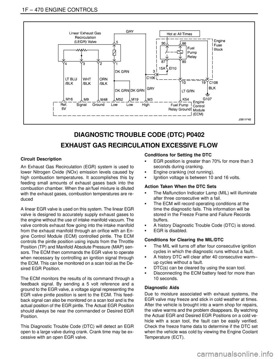
DIAGNOSTIC TROUBLE CODE (DTC) P0402
EXHAUST GAS RECIRCULATION EXCESSIVE FLOW
Circuit Description
An Exhaust Gas Recirculation (EGR) system is used to
lower Nitrogen Oxide (NOx) emission levels caused by
high combustion temperatures. It accomplishes this by
feeding small amounts of exhaust gases back into the
combustion chamber. When the air/fuel mixture is diluted
with the exhaust gases, combustion temperatures are re-
duced
A linear EGR valve is used on this system. The linear EGR
valve is designed to accurately supply exhaust gases to
the engine without the use of intake manifold vacuum. The
valve controls exhaust flow going into the intake manifold
from the exhaust manifold through an orifice with an En-
gine Control Module (ECM) controlled pintle. The ECM
controls the pintle position using inputs from the Throttle
Position (TP) and Manifold Absolute Pressure (MAP) sen-
sors. The ECM then commands the EGR valve to operate
when necessary by controlling an ignition signal through
the ECM. This can be monitored on a scan tool as the De-
sired EGR Position.
The ECM monitors the results of its command through a
feedback signal. By sending a 5 volt reference and a
ground to the EGR valve, a voltage signal representing the
EGR valve pintle position is sent to the ECM. This feed-
back signal can also be monitored on a scan tool and is the
actual position of the EGR pintle. The Actual EGR Position
should always be near the commanded or Desired EGR
Position.
This Diagnostic Trouble Code (DTC) will detect an EGR
open to a large valve during crank. Crank time may be ex-
cessive with an open EGR valve.Conditions for Setting the DTC
S EGR position is greater than 70% for more than 3
seconds during cranking.
S Engine cranking (not running).
S Ignition voltage is between 10 and 16 volts.
Action Taken When the DTC Sets
S The Malfunction Indicator Lamp (MIL) will illuminate
after three consecutive with a fail.
S The ECM will record operating conditions at the
time the diagnostic fails. This information will be
stored in the Freeze Frame and Failure Records
buffers.
S A history Diagnostic Trouble Code (DTC) is stored.
S EGR is disabled.
Conditions for Clearing the MIL/DTC
S The MIL will turns off after four consecutive ignition
cycles in which the diagnostic runs without a fault.
S A history DTC will clear after 40 consecutive warm–
up cycles without a fault.
S DTC(s) can be cleared by using the scan tool.
S Disconnecting the ECM battery feed for more than
10 seconds.
Diagnostic Aids
Due to moisture associated with exhaust systems, the
EGR valve may freeze and stick in cold weather at times.
After the vehicle is brought into a warm shop for repairs,
the valve warms and the problem disappears. By watching
the Actual EGR and Desired EGR Positions on a cold ve-
hicle with a scan tool, the fault can be easily verified.
Check the freeze frame data to determine if the DTC set
when the vehicle was cold by viewing the Engine Coolant
Temperature (ECT).
Page 724 of 2643
1F – 478IENGINE CONTROLS
DAEWOO V–121 BL4
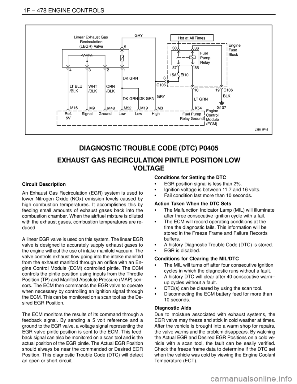
DIAGNOSTIC TROUBLE CODE (DTC) P0405
EXHAUST GAS RECIRCULATION PINTLE POSITION LOW
VOLTAGE
Circuit Description
An Exhaust Gas Recirculation (EGR) system is used to
lower Nitrogen Oxide (NOx) emission levels caused by
high combustion temperatures. It accomplishes this by
feeding small amounts of exhaust gases back into the
combustion chamber. When the air/fuel mixture is diluted
with the exhaust gases, combustion temperatures are re-
duced
A linear EGR valve is used on this system. The linear EGR
valve is designed to accurately supply exhaust gases to
the engine without the use of intake manifold vacuum. The
valve controls exhaust flow going into the intake manifold
from the exhaust manifold through an orifice with an En-
gine Control Module (ECM) controlled pintle. The ECM
controls the pintle position using inputs from the Throttle
Position (TP) and Manifold Absolute Pressure (MAP) sen-
sors. The ECM then commands the EGR valve to operate
when necessary by controlling an ignition signal through
the ECM. This can be monitored on a scan tool as the De-
sired EGR Position.
The ECM monitors the results of its command through a
feedback signal. By sending a 5 volt reference and a
ground to the EGR valve, a voltage signal representing the
EGR valve pintle position is sent to the ECM. This feed-
back signal can also be monitored on a scan tool and is the
actual position of the EGR pintle. The Actual EGR Position
should always be near the commanded or Desired EGR
Position. This diagnostic Trouble Code (DTC) will detect
an open or short circuit.Conditions for Setting the DTC
S EGR position signal is less than 2%.
S Ignition voltage is between 11.7 and 16 volts.
S Fail condition last more than 10 seconds.
Action Taken When the DTC Sets
S The Malfunction Indicator Lamp (MIL) will illuminate
after three consecutive ignition cycle with a fail.
S The ECM will record operating conditions at the
time the diagnostic fails. This information will be
stored in the Freeze Frame and Failure Records
buffers.
S A history Diagnostic Trouble Code (DTC) is stored.
S EGR is disabled.
Conditions for Clearing the MIL/DTC
S The MIL will turns off after four consecutive ignition
cycles in which the diagnostic runs without a fault.
S A history DTC will clear after 40 consecutive warm–
up cycles without a fault.
S DTC(s) can be cleared by using the scan tool.
S Disconnecting the ECM battery feed for more than
10 seconds.
Diagnostic Aids
Due to moisture associated with exhaust systems, the
EGR valve may freeze and stick in cold weather at times.
After the vehicle is brought into a warm shop for repairs,
the valve warms and the problem disappears. By watching
the Actual EGR and Desired EGR Positions on a cold ve-
hicle with a scan tool, the fault can be easily verified.
Check the freeze frame data to determine if the DTC set
when the vehicle was cold by viewing the Engine Coolant
Temperature (ECT).
Page 727 of 2643
ENGINE CONTROLS 1F – 481
DAEWOO V–121 BL4
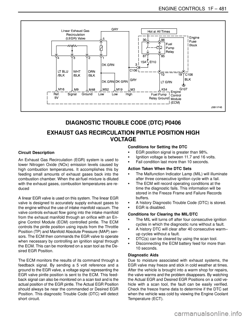
DIAGNOSTIC TROUBLE CODE (DTC) P0406
EXHAUST GAS RECIRCULATION PINTLE POSITION HIGH
VOLTAGE
Circuit Description
An Exhaust Gas Recirculation (EGR) system is used to
lower Nitrogen Oxide (NOx) emission levels caused by
high combustion temperatures. It accomplishes this by
feeding small amounts of exhaust gases back into the
combustion chamber. When the air/fuel mixture is diluted
with the exhaust gases, combustion temperatures are re-
duced
A linear EGR valve is used on this system. The linear EGR
valve is designed to accurately supply exhaust gases to
the engine without the use of intake manifold vacuum. The
valve controls exhaust flow going into the intake manifold
from the exhaust manifold through an orifice with an En-
gine Control Module (ECM) controlled pintle. The ECM
controls the pintle position using inputs from the Throttle
Position (TP) and Manifold Absolute Pressure (MAP) sen-
sors. The ECM then commands the EGR valve to operate
when necessary by controlling an ignition signal through
the ECM. This can be monitored on a scan tool as the De-
sired EGR Position.
The ECM monitors the results of its command through a
feedback signal. By sending a 5 volt reference and a
ground to the EGR valve, a voltage signal representing the
EGR valve pintle position is sent to the ECM. This feed-
back signal can also be monitored on a scan tool and is the
actual position of the EGR pintle. The Actual EGR Position
should always be near the commanded or Desired EGR
Position. This diagnostic Trouble Code (DTC) will detect
short circuit.Conditions for Setting the DTC
S EGR position signal is greater than 98%.
S Ignition voltage is between 11.7 and 16 volts.
S Fail condition last more than 10 seconds.
Action Taken When the DTC Sets
S The Malfunction Indicator Lamp (MIL) will illuminate
after three consecutive ignition cycle with a fail.
S The ECM will record operating conditions at the
time the diagnostic fails. This information will be
stored in the Freeze Frame and Failure Records
buffers.
S A history Diagnostic Trouble Code (DTC) is stored.
S EGR is disabled.
Conditions for Clearing the MIL/DTC
S The MIL will turns off after four consecutive ignition
cycles in which the diagnostic runs without a fault.
S A history DTC will clear after 40 consecutive warm–
up cycles without a fault.
S DTC(s) can be cleared by using the scan tool.
S Disconnecting the ECM battery feed for more than
10 seconds.
Diagnostic Aids
Due to moisture associated with exhaust systems, the
EGR valve may freeze and stick in cold weather at times.
After the vehicle is brought into a warm shop for repairs,
the valve warms and the problem disappears. By watching
the Actual EGR and Desired EGR Positions on a cold ve-
hicle with a scan tool, the fault can be easily verified.
Check the freeze frame data to determine if the DTC set
when the vehicle was cold by viewing the Engine Coolant
Temperature (ECT).
Page 744 of 2643
1F – 498IENGINE CONTROLS
DAEWOO V–121 BL4
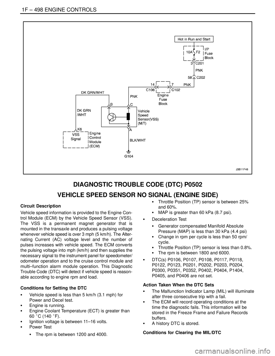
DIAGNOSTIC TROUBLE CODE (DTC) P0502
VEHICLE SPEED SENSOR NO SIGNAL (ENGINE SIDE)
Circuit Description
Vehicle speed information is provided to the Engine Con-
trol Module (ECM) by the Vehicle Speed Sensor (VSS).
The VSS is a permanent magnet generator that is
mounted in the transaxle and produces a pulsing voltage
whenever vehicle speed is over 3 mph (5 km/h). The Alter-
nating Current (AC) voltage level and the number of
pulses increases with vehicle speed. The ECM converts
the pulsing voltage into mph (km/h) and then supplies the
necessary signal to the instrument panel for speedometer/
odometer operation and to the cruise control module and
multi–function alarm module operation. This Diagnostic
Trouble Code (DTC) will detect if vehicle speed is reason-
able according to engine rpm and load.
Conditions for Setting the DTC
S Vehicle speed is less than 5 km/h (3.1 mph) for
Power and Decel test.
S Engine is running.
S Engine Coolant Temperature (ECT) is greater than
60 °C (140 °F).
S Ignition voltage is between 11–16 volts.
S Power Test
S The rpm is between 1200 and 4000.S Throttle Position (TP) sensor is between 25%
and 60%.
S MAP is greater than 60 kPa (8.7 psi).
S Deceleration Test
S Generator compensated Manifold Absolute
Pressure (MAP) is less than 30 kPa (4.4 psi)
S Change in rpm per cycle is less than 50 rpm/
cycle.
S Throttle Position (TP) sensor is less than 0.8%.
S The rpm is between 1800 and 6000.
S DTC(s) P0106, P0107, P0108, P0117, P0118,
P0122, P0123, P0201, P0202, P0203, P0204,
P0300, P0351, P0352, P0402, P0404, P1404,
P0405, and P0406 are not set.
Action Taken When the DTC Sets
S The Malfunction Indicator Lamp (MIL) will illuminate
after three consecutive trip with a fail.
S The ECM will record operating conditions at the
time the diagnostic fails. This information will be
stored in the Freeze Frame and Failure Records
buffers.
S A history DTC is stored.
Conditions for Clearing the MIL/DTC
Page 833 of 2643
ENGINE CONTROLS 1F – 587
DAEWOO V–121 BL4
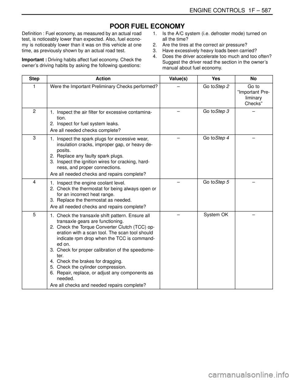
POOR FUEL ECONOMY
Definition : Fuel economy, as measured by an actual road
test, is noticeably lower than expected. Also, fuel econo-
my is noticeably lower than it was on this vehicle at one
time, as previously shown by an actual road test.
Important : Driving habits affect fuel economy. Check the
owner’s driving habits by asking the following questions:1. Is the A/C system (i.e. defroster mode) turned on
all the time?
2. Are the tires at the correct air pressure?
3. Have excessively heavy loads been carried?
4. Does the driver accelerate too much and too often?
Suggest the driver read the section in the owner’s
manual about fuel economy.
Step
ActionValue(s)YesNo
1Were the Important Preliminary Checks performed?–Go toStep 2Go to
”Important Pre-
liminary
Checks”
21. Inspect the air filter for excessive contamina-
tion.
2. Inspect for fuel system leaks.
Are all needed checks complete?–Go toStep 3–
31. Inspect the spark plugs for excessive wear,
insulation cracks, improper gap, or heavy de-
posits.
2. Replace any faulty spark plugs.
3. Inspect the ignition wires for cracking, hard-
ness, and proper connections.
Are all needed checks and repairs complete?–Go toStep 4–
41. Inspect the engine coolant level.
2. Check the thermostat for being always open or
for an incorrect heat range.
3. Replace the thermostat as needed.
Are all needed checks and repairs complete?–Go toStep 5–
51. Check the transaxle shift pattern. Ensure all
transaxle gears are functioning.
2. Check the Torque Converter Clutch (TCC) op-
eration with a scan tool. The scan tool should
indicate rpm drop when the TCC is command-
ed on.
3. Check for proper calibration of the speedome-
ter.
4. Check the brakes for dragging.
5. Check the cylinder compression.
6. Repair, replace, or adjust any components as
needed.
Are all checks and needed repairs complete?–System OK–
Page 872 of 2643
1F – 626IENGINE CONTROLS
DAEWOO V–121 BL4
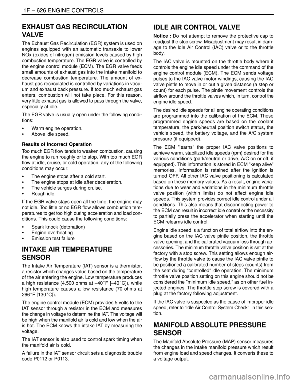
EXHAUST GAS RECIRCULATION
VA LV E
The Exhaust Gas Recirculation (EGR) system is used on
engines equipped with an automatic transaxle to lower
NOx (oxides of nitrogen) emission levels caused by high
combustion temperature. The EGR valve is controlled by
the engine control module (ECM). The EGR valve feeds
small amounts of exhaust gas into the intake manifold to
decrease combustion temperature. The amount of ex-
haust gas recirculated is controlled by variations in vacu-
um and exhaust back pressure. If too much exhaust gas
enters, combustion will not take place. For this reason,
very little exhaust gas is allowed to pass through the valve,
especially at idle.
The EGR valve is usually open under the following condi-
tions:
S Warm engine operation.
S Above idle speed.
Results of Incorrect Operation
Too much EGR flow tends to weaken combustion, causing
the engine to run roughly or to stop. With too much EGR
flow at idle, cruise, or cold operation, any of the following
conditions may occur:
S The engine stops after a cold start.
S The engine stops at idle after deceleration.
S The vehicle surges during cruise.
S Rough idle.
If the EGR valve stays open all the time, the engine may
not idle. Too little or no EGR flow allows combustion tem-
peratures to get too high during acceleration and load con-
ditions. This could cause the following conditions:
S Spark knock (detonation)
S Engine overheating
S Emission test failure
INTAKE AIR TEMPERATURE
SENSOR
The Intake Air Temperature (IAT) sensor is a thermistor,
a resistor which changes value based on the temperature
of the air entering the engine. Low temperature produces
a high resistance (4,500 ohms at –40°F [–40°C]), while
high temperature causes a low resistance (70 ohms at
266°F [130°C]).
The engine control module (ECM) provides 5 volts to the
IAT sensor through a resistor in the ECM and measures
the change in voltage to determine the IAT. The voltage will
be high when the manifold air is cold and low when the air
is hot. The ECM knows the intake IAT by measuring the
voltage.
The IAT sensor is also used to control spark timing when
the manifold air is cold.
A failure in the IAT sensor circuit sets a diagnostic trouble
code P0112 or P0113.
IDLE AIR CONTROL VALVE
Notice : Do not attempt to remove the protective cap to
readjust the stop screw. Misadjustment may result in dam-
age to the Idle Air Control (IAC) valve or to the throttle
body.
The IAC valve is mounted on the throttle body where it
controls the engine idle speed under the command of the
engine control module (ECM). The ECM sends voltage
pulses to the IAC valve motor windings, causing the IAC
valve pintle to move in or out a given distance (a step or
count) for each pulse. The pintle movement controls the
airflow around the throttle valves which, in turn, control the
engine idle speed.
The desired idle speeds for all engine operating conditions
are programmed into the calibration of the ECM. These
programmed engine speeds are based on the coolant
temperature, the park/neutral position switch status, the
vehicle speed, the battery voltage, and the A/C system
pressure (if equipped).
The ECM ”learns” the proper IAC valve positions to
achieve warm, stabilized idle speeds (rpm) desired for the
various conditions (park/neutral or drive, A/C on or off, if
equipped). This information is stored in ECM ”keep alive”
memories. Information is retained after the ignition is
turned OFF. All other IAC valve positioning is calculated
based on these memory values. As a result, engine varia-
tions due to wear and variations in the minimum throttle
valve position (within limits) do not affect engine idle
speeds. This system provides correct idle control under all
conditions. This also means that disconnecting power to
the ECM can result in incorrect idle control or the necessity
to partially press the accelerator when starting until the
ECM relearns idle control.
Engine idle speed is a function of total airflow into the en-
gine based on the IAC valve pintle position, the throttle
valve opening, and the calibrated vacuum loss through ac-
cessories. The minimum throttle valve position is set at the
factory with a stop screw. This setting allows enough air-
flow by the throttle valve to cause the IAC valve pintle to
be positioned a calibrated number of steps (counts) from
the seat during ”controlled” idle operation. The minimum
throttle valve position setting on this engine should not be
considered the ”minimum idle speed,” as on other fuel in-
jected engines. The throttle stop screw is covered with a
plug at the factory following adjustment.
If the IAC valve is suspected as the cause of improper idle
speed, refer to ”Idle Air Control System Check” in this sec-
tion.
MANIFOLD ABSOLUTE PRESSURE
SENSOR
The Manifold Absolute Pressure (MAP) sensor measures
the changes in the intake manifold pressure which result
from engine load and speed changes. It converts these to
a voltage output.