spark plugs DAEWOO LACETTI 2004 Service Owner's Manual
[x] Cancel search | Manufacturer: DAEWOO, Model Year: 2004, Model line: LACETTI, Model: DAEWOO LACETTI 2004Pages: 2643, PDF Size: 80.54 MB
Page 163 of 2643

1.8L DOHC ENGINE MECHANICAL 1C2 – 43
DAEWOO V–121 BL4
CAMSHAFT GEARS
Removal Procedure
1. Disconnect the negative battery cable.
2. Remove the timing belt. Refer to ”Timing Belt” in
this section.
3. Remove the spark plug cover bolts.
4. Remove the spark plug cover.
5. Disconnect the ignition wires from the spark plugs.
6. Disconnect the breather tubes from the camshaft
cover.
7. Remove the camshaft cover bolts.
8. Remove the camshaft cover washers.
9. Remove the camshaft cover and the camshaft cov-
er gasket.
Notice : Take extreme care to prevent any scratches,
nicks or damage to the camshafts.
10. While holding the intake camshaft firmly in place,
remove the intake camshaft gear bolt.
11. Remove the intake camshaft gear.
12. While holding the exhaust camshaft firmly in place,
remove the exhaust camshaft gear bolt.
13. Remove the exhaust camshaft gear.
Installation Procedure
Notice : Take extreme care to prevent any scratches,
nicks or damage to the camshafts.
1. Install the intake camshaft gear.
2. While holding the intake camshaft firmly in place,
install the intake camshaft gear bolt.
Tighten
Tighten the intake camshaft gear bolt to 50 NSm (37
lb–ft) plus 60 degrees and 15 degrees using the angu-
lar torque gauge KM–470–B.
Page 164 of 2643

1C2 – 44I1.8L DOHC ENGINE MECHANICAL
DAEWOO V–121 BL4
3. Install the exhaust camshaft gear.
4. While holding the exhaust camshaft firmly in place,
install the exhaust camshaft gear bolt.
Tighten
Tighten the exhaust camshaft gear bolt to 50 NSm (37
lb–ft) plus 60 degrees and 15 degrees using the angu-
lar torque gauge KM–470–B.
5. Apply a small amount of gasket sealant to the cor-
ners of the front camshaft caps and to the top of
the rear camshaft cover–to–cylinder head seal.
6. Install the camshaft cover and the camshaft cover
gasket.
7. Install the camshaft cover washers.
8. Install the camshaft cover bolts.
Tighten
Tighten the camshaft cover bolts to 8 NSm (71 lb–in).
9. Connect the crankcase breather tubes to the cam-
shaft cover.
10. Connect the ignition wires to the spark plugs.
11. Install the spark plug cover.
12. Install the spark plug cover bolts.
Tighten
Tighten the spark plug cover bolts to 8 NSm (71 lb–in).
13. Install the timing belt. Refer to ”Timing Belt” in this
section.
14. Connect the negative battery cable.
REAR TIMING BELT COVER
Tools Required
KM–470–B Angular Torque Gauge
Removal Procedure
1. Disconnect the negative battery cable.
2. Remove the timing belt. Refer to ”Timing Belt” in
this section.
3. Remove the camshaft gears. Refer to ”Camshaft
Gears” in this section.
4. Remove the timing belt automatic tensioner bolt.
5. Remove the timing belt automatic tensioner.
Page 177 of 2643
1.8L DOHC ENGINE MECHANICAL 1C2 – 57
DAEWOO V–121 BL4
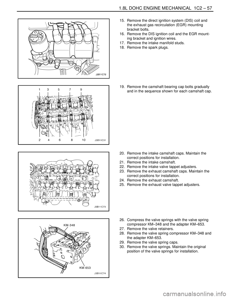
15. Remove the direct ignition system (DIS) coil and
the exhaust gas recirculation (EGR) mounting
bracket bolts.
16. Remove the DIS ignition coil and the EGR mount-
ing bracket and ignition wires.
17. Remove the intake manifold studs.
18. Remove the spark plugs.
19. Remove the camshaft bearing cap bolts gradually
and in the sequence shown for each camshaft cap.
20. Remove the intake camshaft caps. Maintain the
correct positions for installation.
21. Remove the intake camshaft.
22. Remove the intake valve tappet adjusters.
23. Remove the exhaust camshaft caps. Maintain the
correct positions for installation.
24. Remove the exhaust camshaft.
25. Remove the exhaust valve tappet adjusters.
26. Compress the valve springs with the valve spring
compressor KM–348 and the adapter KM–653.
27. Remove the valve retainers.
28. Remove the valve spring compressor KM–348 and
the adapter KM–653.
29. Remove the valve spring caps.
30. Remove the valve springs. Maintain the original
position of the valve springs for installation.
Page 182 of 2643

1C2 – 62I1.8L DOHC ENGINE MECHANICAL
DAEWOO V–121 BL4
14. Install the intake camshaft.
15. Install the intake camshaft bearing caps in their
original positions.
16. Install the exhaust camshaft.
17. Install the exhaust camshaft bearing caps in their
original positions.
18. Install the camshaft bearing cap bolts.
19. Tighten the camshaft bearing cap bolts gradually
and in the sequence shown for each camshaft cap.
Tighten
Tighten the camshaft bearing cap bolts to 8 NSm (71
lb–in).
20. Install the spark plugs.
Tighten
Tighten the spark plugs to 20 NSm (15 lb–ft).
21. Install the DIS coil and EGR mounting bracket.
22. Install the DIS coil and EGR mounting bracket
bolts.
Tighten
Tighten the direct ignition system coil and exhaust
gas recirculation mounting bracket bolts to 25 NSm
(18 lb–ft).
23. Install the intake manifold studs.
24. Install the intake manifold gasket.
25. Install the intake manifold.
26. Install the intake manifold retaining nuts and retain-
ing bolt in the sequence shown.
Tighten
Tighten the intake manifold retaining nuts and retain-
ing bolt to 22 NSm (16 lb–ft).
27. Install the fuel rail assembly. Refer to Section 1F,
Engine Controls.
28. Install the thermostat housing assembly.
29. Install the thermostat housing mounting bolts.
Tighten
Tighten the thermostat housing mounting bolts to 15
NSm (11 lb–ft).
30. Install the coolant bypass housing and mounting
bolts.
Tighten
Tighten the coolant bypass housing bolts to 15 NSm
(11 lb–ft).
Page 184 of 2643
1C2 – 64I1.8L DOHC ENGINE MECHANICAL
DAEWOO V–121 BL4
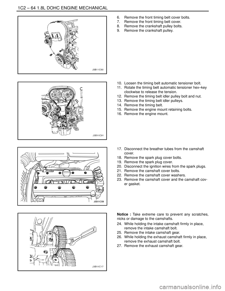
6. Remove the front timing belt cover bolts.
7. Remove the front timing belt cover.
8. Remove the crankshaft pulley bolts.
9. Remove the crankshaft pulley.
10. Loosen the timing belt automatic tensioner bolt.
11. Rotate the timing belt automatic tensioner hex–key
clockwise to release the tension.
12. Remove the timing belt idler pulley bolt and nut.
13. Remove the timing belt idler pulleys.
14. Remove the timing belt.
15. Remove the engine mount retaining bolts.
16. Remove the engine mount.
17. Disconnect the breather tubes from the camshaft
cover.
18. Remove the spark plug cover bolts.
19. Remove the spark plug cover.
20. Disconnect the ignition wires from the spark plugs.
21. Remove the camshaft cover bolts.
22. Remove the camshaft cover washers.
23. Remove the camshaft cover and the camshaft cov-
er gasket.
Notice : Take extreme care to prevent any scratches,
nicks or damage to the camshafts.
24. While holding the intake camshaft firmly in place,
remove the intake camshaft bolt.
25. Remove the intake camshaft gear.
26. While holding the exhaust camshaft firmly in place,
remove the exhaust camshaft bolt.
27. Remove the exhaust camshaft gear.
Page 191 of 2643
1.8L DOHC ENGINE MECHANICAL 1C2 – 71
DAEWOO V–121 BL4
Notice : Take extreme care to prevent any scratches,
nicks or damage to the camshafts.
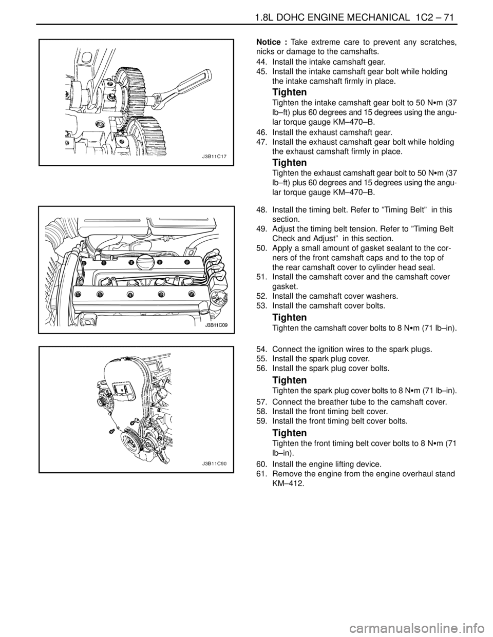
44. Install the intake camshaft gear.
45. Install the intake camshaft gear bolt while holding
the intake camshaft firmly in place.
Tighten
Tighten the intake camshaft gear bolt to 50 NSm (37
lb–ft) plus 60 degrees and 15 degrees using the angu-
lar torque gauge KM–470–B.
46. Install the exhaust camshaft gear.
47. Install the exhaust camshaft gear bolt while holding
the exhaust camshaft firmly in place.
Tighten
Tighten the exhaust camshaft gear bolt to 50 NSm (37
lb–ft) plus 60 degrees and 15 degrees using the angu-
lar torque gauge KM–470–B.
48. Install the timing belt. Refer to ”Timing Belt” in this
section.
49. Adjust the timing belt tension. Refer to ”Timing Belt
Check and Adjust” in this section.
50. Apply a small amount of gasket sealant to the cor-
ners of the front camshaft caps and to the top of
the rear camshaft cover to cylinder head seal.
51. Install the camshaft cover and the camshaft cover
gasket.
52. Install the camshaft cover washers.
53. Install the camshaft cover bolts.
Tighten
Tighten the camshaft cover bolts to 8 NSm (71 lb–in).
54. Connect the ignition wires to the spark plugs.
55. Install the spark plug cover.
56. Install the spark plug cover bolts.
Tighten
Tighten the spark plug cover bolts to 8 NSm (71 lb–in).
57. Connect the breather tube to the camshaft cover.
58. Install the front timing belt cover.
59. Install the front timing belt cover bolts.
Tighten
Tighten the front timing belt cover bolts to 8 NSm (71
lb–in).
60. Install the engine lifting device.
61. Remove the engine from the engine overhaul stand
KM–412.
Page 331 of 2643
ENGINE CONTROLS 1F – 85
DAEWOO V–121 BL4
IGNITION SYSTEM CHECK (1.4L/1.6L DOHC)
Circuit Description
The Electronic Ignition (EI) system uses a waste spark
method of spark distribution. In this type of EI system, the
Crankshaft Position (CKP) sensor is mounted to the oil
pump near a slotted wheel that is a part of the crankshaft
pulley. The CKP sensor sends reference pulses to the en-
gine control module (ECM). The ECM then triggers the EI
system ignition coil. Once the ECM triggers the EI system
ignition coil, both of the connected spark plugs fire at the
same time. One cylinder is on its compression stroke at
the same time that the other is on the exhaust stroke, re-
sulting in lower energy needed to fire the spark plug in the
cylinder on its exhaust stroke.
This leaves the remainder of the high voltage to be used
to fire the spark plug in the cylinder on its compression
stroke. Since the CKP sensor is in a fixed position, timing
adjustments are not possible or needed.
Test Description
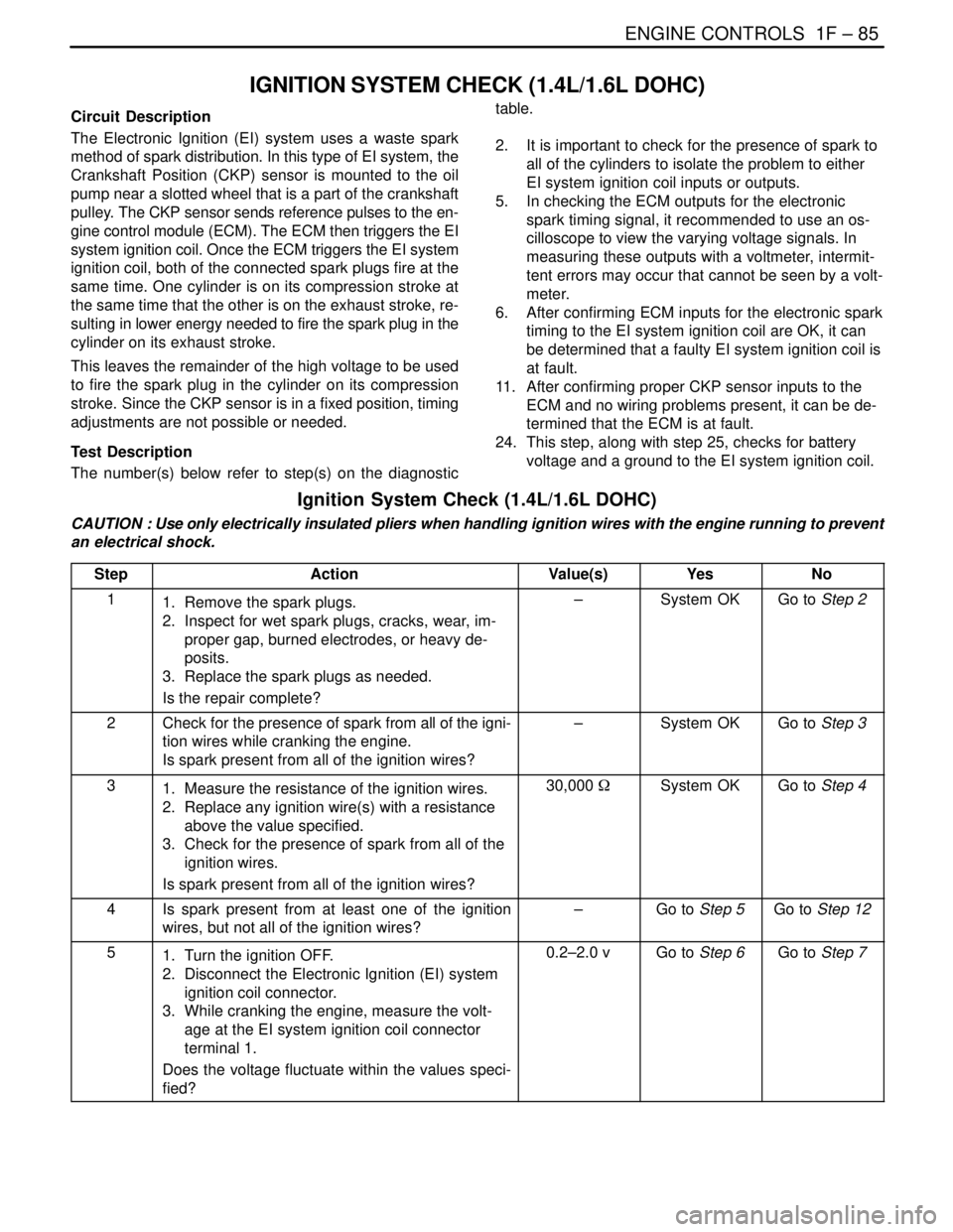
The number(s) below refer to step(s) on the diagnostictable.
2. It is important to check for the presence of spark to
all of the cylinders to isolate the problem to either
EI system ignition coil inputs or outputs.
5. In checking the ECM outputs for the electronic
spark timing signal, it recommended to use an os-
cilloscope to view the varying voltage signals. In
measuring these outputs with a voltmeter, intermit-
tent errors may occur that cannot be seen by a volt-
meter.
6. After confirming ECM inputs for the electronic spark
timing to the EI system ignition coil are OK, it can
be determined that a faulty EI system ignition coil is
at fault.
11. After confirming proper CKP sensor inputs to the
ECM and no wiring problems present, it can be de-
termined that the ECM is at fault.
24. This step, along with step 25, checks for battery
voltage and a ground to the EI system ignition coil.
Ignition System Check (1.4L/1.6L DOHC)
CAUTION : Use only electrically insulated pliers when handling ignition wires with the engine running to prevent
an electrical shock.
Step
ActionValue(s)YesNo
11. Remove the spark plugs.
2. Inspect for wet spark plugs, cracks, wear, im-
proper gap, burned electrodes, or heavy de-
posits.
3. Replace the spark plugs as needed.
Is the repair complete?–System OKGo to Step 2
2Check for the presence of spark from all of the igni-
tion wires while cranking the engine.
Is spark present from all of the ignition wires?–System OKGo to Step 3
31. Measure the resistance of the ignition wires.
2. Replace any ignition wire(s) with a resistance
above the value specified.
3. Check for the presence of spark from all of the
ignition wires.
Is spark present from all of the ignition wires?30,000 WSystem OKGo to Step 4
4Is spark present from at least one of the ignition
wires, but not all of the ignition wires?–Go to Step 5Go to Step 12
51. Turn the ignition OFF.
2. Disconnect the Electronic Ignition (EI) system
ignition coil connector.
3. While cranking the engine, measure the volt-
age at the EI system ignition coil connector
terminal 1.
Does the voltage fluctuate within the values speci-
fied?0.2–2.0 vGo to Step 6Go to Step 7
Page 334 of 2643

1F – 88IENGINE CONTROLS
DAEWOO V–121 BL4
IGNITION SYSTEM CHECK (1.8L DOHC)
Circuit Description
The Electronic Ignition (EI) system uses a waste spark
method of spark distribution. In this type of EI system, the
Crankshaft Position (CKP) sensor is mounted to the oil
pump near a slotted wheel that is a part of the crankshaft
pulley. The CKP sensor sends reference pulses to the en-
gine control module (ECM). The ECM then triggers the EI
system ignition coil. Once the ECM triggers the EI system
ignition coil, both of the connected spark plugs fire at the
same time. One cylinder is on its compression stroke at
the same time that the other is on the exhaust stroke, re-
sulting in lower energy needed to fire the spark plug in the
cylinder on its exhaust stroke.
This leaves the remainder of the high voltage to be used
to fire the spark plug in the cylinder on its compression
stroke. Since the CKP sensor is in a fixed position, timing
adjustments are not possible or needed.
Test Description
The number(s) below refer to step(s) on the diagnostictable.
2. It is important to check for the presence of spark to
all of the cylinders to isolate the problem to either
EI system ignition coil inputs or outputs.
5. In checking the ECM outputs for the electronic
spark timing signal, it recommended to use an os-
cilloscope to view the varying voltage signals. In
measuring these outputs with a voltmeter, intermit-
tent errors may occur that cannot be seen by a volt-
meter.
6. After confirming ECM inputs for the electronic spark
timing to the EI system ignition coil are OK, it can
be determined that a faulty EI system ignition coil is
at fault.
11. After confirming proper CKP sensor inputs to the
ECM and no wiring problems present, it can be de-
termined that the ECM is at fault.
24. This step, along with step 25, checks for battery
voltage and a ground to the EI system ignition coil.
Page 335 of 2643
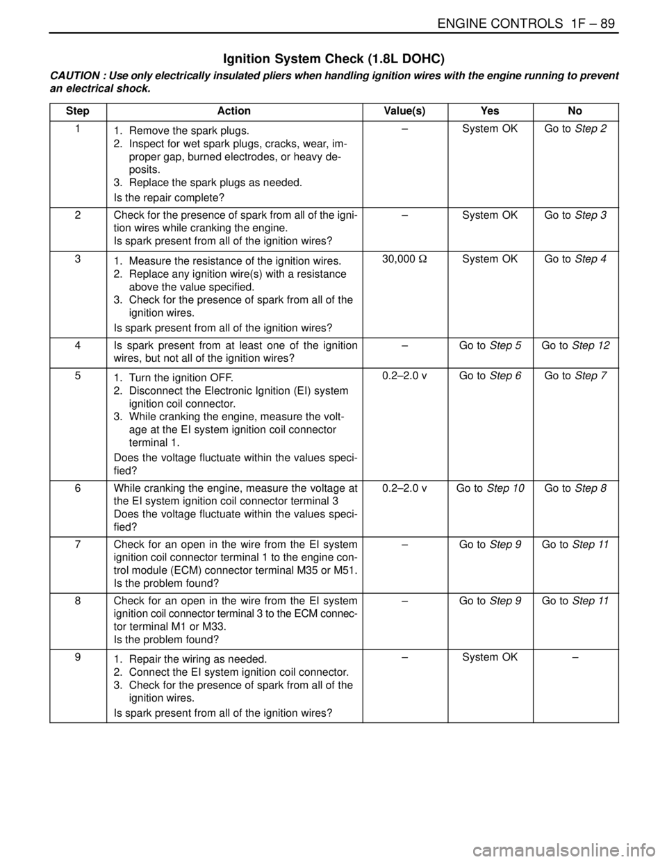
ENGINE CONTROLS 1F – 89
DAEWOO V–121 BL4
Ignition System Check (1.8L DOHC)
CAUTION : Use only electrically insulated pliers when handling ignition wires with the engine running to prevent
an electrical shock.
Step
ActionValue(s)YesNo
11. Remove the spark plugs.
2. Inspect for wet spark plugs, cracks, wear, im-
proper gap, burned electrodes, or heavy de-
posits.
3. Replace the spark plugs as needed.
Is the repair complete?–System OKGo to Step 2
2Check for the presence of spark from all of the igni-
tion wires while cranking the engine.
Is spark present from all of the ignition wires?–System OKGo to Step 3
31. Measure the resistance of the ignition wires.
2. Replace any ignition wire(s) with a resistance
above the value specified.
3. Check for the presence of spark from all of the
ignition wires.
Is spark present from all of the ignition wires?30,000 WSystem OKGo to Step 4
4Is spark present from at least one of the ignition
wires, but not all of the ignition wires?–Go to Step 5Go to Step 12
51. Turn the ignition OFF.
2. Disconnect the Electronic Ignition (EI) system
ignition coil connector.
3. While cranking the engine, measure the volt-
age at the EI system ignition coil connector
terminal 1.
Does the voltage fluctuate within the values speci-
fied?0.2–2.0 vGo to Step 6Go to Step 7
6While cranking the engine, measure the voltage at
the EI system ignition coil connector terminal 3
Does the voltage fluctuate within the values speci-
fied?0.2–2.0 vGo to Step 10Go to Step 8
7Check for an open in the wire from the EI system
ignition coil connector terminal 1 to the engine con-
trol module (ECM) connector terminal M35 or M51.
Is the problem found?–Go to Step 9Go to Step 11
8Check for an open in the wire from the EI system
ignition coil connector terminal 3 to the ECM connec-
tor terminal M1 or M33.
Is the problem found?–Go to Step 9Go to Step 11
91. Repair the wiring as needed.
2. Connect the EI system ignition coil connector.
3. Check for the presence of spark from all of the
ignition wires.
Is spark present from all of the ignition wires?–System OK–
Page 435 of 2643

ENGINE CONTROLS 1F – 189
DAEWOO V–121 BL4
StepNo Yes Value(s) Action
71. Turn the engine OFF.
2. Install a fuel pressure gauge to the fuel rail.
3. Observe the fuel pressure with the engine run-
ning.
Is the fuel pressure within the specified value?284–325 kPa
(41–47 psi)Go to Step 8Go to
”Fuel System
Diagnosis”
8Check the fuel for contamination.
Is the fuel OK?–Go to Step 9Go to Step 10
9Check for a basic engine problem and repair as nec-
essary.
Is the repair complete?–Go to Step 27–
10Replace the contaminated fuel.
Is the repair complete?–Go to Step 27–
111. Turn the engine OFF.
2. Disconnect the fuel injector harness connector.
3. Install a spark tester on cylinder #1 spark plug
cable.
4. Crank the engine and check for spark.
5. Repeat the above procedure on cylinders #2,
#3 and #4.
Is a spark observed on all four spark plug cables?–Go to Step 12Go to Step 20
12Replace any malfunctioning spark plugs if neces-
sary.
Is the repair complete?–Go to Step 27Go to Step 13
131. Turn the engine OFF.
2. Disconnect the fuel injector connectors from
the injectors.
3. Install an injector test light on the injector har-
ness connector for the cylinders that had mis-
fired.
4. Crank the engine and note the test light.
Does the injector test light blink?–Go to Step 14Go to Step 15
14Perform the Fuel Injector Balance Test.
Are the fuel injectors OK?–Go to Step 9Go to Step 16
151. Disconnect the injector test light.
2. With a test light connected to ground, probe
the ignition feed terminal 2 of the injector har-
ness connector for each cylinder that had mis-
fire.
3. Crank the engine.
Does the test light illuminate?–Go to Step 17Go to Step 19
16Replace any malfunctioning fuel injectors.
Is the repair complete?Go to Step 27–
17Check the affected fuel injector driver circuit at termi-
nals 59, 89, 90, and 60 for an open, short, or short
to voltage.
Is a problem found?–Go to Step 18Go to Step 24
18Repair the open or the shorted fuel injector driver cir-
cuit.
Is the repair complete?–Go to Step 27–