Front DAEWOO LACETTI 2004 Service Repair Manual
[x] Cancel search | Manufacturer: DAEWOO, Model Year: 2004, Model line: LACETTI, Model: DAEWOO LACETTI 2004Pages: 2643, PDF Size: 80.54 MB
Page 2569 of 2643
6–4 FRAME DOOR OPENING, DOOR AND SIDE PANEL OUTER NUBIRA/LACETTI
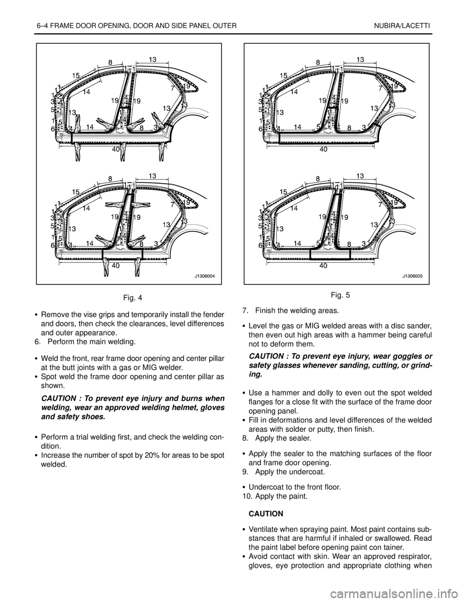
Fig. 4
S Remove the vise grips and temporarily install the fender
and doors, then check the clearances, level differences
and outer appearance.
6. Perform the main welding.
S Weld the front, rear frame door opening and center pillar
at the butt joints with a gas or MIG welder.
S Spot weld the frame door opening and center pillar as
shown.
CAUTION : To prevent eye injury and burns when
welding, wear an approved welding helmet, gloves
and safety shoes.
S Perform a trial welding first, and check the welding con-
dition.
S Increase the number of spot by 20% for areas to be spot
welded.Fig. 5
7. Finish the welding areas.
S Level the gas or MIG welded areas with a disc sander,
then even out high areas with a hammer being careful
not to deform them.
CAUTION : To prevent eye injury, wear goggles or
safety glasses whenever sanding, cutting, or grind-
ing.
S Use a hammer and dolly to even out the spot welded
flanges for a close fit with the surface of the frame door
opening panel.
S Fill in deformations and level differences of the welded
areas with solder or putty, then finish.
8. Apply the sealer.
S Apply the sealer to the matching surfaces of the floor
and frame door opening.
9. Apply the undercoat.
S Undercoat to the front floor.
10. Apply the paint.
CAUTION
S Ventilate when spraying paint. Most paint contains sub-
stances that are harmful if inhaled or swallowed. Read
the paint label before opening paint con tainer.
S Avoid contact with skin. Wear an approved respirator,
gloves, eye protection and appropriate clothing when
Page 2579 of 2643
7–2 FENDER, HOOD, TAILGATE AND TRUNK LID NUBIRA/LACETTI
1. FENDER
1–1. REPAIR PROCEDURE
1. Remove the related parts.
S Front bumper and mud guard.
.
2. Remove the fender
.
3. Preparation of the new fender.
S Preparation of the new fender and check damaged
areas.
.
4. Apply the paint.
.
CAUTION
S Ventilate when spraying paint. Most paint contains sub-
stances that are harmful if inhaled or swallowed, Read
the paint label before opening paint container.
S Avoid contact with skin, Wear an approved respirator,
gloves, eye protection and appropriate clothing when
painting.
S Paint is flammable. Store in a safe place, and keep it
away from sparks, flames or cigarettes.
5. Apply the mastic sealer.
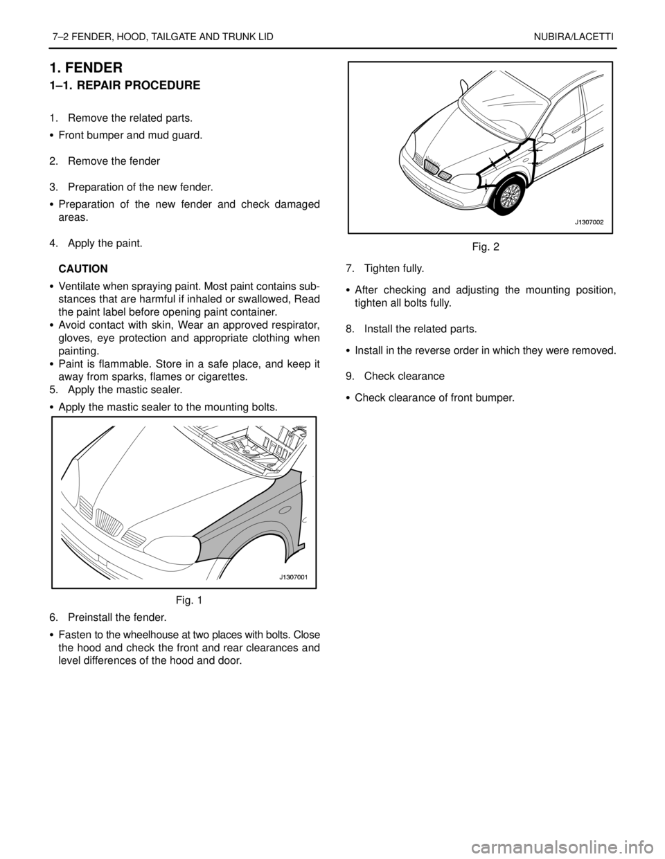
S Apply the mastic sealer to the mounting bolts.
Fig. 1
6. Preinstall the fender.
S Fasten to the wheelhouse at two places with bolts. Close
the hood and check the front and rear clearances and
level differences of the hood and door.
Fig. 2
7. Tighten fully.
S After checking and adjusting the mounting position,
tighten all bolts fully.
.
8. Install the related parts.
S Install in the reverse order in which they were removed.
.
9. Check clearance
S Check clearance of front bumper.
Page 2580 of 2643
NUBIRA/LACETTI FENDER, HOOD, TAILGATE AND TRUNK LID 7–3
2. HOOD
2–1. REPAIR PROCEDURE
1. Remove the related parts.
2. Remove the hood.
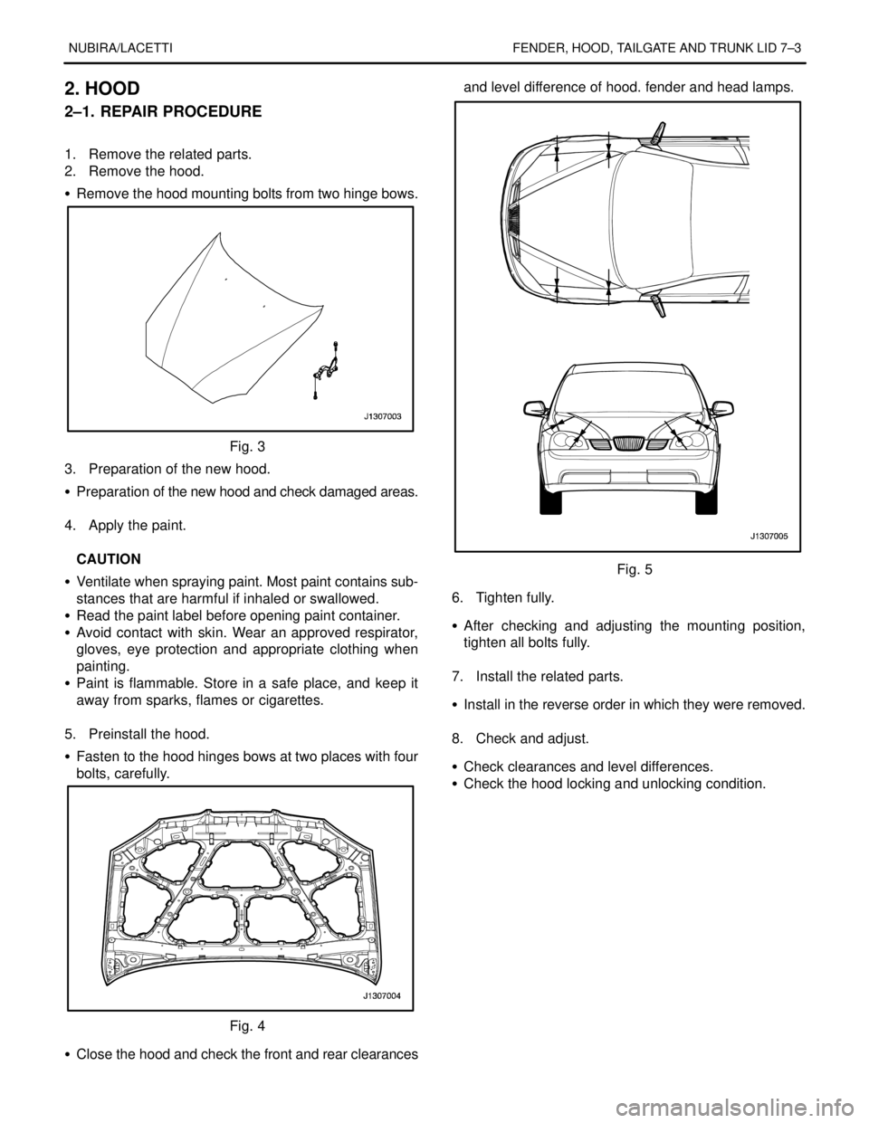
S Remove the hood mounting bolts from two hinge bows.
Fig. 3
3. Preparation of the new hood.
S Preparation of the new hood and check damaged areas.
.
4. Apply the paint.
.
CAUTION
S Ventilate when spraying paint. Most paint contains sub-
stances that are harmful if inhaled or swallowed.
S Read the paint label before opening paint container.
S Avoid contact with skin. Wear an approved respirator,
gloves, eye protection and appropriate clothing when
painting.
S Paint is flammable. Store in a safe place, and keep it
away from sparks, flames or cigarettes.
.
5. Preinstall the hood.
S Fasten to the hood hinges bows at two places with four
bolts, carefully.
Fig. 4
S Close the hood and check the front and rear clearancesand level difference of hood. fender and head lamps.
Fig. 5
6. Tighten fully.
S After checking and adjusting the mounting position,
tighten all bolts fully.
.
7. Install the related parts.
S Install in the reverse order in which they were removed.
.
8. Check and adjust.
S Check clearances and level differences.
S Check the hood locking and unlocking condition.
Page 2584 of 2643

NUBIRA/LACETTIBODY DIMENSION 8–1
SECTION 8
BODY DIMENSION
CONTENTS
1. BODY DRAWING 8 – 2. . . . . . . . . . . . . . . . . . . . . . . . . . . . . . . . . . . . . . . . . . . . . . . . . . .
1.1.UNDER BODY8–2 . . . . . . . . . . . . . . . . . . . . . . . . . . . . . . . . . . . . . . . . . . . . . . . . . . . . . . . . . . . . . . . . . . . . . . . . . . . . . . . . .
1.2.FRONT PANEL8–7 . . . . . . . . . . . . . . . . . . . . . . . . . . . . . . . . . . . . . . . . . . . . . . . . . . . . . . . . . . . . . . . . . . . . . . . . . . . . . . . .
1.3.ENGINE ROOM8–8 . . . . . . . . . . . . . . . . . . . . . . . . . . . . . . . . . . . . . . . . . . . . . . . . . . . . . . . . . . . . . . . . . . . . . . . . . . . . . . . .
1.4.BACK PANEL LOWER8–9 . . . . . . . . . . . . . . . . . . . . . . . . . . . . . . . . . . . . . . . . . . . . . . . . . . . . . . . . . . . . . . . . . . . . . . . . .
1.5.SIDE OUTER8–11 . . . . . . . . . . . . . . . . . . . . . . . . . . . . . . . . . . . . . . . . . . . . . . . . . . . . . . . . . . . . . . . . . . . . . . . . . . . . . . . . .
2. REPAIR DRAWING 8 – 13. . . . . . . . . . . . . . . . . . . . . . . . . . . . . . . . . . . . . . . . . . . . . . . .
2.1.FRAME DOOR OPENING8–13 . . . . . . . . . . . . . . . . . . . . . . . . . . . . . . . . . . . . . . . . . . . . . . . . . . . . . . . . . . . . . . . . . . . . . .
2.2.WINDSHIELD AND REAR GLASS8–15 . . . . . . . . . . . . . . . . . . . . . . . . . . . . . . . . . . . . . . . . . . . . . . . . . . . . . . . . . . . . . .
3. GAP CHART 8 – 17. . . . . . . . . . . . . . . . . . . . . . . . . . . . . . . . . . . . . . . . . . . . . . . . . . . . . .
Page 2587 of 2643
8–4 BODY DIMENSIONNUBIRA/LACETTI
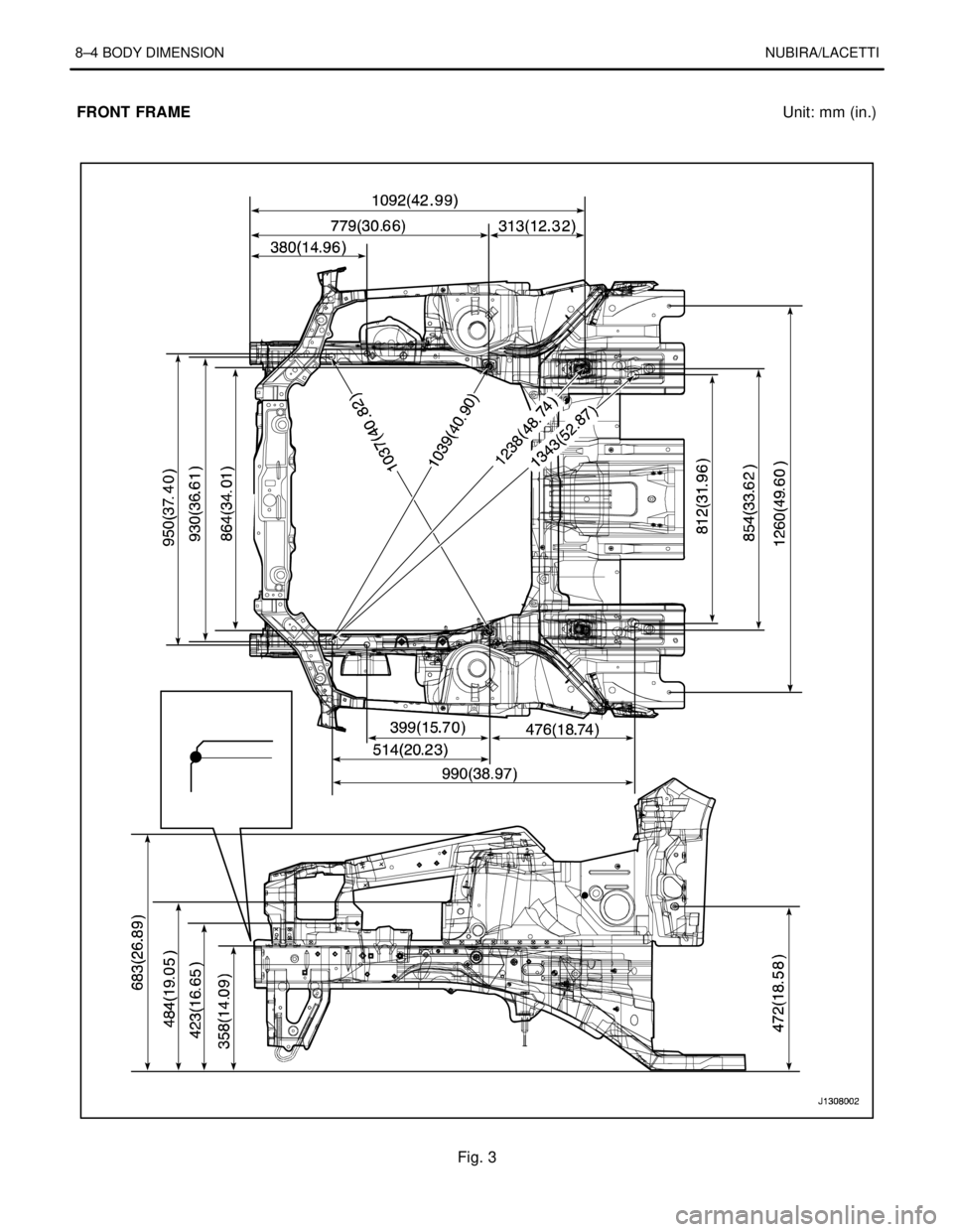
FRONT FRAMEUnit: mm (in.)
Fig. 3
Page 2590 of 2643
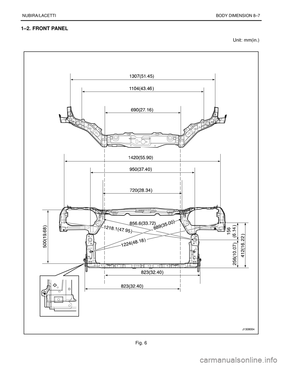
NUBIRA/LACETTIBODY DIMENSION 8–7
1–2. FRONT PANEL
Unit: mm(in.)
Fig. 6
Page 2616 of 2643

NUBIRA/LACETTI SEALING, CAULKING AND DEADNER 9–13
FRONT & REAR DOOR
Fig. 12 Front & Rear Door