fuel pressure DAEWOO NUBIRA 2004 Service Repair Manual
[x] Cancel search | Manufacturer: DAEWOO, Model Year: 2004, Model line: NUBIRA, Model: DAEWOO NUBIRA 2004Pages: 2643, PDF Size: 80.54 MB
Page 870 of 2643
1F – 624IENGINE CONTROLS
DAEWOO V–121 BL4
Because of the constant measuring and adjusting of the
air/fuel ratio, the fuel injection system is called a ”closed
loop” system.
The ECM uses voltage inputs from several sensors to de-
termine how much fuel to provide to the engine. The fuel
is delivered under one of several conditions, called
”modes.”
Starting Mode
When the ignition is turned ON, the ECM turns the fuel
pump relay on for two seconds. The fuel pump then builds
fuel pressure. The ECM also checks the Engine Coolant
Temperature (ECT) sensor and the Throttle Position (TP)
sensor and determines the proper air/fuel ratio for starting
the engine. This ranges from 1.5 to 1 at –97 °F (–36 °C)
coolant temperature to 14.7 to 1 at 201 °F (94 °C) coolant
temperature. The ECM controls the amount of fuel deliv-
ered in the starting mode by changing how long the fuel in-
jector is turned on and off. This is done by ”pulsing” the fuel
injectors for very short times.
Clear Flood Mode
If the engine floods with excessive fuel, it may be cleared
by pushing the accelerator pedal down all the way. The
ECM will then completely turn off the fuel by eliminating
any fuel injector signal. The ECM holds this injector rate
as long as the throttle stays wide open and the engine is
below approximately 400. If the throttle position becomes
less than approximately 80 percent, the ECM returns to
the starting mode.
Run Mode
The run mode has two conditions called ”open loop” and
”closed loop.”
Open Loop
When the engine is first started and it is above 400 rpm,
the system goes into ”open loop” operation. In ”open loop,”
the ECM ignores the signal from the HO2S and calculates
the air/fuel ratio based on inputs from the ECT sensor and
the MAP sensor. The sensor stays in ”open loop” until the
following conditions are met:
S The HO2S sensor has a varying voltage output,
showing that it is hot enough to operate properly.
S The ECT sensor is above a specified temperature.
S A specific amount of time has elapsed after starting
the engine.
Closed Loop
The specific values for the above conditions vary with dif-
ferent engines and are stored in the Electronically Eras-
able Programmable Read–Only Memory (EEPROM).
When these conditions are met, the system goes into
”closed loop” operation. In ”closed loop,” the ECM calcu-
lates the air/fuel ratio (fuel injector on–time) based on the
signal from the oxygen sensor. This allows the air/fuel ratio
to stay very close to 14.7 to 1.Acceleration Mode
The ECM responds to rapid changes in throttle position
and airflow and provides extra fuel.
Deceleration Mode
The ECM responds to changes in throttle position and air-
flow and reduces the amount of fuel. When deceleration
is very fast, the ECM can cut off fuel completely for short
periods of time.
Battery Voltage Correction Mode
When battery voltage is low, the ECM can compensate for
a weak spark delivered by the ignition module by using the
following methods:
S Increasing the fuel injector pulse width.
S Increasing the idle speed rpm.
S Increasing the ignition dwell time.
Fuel Cut–Off Mode
No fuel is delivered by the fuel injectors when the ignition
is OFF. This prevents dieseling or engine run–on. Also, the
fuel is not delivered if there are no reference pulses re-
ceived from the central power supply. This prevents flood-
ing.
EVAPORATIVE EMISSION CONTROL
SYSTEM OPERATION
The basic Evaporative (EVAP) Emission control system
used is the charcoal canister storage method. This meth-
od transfers fuel vapor from the fuel tank to an activated
carbon (charcoal) storage device (canister) to hold the va-
pors when the vehicle is not operating. When the engine
is running, the fuel vapor is purged from the carbon ele-
ment by intake airflow and consumed in the normal com-
bustion process.
Gasoline vapors from the fuel tank flow into the tube la-
beled TANK. These vapors are absorbed into the carbon.
The canister is purged by the engine control module
(ECM) when the engine has been running for a specified
amount of time. Air is drawn into the canister and mixed
with the vapor. This mixture is then drawn into the intake
manifold.
The ECM supplies a ground to energize the EVAP emis-
sion canister purge solenoid valve. This valve is Pulse
Width Modulated (PWM) or turned on and off several
times a second. The EVAP emission canister purge PWM
duty cycle varies according to operating conditions deter-
mined by mass airflow, fuel trim, and intake air tempera-
ture.
Poor idle, stalling, and poor driveability can be caused by
the following conditions:
S An inoperative EVAP emission canister purge sole-
noid valve.
S A damaged canister.
S Hoses that are split, cracked, or not connected to
the proper tubes.
Page 872 of 2643
1F – 626IENGINE CONTROLS
DAEWOO V–121 BL4
EXHAUST GAS RECIRCULATION
VA LV E
The Exhaust Gas Recirculation (EGR) system is used on
engines equipped with an automatic transaxle to lower
NOx (oxides of nitrogen) emission levels caused by high
combustion temperature. The EGR valve is controlled by
the engine control module (ECM). The EGR valve feeds
small amounts of exhaust gas into the intake manifold to
decrease combustion temperature. The amount of ex-
haust gas recirculated is controlled by variations in vacu-
um and exhaust back pressure. If too much exhaust gas
enters, combustion will not take place. For this reason,
very little exhaust gas is allowed to pass through the valve,
especially at idle.
The EGR valve is usually open under the following condi-
tions:
S Warm engine operation.
S Above idle speed.
Results of Incorrect Operation
Too much EGR flow tends to weaken combustion, causing
the engine to run roughly or to stop. With too much EGR
flow at idle, cruise, or cold operation, any of the following
conditions may occur:
S The engine stops after a cold start.
S The engine stops at idle after deceleration.
S The vehicle surges during cruise.
S Rough idle.
If the EGR valve stays open all the time, the engine may
not idle. Too little or no EGR flow allows combustion tem-
peratures to get too high during acceleration and load con-
ditions. This could cause the following conditions:
S Spark knock (detonation)
S Engine overheating
S Emission test failure
INTAKE AIR TEMPERATURE
SENSOR
The Intake Air Temperature (IAT) sensor is a thermistor,
a resistor which changes value based on the temperature
of the air entering the engine. Low temperature produces
a high resistance (4,500 ohms at –40°F [–40°C]), while
high temperature causes a low resistance (70 ohms at
266°F [130°C]).
The engine control module (ECM) provides 5 volts to the
IAT sensor through a resistor in the ECM and measures
the change in voltage to determine the IAT. The voltage will
be high when the manifold air is cold and low when the air
is hot. The ECM knows the intake IAT by measuring the
voltage.
The IAT sensor is also used to control spark timing when
the manifold air is cold.
A failure in the IAT sensor circuit sets a diagnostic trouble
code P0112 or P0113.
IDLE AIR CONTROL VALVE
Notice : Do not attempt to remove the protective cap to
readjust the stop screw. Misadjustment may result in dam-
age to the Idle Air Control (IAC) valve or to the throttle
body.
The IAC valve is mounted on the throttle body where it
controls the engine idle speed under the command of the
engine control module (ECM). The ECM sends voltage
pulses to the IAC valve motor windings, causing the IAC
valve pintle to move in or out a given distance (a step or
count) for each pulse. The pintle movement controls the
airflow around the throttle valves which, in turn, control the
engine idle speed.
The desired idle speeds for all engine operating conditions
are programmed into the calibration of the ECM. These
programmed engine speeds are based on the coolant
temperature, the park/neutral position switch status, the
vehicle speed, the battery voltage, and the A/C system
pressure (if equipped).
The ECM ”learns” the proper IAC valve positions to
achieve warm, stabilized idle speeds (rpm) desired for the
various conditions (park/neutral or drive, A/C on or off, if
equipped). This information is stored in ECM ”keep alive”
memories. Information is retained after the ignition is
turned OFF. All other IAC valve positioning is calculated
based on these memory values. As a result, engine varia-
tions due to wear and variations in the minimum throttle
valve position (within limits) do not affect engine idle
speeds. This system provides correct idle control under all
conditions. This also means that disconnecting power to
the ECM can result in incorrect idle control or the necessity
to partially press the accelerator when starting until the
ECM relearns idle control.
Engine idle speed is a function of total airflow into the en-
gine based on the IAC valve pintle position, the throttle
valve opening, and the calibrated vacuum loss through ac-
cessories. The minimum throttle valve position is set at the
factory with a stop screw. This setting allows enough air-
flow by the throttle valve to cause the IAC valve pintle to
be positioned a calibrated number of steps (counts) from
the seat during ”controlled” idle operation. The minimum
throttle valve position setting on this engine should not be
considered the ”minimum idle speed,” as on other fuel in-
jected engines. The throttle stop screw is covered with a
plug at the factory following adjustment.
If the IAC valve is suspected as the cause of improper idle
speed, refer to ”Idle Air Control System Check” in this sec-
tion.
MANIFOLD ABSOLUTE PRESSURE
SENSOR
The Manifold Absolute Pressure (MAP) sensor measures
the changes in the intake manifold pressure which result
from engine load and speed changes. It converts these to
a voltage output.
Page 873 of 2643
ENGINE CONTROLS 1F – 627
DAEWOO V–121 BL4
A closed throttle on engine coast down produces a rela-
tively low MAP output. MAP is the opposite of vacuum.
When manifold pressure is high, vacuum is low. The MAP
sensor is also used to measure barometric pressure. This
is performed as part of MAP sensor calculations. With the
ignition ON and the engine not running, the engine control
module (ECM) will read the manifold pressure as baromet-
ric pressure and adjust the air/fuel ratio accordingly. This
compensation for altitude allows the system to maintaindriving performance while holding emissions low. The
barometric function will update periodically during steady
driving or under a wide open throttle condition. In the case
of a fault in the barometric portion of the MAP sensor, the
ECM will set to the default value.
A failure in the MAP sensor circuit sets a diagnostic trouble
code P0107 or P0108.
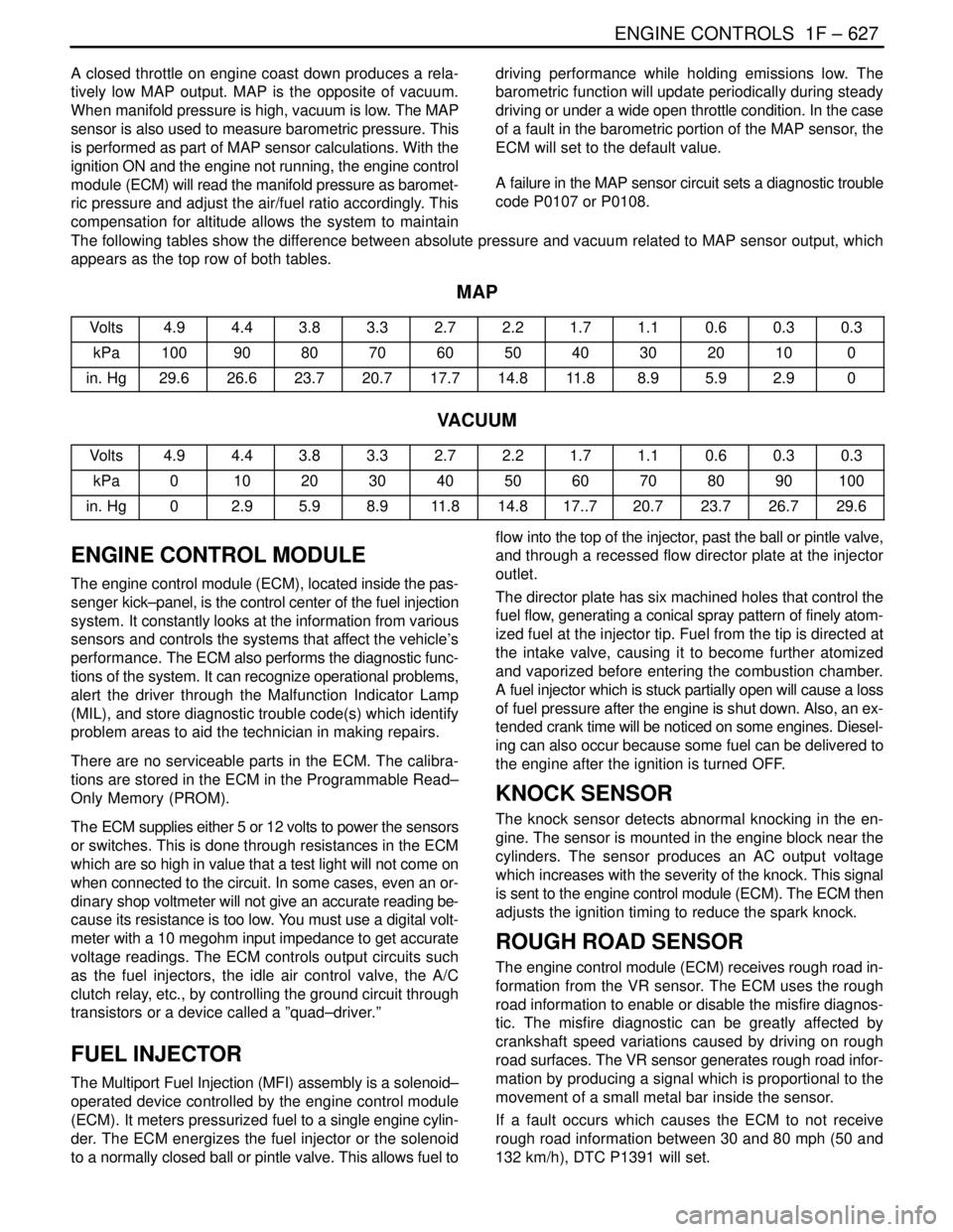
The following tables show the difference between absolute pressure and vacuum related to MAP sensor output, which
appears as the top row of both tables.
MAP
Volts4.94.43.83.32.72.21.71.10.60.30.3
kPa1009080706050403020100
in. Hg29.626.623.720.717.714.811.88.95.92.90
VACUUM
Volts4.94.43.83.32.72.21.71.10.60.30.3
kPa0102030405060708090100
in. Hg02.95.98.911.814.817..720.723.726.729.6
ENGINE CONTROL MODULE
The engine control module (ECM), located inside the pas-
senger kick–panel, is the control center of the fuel injection
system. It constantly looks at the information from various
sensors and controls the systems that affect the vehicle’s
performance. The ECM also performs the diagnostic func-
tions of the system. It can recognize operational problems,
alert the driver through the Malfunction Indicator Lamp
(MIL), and store diagnostic trouble code(s) which identify
problem areas to aid the technician in making repairs.
There are no serviceable parts in the ECM. The calibra-
tions are stored in the ECM in the Programmable Read–
Only Memory (PROM).
The ECM supplies either 5 or 12 volts to power the sensors
or switches. This is done through resistances in the ECM
which are so high in value that a test light will not come on
when connected to the circuit. In some cases, even an or-
dinary shop voltmeter will not give an accurate reading be-
cause its resistance is too low. You must use a digital volt-
meter with a 10 megohm input impedance to get accurate
voltage readings. The ECM controls output circuits such
as the fuel injectors, the idle air control valve, the A/C
clutch relay, etc., by controlling the ground circuit through
transistors or a device called a ”quad–driver.”
FUEL INJECTOR
The Multiport Fuel Injection (MFI) assembly is a solenoid–
operated device controlled by the engine control module
(ECM). It meters pressurized fuel to a single engine cylin-
der. The ECM energizes the fuel injector or the solenoid
to a normally closed ball or pintle valve. This allows fuel toflow into the top of the injector, past the ball or pintle valve,
and through a recessed flow director plate at the injector
outlet.
The director plate has six machined holes that control the
fuel flow, generating a conical spray pattern of finely atom-
ized fuel at the injector tip. Fuel from the tip is directed at
the intake valve, causing it to become further atomized
and vaporized before entering the combustion chamber.
A fuel injector which is stuck partially open will cause a loss
of fuel pressure after the engine is shut down. Also, an ex-
tended crank time will be noticed on some engines. Diesel-
ing can also occur because some fuel can be delivered to
the engine after the ignition is turned OFF.
KNOCK SENSOR
The knock sensor detects abnormal knocking in the en-
gine. The sensor is mounted in the engine block near the
cylinders. The sensor produces an AC output voltage
which increases with the severity of the knock. This signal
is sent to the engine control module (ECM). The ECM then
adjusts the ignition timing to reduce the spark knock.
ROUGH ROAD SENSOR
The engine control module (ECM) receives rough road in-
formation from the VR sensor. The ECM uses the rough
road information to enable or disable the misfire diagnos-
tic. The misfire diagnostic can be greatly affected by
crankshaft speed variations caused by driving on rough
road surfaces. The VR sensor generates rough road infor-
mation by producing a signal which is proportional to the
movement of a small metal bar inside the sensor.
If a fault occurs which causes the ECM to not receive
rough road information between 30 and 80 mph (50 and
132 km/h), DTC P1391 will set.
Page 874 of 2643
1F – 628IENGINE CONTROLS
DAEWOO V–121 BL4
STRATEGY – BASED DIAGNOSTICS
Strategy–Based Diagnostics
The strategy–based diagnostic is a uniform approach to
repair all Electrical/Electronic (E/E) systems. The diag-
nostic flow can always be used to resolve an E/E system
problem and is a starting point when repairs are neces-
sary. The following steps will instruct the technician on
how to proceed with a diagnosis:
S Verify the customer complaint. To verify the cus-
tomer complaint, the technician should know the
normal operation of the system.
S Perform preliminary checks as follows:
S Conduct a thorough visual inspection.
S Review the service history.
S Detect unusual sounds or odors.
S Gather Diagnostic Trouble Code (DTC) informa-
tion to achieve an effective repair.
S Check bulletins and other service information. This
includes videos, newsletters, etc.
S Refer to service information (manual) system
check(s).
S Refer to service diagnostics.
No Trouble Found
This condition exists when the vehicle is found to operate
normally. The condition described by the customer may be
normal. Verify the customer complaint against another ve-
hicle that is operating normally. The condition may be in-
termittent. Verify the complaint under the conditions de-
scribed by the customer before releasing the vehicle.
Re–examine the complaint.
When the complaint cannot be successfully found or iso-
lated, a re–evaluation is necessary. The complaint should
be re–verified and could be intermittent as defined in ”In-
termittents,” or could be normal.
After isolating the cause, the repairs should be made. Vali-
date for proper operation and verify that the symptom has
been corrected. This may involve road testing or other
methods to verify that the complaint has been resolved un-
der the following conditions:
S Conditions noted by the customer.
S If a DTC was diagnosed, verify a repair by duplicat-
ing conditions present when the DTC was set as
noted in the Failure Records or Freeze Frame data.
Verifying Vehicle Repair
Verification of the vehicle repair will be more comprehen-
sive for vehicles with On–Board Diagnostic (EOBD) sys-
tem diagnostics. Following a repair, the technician should
perform these steps:
Important : Follow the steps below when you verify re-
pairs on EOBD systems. Failure to follow these steps
could result in unnecessary repairs.S Review and record the Failure Records and the
Freeze Frame data for the DTC which has been
diagnosed (Freeze Fame data will only be stored
for an A or B type diagnostic and only if the MIL
has been requested).
S Clear the DTC(s).
S Operate the vehicle within conditions noted in the
Failure Records and Freeze Frame data.
S Monitor the DTC status information for the specific
DTC which has been diagnosed until the diagnostic
test associated with that DTC runs.
EOBD SERVICEABILITY ISSUES
Based on the knowledge gained from On–Board Diagnos-
tic (EOBD) experience in the 1994 and 1995 model years,
this list of non–vehicle faults that could affect the perfor-
mance of the EOBD system has been compiled. These
non–vehicle faults vary from environmental conditions to
the quality of fuel used. With the introduction of EOBD
diagnostics across the entire passenger car and light–duty
truck market in 1996, illumination of the MIL due to a non–
vehicle fault could lead to misdiagnosis of the vehicle, in-
creased warranty expense and customer dissatisfaction.
The following list of non–vehicle faults does not include ev-
ery possible fault and may not apply equally to all product
lines.
Fuel Quality
Fuel quality is not a new issue for the automotive industry,
but its potential for turning on the Malfunction Indicator
Lamp (MIL) with EOBD systems is new.
Fuel additives such as ”dry gas” and ”octane enhancers”
may affect the performance of the fuel. If this results in an
incomplete combustion or a partial burn, it will set DTC
P0300. The Reed Vapor Pressure of the fuel can also
create problems in the fuel system, especially during the
spring and fall months when severe ambient temperature
swings occur. A high Reed Vapor Pressure could show up
as a Fuel Trim DTC due to excessive canister loading.
High vapor pressures generated in the fuel tank can also
affect the Evaporative Emission diagnostic as well.
Using fuel with the wrong octane rating for your vehicle
may cause driveability problems. Many of the major fuel
companies advertise that using ”premium” gasoline will
improve the performance of your vehicle. Most premium
fuels use alcohol to increase the octane rating of the fuel.
Although alcohol–enhanced fuels may raise the octane
rating, the fuel’s ability to turn into vapor in cold tempera-
tures deteriorates. This may affect the starting ability and
cold driveability of the engine.
Low fuel levels can lead to fuel starvation, lean engine op-
eration, and eventually engine misfire.
Non–OEM Parts
All of the EOBD diagnostics have been calibrated to run
with Original Equipment Manufacturer (OEM) parts.
Something as simple as a high–performance exhaust sys-
tem that affects exhaust system back pressure could po-
Page 876 of 2643
1F – 630IENGINE CONTROLS
DAEWOO V–121 BL4
COMPREHENSIVE COMPONENT
MONITOR DIAGNOSTIC OPERATION
Comprehensive component monitoring diagnostics are
required to monitor emissions–related input and output
powertrain components.
Input Components
Input components are monitored for circuit continuity and
out–of–range values. This includes rationality checking.
Rationality checking refers to indicating a fault when the
signal from a sensor does not seem reasonable, i.e.
Throttle Position (TP) sensor that indicates high throttle
position at low engine loads or Manifold Absolute Pressure
(MAP) voltage. Input components may include, but are not
limited to, the following sensors:
S Vehicle Speed Sensor (VSS).
S Crankshaft Position (CKP) sensor.
S Throttle Position (TP) sensor.
S Engine Coolant Temperature (ECT) sensor.
S Camshaft Position (CMP) sensor.
S Manifold Absolute Pressure (MAP) sensor.
In addition to the circuit continuity and rationality check,
the ECT sensor is monitored for its ability to achieve a
steady state temperature to enable closed loop fuel con-
trol.
Output Components
Output components are diagnosed for proper response to
control module commands. Components where functional
monitoring is not feasible will be monitored for circuit conti-
nuity and out–of–range values if applicable. Output com-
ponents to be monitored include, but are not limited to the
following circuit:
S Idle Air Control (IAC) Motor.
S Control module controlled EVAP Canister Purge
Valve.
S A/C relays.
S Cooling fan relay.
S VSS output.
S MIL control.
Refer to ”Engine Control Module” and Sensors in this sec-
tion.
Passive and Active Diagnostic Tests
A passive test is a diagnostic test which simply monitors
a vehicle system or component. Conversely, an active
test, actually takes some sort of action when performing
diagnostic functions, often in response to a failed passive
test. For example, the Exhaust Gas Recirculation (EGR)
diagnostic active test will force the EGR valve open during
closed throttle deceleration and/or force the EGR valve
closed during a steady state. Either action should result in
a change in manifold pressure.
Intrusive Diagnostic Tests
This is any on–board test run by the Diagnostic Manage-
ment System which may have an effect on vehicle perfor-
mance or emission levels.
Warm–Up Cycle
A warm–up cycle means that engine temperature must
reach aminimum of 160°F (70°C) and rise at least 72°F
(22°C) over the course of a trip.
Freeze Frame
Freeze Frame is an element of the Diagnostic Manage-
ment System which stores various vehicle information at
the moment an emissions–related fault is stored in
memory and when the Malfunction Indicator Lamp (MIL)
is commanded on. These data can help to identify the
cause of a fault.
Failure Records
Failure Records data is an enhancement of the EOBD
Freeze Frame feature. Failure Records store the same ve-
hicle information as does Freeze Frame, but it will store
that information for any fault which is stored in onboard
memory, while Freeze Frame stores information only for
emission–related faults that command the MIL on.
COMMON EOBD TERMS
Diagnostic
When used as a noun, the word diagnostic refers to any
on–board test run by the vehicle’s Diagnostic Manage-
ment System. A diagnostic is simply a test run on a system
or component to determine if the system or component is
operating according to specification. There are many diag-
nostics, shown in the following list:
S Misfire
S Front Heated Oxygen Sensor (HO2S1)
S Rear Heated Oxygen Sensor (HO2S2)
S Exhaust Gas Recirculation (EGR)
S Catalyst monitoring
Enable Criteria
The term ”enable criteria” is engineering language for the
conditions necessary for a given diagnostic test to run.
Each diagnostic has a specific list of conditions which
must be met before the diagnostic will run.
”Enable criteria” is another way of saying ”conditions re-
quired.”
The enable criteria for each diagnostic is listed on the first
page of the Diagnostic Trouble Code (DTC) description
under the heading ”Conditions for Setting the DTC.” En-
able criteria varies with each diagnostic and typically in-
cludes, but is not limited to, the following items:
S Engine speed.
S Vehicle speed
S Engine Coolant Temperature (ECT)
S Manifold Absolute Pressure (MAP)
Page 877 of 2643
ENGINE CONTROLS 1F – 631
DAEWOO V–121 BL4
S Barometric Pressure (BARO)
S Intake Air Temperature (IAT)
S Throttle Position (TP)
S High canister purge
S Fuel trim
S A/C on
Trip
Technically, a trip is a key–on run key–off cycle in which all
the enable criteria for a given diagnostic are met, allowing
the diagnostic to run. Unfortunately, this concept is not
quite that simple. A trip is official when all the enable crite-
ria for a given diagnostic are met. But because the enable
criteria vary from one diagnostic to another, the definition
of trip varies as well. Some diagnostics are run when the
vehicle is at operating temperature, some when the ve-
hicle first starts up; some require that the vehicle be cruis-
ing at a steady highway speed, some run only when the
vehicle is at idle; some diagnostics function with the
Torque Converter Clutch (TCC) disabled. Some run only
immediately following a cold engine startup.
A trip then, is defined as a key–on run key–off cycle in
which the vehicle was operated in such a way as to satisfy
the enables criteria for a given diagnostic, and this diag-
nostic will consider this cycle to be one trip. However,
another diagnostic with a different set of enable criteria
(which were not met) during this driving event, would not
consider it a trip. No trip will occur for that particular diag-
nostic until the vehicle is driven in such a way as to meet
all the enable criteria
Diagnostic Information
The diagnostic charts and functional checks are designed
to locate a faulty circuit or component through a process
of logical decisions. The charts are prepared with the re-
quirement that the vehicle functioned correctly at the time
of assembly and that there are not multiple faults present.
There is a continuous self–diagnosis on certain control
functions. This diagnostic capability is complimented by
the diagnostic procedures contained in this manual. The
language of communicating the source of the malfunction
is a system of diagnostic trouble codes. When a malfunc-
tion is detected by the control module, a diagnostic trouble
code is set and the Malfunction Indicator Lamp (MIL) is illu-
minated.
Malfunction Indicator Lamp (MIL)
The Malfunction Indicator Lamp (MIL) is required by On–
Board Diagnostics (EOBD) that it illuminates under a strict
set of guide lines.
Basically, the MIL is turned on when the engine control
module (ECM) detects a DTC that will impact the vehicle
emissions.The MIL is under the control of the Diagnostic Executive.
The MIL will be turned on if an emissions–related diagnos-
tic test indicates a malfunction has occurred. It will stay on
until the system or component passes the same test, for
three consecutive trips, with no emissions related faults.
Extinguishing the MIL
When the MIL is on, the Diagnostic Executive will turn off
the MIL after three consecutive trips that a ”test passed”
has been reported for the diagnostic test that originally
caused the MIL to illuminate. Although the MIL has been
turned off, the DTC will remain in the ECM memory (both
Freeze Frame and Failure Records) until forty (40) warm–
up cycles after no faults have been completed.
If the MIL was set by either a fuel trim or misfire–related
DTC, additional requirements must be met. In addition to
the requirements stated in the previous paragraph, these
requirements are as follows:
S The diagnostic tests that are passed must occur
with 375 rpm of the rpm data stored at the time the
last test failed.
S Plus or minus ten percent of the engine load that
was stored at the time the last test failed. Similar
engine temperature conditions (warmed up or
warming up) as those stored at the time the last
test failed.
Meeting these requirements ensures that the fault which
turned on the MIL has been corrected.
The MIL is on the instrument panel and has the following
functions:
S It informs the driver that a fault that affects vehicle
emission levels has occurred and that the vehicle
should be taken for service as soon as possible.
S As a system check, the MIL will come on with the
key ON and the engine not running. When the en-
gine is started, the MIL will turn OFF.
S When the MIL remains ON while the engine is run-
ning, or when a malfunction is suspected due to a
driveability or emissions problem, an EOBD System
Check must be performed. The procedures for
these checks are given in EOBD System Check.
These checks will expose faults which may not be
detected if other diagnostics are performed first.
Data Link Connector (DLC)
The provision for communicating with the control module
is the Data Link Connector (DLC). The DLC is used to con-
nect to a scan tool. Some common uses of the scan tool
are listed below:
S Identifying stored DTCs.
S Clearing DTCs.
S Performing output control tests.
S Reading serial data.
Page 1163 of 2643
ELECTRICAL WIRING DIAGRAMSW5–3
4. ECM (ENGINE CONTROL MODULE) : SIRIUS D4 5–34. . . . . . . . . . . . . . . . . . . . . . . . . . . . . . . . . . . . . . . . . . . . . . . . . .
1) BATTERY POWER SUPPLY, GROUND, EI SYSTEM & CKP SENSOR CIRCUIT 5–34. . . . . . . . . . . . . . . . . . . . .
2) FUEL PUMP, INJECTOR, FUEL CONNECTOR & CMP SENSOR CIRCUIT 5–36. . . . . . . . . . . . . . . . . . . . . . . . .
3) MTIA, SENSOR(ECT, KNOCK, IAT, MAP, ACP & HO2S) & POWER STEERING PRESSURE SWITCH
CIRCUIT : EOBD5–38 . . . . . . . . . . . . . . . . . . . . . . . . . . . . . . . . . . . . . . . . . . . . . . . . . . . . . . . . . . . . . . . . . . . . . . . . . . . . . . . .
4) MTIA, SENSOR(ECT, KNOCK, IAT, MAP, ACP & O2) & POWER STEERING PRESSURE SWITCH
CIRCUIT : NON EOBD5–40 . . . . . . . . . . . . . . . . . . . . . . . . . . . . . . . . . . . . . . . . . . . . . . . . . . . . . . . . . . . . . . . . . . . . . . . . . . .
5) EEGR VALVE, VR SENSOR, CLUSTER & FUEL PUMP CIRCUIT : EOBD 5–42. . . . . . . . . . . . . . . . . . . . . . . . . .
6) EGR VALVE, CLUSTER & FUEL PUMP CIRCUIT: NON EOBD 5–44. . . . . . . . . . . . . . . . . . . . . . . . . . . . . . . . . . . .
7) EVAP CANISTER PURGE SOLENOID, VGIS, CLUSTER, VSS, TCM & RON SWITCH CIRCUIT 5–46. . . . . . .
8) DLC, MIL LAMP & IMMOBILIZER CONTROL CIRCUIT 5–48. . . . . . . . . . . . . . . . . . . . . . . . . . . . . . . . . . . . . . . . . . .
5. TCM (TRANSMISSION CONTROL MODULE) : MR–140/HV–240 5–50. . . . . . . . . . . . . . . . . . . . . . . . . . . . . . . . . . . . .
1) POWER SUPPLY, GROUND, PNP SWITCH, BRAKE SWITCH & SOLENOID VALVE CIRCUIT 5–50. . . . . . . .
2) SENSOR(INPUT SPEED,OUTPUT SPEED, TRANSMISSION FLUID TEMP.), CLUSTER, DLC, ECM &
HOLD MODE SWITCH CIRCUIT5–52 . . . . . . . . . . . . . . . . . . . . . . . . . . . . . . . . . . . . . . . . . . . . . . . . . . . . . . . . . . . . . . . . . .
3) PNP SWITCH & CLUSTER CIRCUIT 5–54. . . . . . . . . . . . . . . . . . . . . . . . . . . . . . . . . . . . . . . . . . . . . . . . . . . . . . . . . . .
6. TCM (TRANSMISSION CONTROL MODULE) : SIRIUS D4 5–56. . . . . . . . . . . . . . . . . . . . . . . . . . . . . . . . . . . . . . . . . .
1) POWER SUPPLY, GROUND, PNP SWITCH, CLUSTER & ECM CIRCUIT : NOTCH BACK 5–56. . . . . . . . . . . .
2) POWER SUPPLY, GROUND, PNP SWITCH, CLUSTER & ECM CIRCUIT : HATCH BACK 5–58. . . . . . . . . . . .
3) BRAKE SWITCH, BTSI SOLENOID, ISS SENSOR & TRANSAXLE CIRCUIT 5–60. . . . . . . . . . . . . . . . . . . . . . . .
4) HOLD MODE SWITCH, VSS & DLC CIRCUIT 5–62. . . . . . . . . . . . . . . . . . . . . . . . . . . . . . . . . . . . . . . . . . . . . . . . . . .
7. AIR CONDITIONER5–64 . . . . . . . . . . . . . . . . . . . . . . . . . . . . . . . . . . . . . . . . . . . . . . . . . . . . . . . . . . . . . . . . . . . . . . . . . . . . .
1) AIR CONDITIONER CONTROL SWITCH, BLOWER MOTOR RESISTER & BLOWER MOTOR
CIRCUIT5–64 . . . . . . . . . . . . . . . . . . . . . . . . . . . . . . . . . . . . . . . . . . . . . . . . . . . . . . . . . . . . . . . . . . . . . . . . . . . . . . . . . . . . . . . .
2) AIR CONDITIONER CONTROL, INTAKE MOTOR SWITCH & AIR CONDITIONER COMPRESSOR
CIRCUIT5–66 . . . . . . . . . . . . . . . . . . . . . . . . . . . . . . . . . . . . . . . . . . . . . . . . . . . . . . . . . . . . . . . . . . . . . . . . . . . . . . . . . . . . . . . .
Page 1166 of 2643

5–6WELECTRICAL WIRING DIAGRAMS
20. REAR WINDOW DEFROSTER & OSRV MIRROR HEATING SYSTEM CIRCUIT 5–144. . . . . . . . . . . . . . . . . . . . . . .
21. ELECTRIC OSRV (OUTSIDE REAR VIEW) MIRROR CIRCUIT 5–146. . . . . . . . . . . . . . . . . . . . . . . . . . . . . . . . . . . . . .
22. FOLDING MIRROR UNIT CIRCUIT 5–148. . . . . . . . . . . . . . . . . . . . . . . . . . . . . . . . . . . . . . . . . . . . . . . . . . . . . . . . . . . . . .
23. POWER WINDOW CIRCUIT5–150 . . . . . . . . . . . . . . . . . . . . . . . . . . . . . . . . . . . . . . . . . . . . . . . . . . . . . . . . . . . . . . . . . . . . .
1) ONLY FRONT POWER WINDOW CIRCUIT 5–150. . . . . . . . . . . . . . . . . . . . . . . . . . . . . . . . . . . . . . . . . . . . . . . . . . . .
2) FRONT & REAR POWER WINDOW CIRCUIT 5–152. . . . . . . . . . . . . . . . . . . . . . . . . . . . . . . . . . . . . . . . . . . . . . . . . .
24. CENTRAL DOOR LOCKING SYSTEM CIRCUIT 5–154. . . . . . . . . . . . . . . . . . . . . . . . . . . . . . . . . . . . . . . . . . . . . . . . . . .
1) NOTCH BACK5–154 . . . . . . . . . . . . . . . . . . . . . . . . . . . . . . . . . . . . . . . . . . . . . . . . . . . . . . . . . . . . . . . . . . . . . . . . . . . . . .
2) HATCH BACK5–156 . . . . . . . . . . . . . . . . . . . . . . . . . . . . . . . . . . . . . . . . . . . . . . . . . . . . . . . . . . . . . . . . . . . . . . . . . . . . . .
25. CLUSTER5–158 . . . . . . . . . . . . . . . . . . . . . . . . . . . . . . . . . . . . . . . . . . . . . . . . . . . . . . . . . . . . . . . . . . . . . . . . . . . . . . . . . . . . .
1) TEMPERATURE GAUGE, TACHOMETER, FUEL GAUGE, ODDOMETER, SPEEDOMETER & FUEL
WARNING LAMP CIRCUIT : MR–140/HV–240 5–158. . . . . . . . . . . . . . . . . . . . . . . . . . . . . . . . . . . . . . . . . . . . . . . . . . . . .
2) TEMPERATURE GAUGE, TACHOMETER, FUEL GAUGE, ODDOMETER, SPEEDOMETER & FUEL
WARNING LAMP CIRCUIT : SIRIUS D4 5–160. . . . . . . . . . . . . . . . . . . . . . . . . . . . . . . . . . . . . . . . . . . . . . . . . . . . . . . . . . .
3) WARNING(MIL, ABS, TCS, PARKING BRAKE & CHARGING) LAMP CIRCUIT 5–162. . . . . . . . . . . . . . . . . . . . .
4) WARNING(SSPS, AIR BAG, OIL PRESSURE & SEAT BELT) LAMP & HOLD MODE CIRCUIT 5–164. . . . . . .
5) INDICATOR LAMP (FRONT & REAR FOG) & DOOR OPENING WARNING LAMP CIRCUIT 5–166. . . . . . . . .
6) INDICATOR LAMP (TURN SIGNAL, HIGH BEAM & HAZARD) & ILLUMINATION LAMP CIRCUIT 5–168. . . . .
26. AUDIO CIRCUIT5–170 . . . . . . . . . . . . . . . . . . . . . . . . . . . . . . . . . . . . . . . . . . . . . . . . . . . . . . . . . . . . . . . . . . . . . . . . . . . . . . .
1) NOTCH BACK5–170 . . . . . . . . . . . . . . . . . . . . . . . . . . . . . . . . . . . . . . . . . . . . . . . . . . . . . . . . . . . . . . . . . . . . . . . . . . . . . .
2) HATCH BACK5–172 . . . . . . . . . . . . . . . . . . . . . . . . . . . . . . . . . . . . . . . . . . . . . . . . . . . . . . . . . . . . . . . . . . . . . . . . . . . . . .
27. ABS (ANTILOCK BRAKE SYSTEM) 5–174. . . . . . . . . . . . . . . . . . . . . . . . . . . . . . . . . . . . . . . . . . . . . . . . . . . . . . . . . . . . .
1) POWER SUPPLY, WHEEL SPEED SENSOR & BRAKE SWITCH CIRCUIT 5–174. . . . . . . . . . . . . . . . . . . . . . . .
2) OIL FEEDING CONNECTOR, WARNING(ABS, TCS & BRAKE) LAMP & DLC CIRCUIT 5–176. . . . . . . . . . . . .
28. AIR BAG (SDM: SENSING & DIAGNOSTIC MODULE) CIRCUIT 5–178. . . . . . . . . . . . . . . . . . . . . . . . . . . . . . . . . . . .
Page 1399 of 2643
5A1 – 50IZF 4 HP 16 AUTOMATIC TRANSAXLE
DAEWOO V–121 BL4
TCC shudder should only occur during the APPLY and/or
RELEASE of the Lock up clutch.
While TCC Is Applying Or Releasing
If the shudder occurs while TCC is applying, the problem
can be within the transaxle or torque converter.
Something is not allowing the clutch to become fully en-
gaged, not allowing clutch to release, or is trying to release
and apply the clutch at the same time. This could be
caused by leaking turbine shaft seals, a restricted release
orifice, a distorted clutch or housing surface due to long
converter bolts, or defective friction material on the TCC
plate.
Shudder Occurs After TCC Has Applied :
In this case, most of the time there is nothing wrong with
the transaxle! As mentioned above, once the TCC has
been applied, it is very unlikely that will slip. Engine prob-
lems may go unnoticed under light throttle and load, but
become noticeable after TCC apply when going up a hill
or accelerating, due to the mechanical coupling between
engine and transaxle.
Important : Once TCC is applied there is no torque con-
verter assistance. Engine or driveline vibrations could be
unnoticeable before TCC engagement.
Inspect the following components to avoid misdiagnosis of
TCC shudder and possibly disassembling a transaxle and/
or replacing a torque converter unnecessarily :
S Spark plugs – Inspect for cracks, high resistance or
broken insulator.
S Plug wires – Lock in each end, if there is red dust
(ozone) or black substance (carbon) present, then
the wires are bad. Also look for a white discolor-
ation of the wire indicating arcing during hard accel-
eration.
S Distributor cap and rotor – look for broken or un–
crimped parts.
S Coil – look for black on bottom indication arcing
while engine is misfiring.
S Fuel injector – filter may be plugged.
S Vacuum leak – engine won’t get correct amount of
fuel. May run rich or lean depending on where the
leak is.S EGR valve – valve may let it too much unburnable
exhaust gas and cause engine to run lean.
S MAP sensor – like vacuum leak, engine won’t get
correct amount of fuel for proper engine operation.
S Carbon on intake valves – restricts proper flow or
air/fuel mixture into cylinders.
S Flat cam – valves don’t open enough to let proper
fuel/air mixture into cylinders.
S Oxygen sensor – may command engine too rich or
too lean for too long.
S Fuel pressure – may be too low.
S Engine mounts – vibration of mounts can be multi-
plied by TCC engagement.
S Axle joints – checks for vibration.
S TPS – TCC apply and release depends on the TPS
in many engines. If TPS is out of specification, TCC
may remain applied during initial engine starting.
S Cylinder balance – bad piston rings or poorly seal-
ing valves can cause low power in a cylinder.
S Fuel contamination – causes poor engine perfor-
mance.
TCM INITIALIZATION PROCEDURE
When one or more operations such as shown below are
performed, all learned contents which are stored in TCM
memory should be erased after the operations.
S When A/T H/W is replaced in a vehicle,
S When a used TCU is installed in other vehicle,
S When a vehicle condition is unstable (engine RPM
flare, TPS toggling and so on; at this kind of unsta-
ble conditions, mis–adaptation might be done).
1. Connect the Scan 100 with a DLC connector in a
vehicle.
2. Turn ignition switch ON.
3. Turn the power on for the Scan 100.
4. Follow the ”TCM LEARNED INITIALIZE” procedure
on the Scan 100 menu.
Notice : Before pushing ”Yes” Button for TCM initialization
on the Scan 100 screen, make sure that the condition is
as follows:
Condition :
1. Engine idle.
2. Select lever set ”P” range.
Page 1581 of 2643
5A1 – 232IZF 4 HP 16 AUTOMATIC TRANSAXLE
DAEWOO V–121 BL4
GENERAL DESCRIPTION
AND SYSTEM OPERATION
The ZF 4HP 16 automatic transaxle consists primarily of
the following components.
Mechanical
S Torque converter with TCC
S Drive link assembly
S Two multiple disk clutch assemblies : Clutch B,E
S Three multiple brake assemblies : Brake C,D,F
S Lock–up clutch valve
S Two planetary gear sets
S One oil pump
S Final drive and differential assembly
Electronic
S Two shift solenoid valve(sol.1,2)
S Four pressure control solenoid valve(EDS)
S Two speed sensors : A/T ISS and A/T OSS
S Fluid temperature sensor
S Automatic transaxle control module(TCM)
S Wiring harness assembly
MECHANICAL COMPONENTS
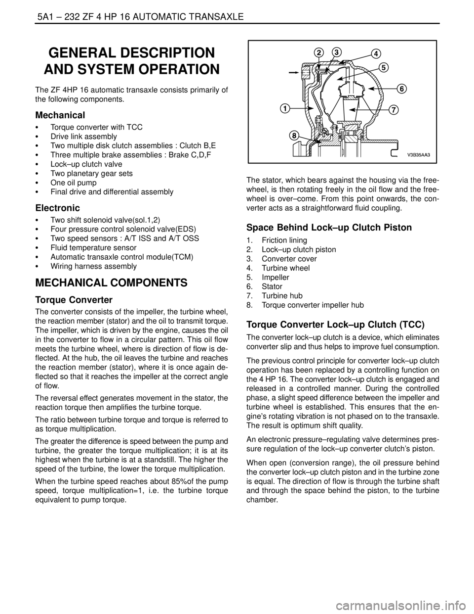
Torque Converter
The converter consists of the impeller, the turbine wheel,
the reaction member (stator) and the oil to transmit torque.
The impeller, which is driven by the engine, causes the oil
in the converter to flow in a circular pattern. This oil flow
meets the turbine wheel, where is direction of flow is de-
flected. At the hub, the oil leaves the turbine and reaches
the reaction member (stator), where it is once again de-
flected so that it reaches the impeller at the correct angle
of flow.
The reversal effect generates movement in the stator, the
reaction torque then amplifies the turbine torque.
The ratio between turbine torque and torque is referred to
as torque multiplication.
The greater the difference is speed between the pump and
turbine, the greater the torque multiplication; it is at its
highest when the turbine is at a standstill. The higher the
speed of the turbine, the lower the torque multiplication.
When the turbine speed reaches about 85%of the pump
speed, torque multiplication=1, i.e. the turbine torque
equivalent to pump torque.
The stator, which bears against the housing via the free-
wheel, is then rotating freely in the oil flow and the free-
wheel is over–come. From this point onwards, the con-
verter acts as a straightforward fluid coupling.
Space Behind Lock–up Clutch Piston
1. Friction lining
2. Lock–up clutch piston
3. Converter cover
4. Turbine wheel
5. Impeller
6. Stator
7. Turbine hub
8. Torque converter impeller hub
Torque Converter Lock–up Clutch (TCC)
The converter lock–up clutch is a device, which eliminates
converter slip and thus helps to improve fuel consumption.
The previous control principle for converter lock–up clutch
operation has been replaced by a controlling function on
the 4 HP 16. The converter lock–up clutch is engaged and
released in a controlled manner. During the controlled
phase, a slight speed difference between the impeller and
turbine wheel is established. This ensures that the en-
gine’s rotating vibration is not phased on to the transaxle.
The result is optimum shift quality.
An electronic pressure–regulating valve determines pres-
sure regulation of the lock–up converter clutch’s piston.
When open (conversion range), the oil pressure behind
the converter lock–up clutch piston and in the turbine zone
is equal. The direction of flow is through the turbine shaft
and through the space behind the piston, to the turbine
chamber.