fuel pressure DAEWOO NUBIRA 2004 Service Manual Online
[x] Cancel search | Manufacturer: DAEWOO, Model Year: 2004, Model line: NUBIRA, Model: DAEWOO NUBIRA 2004Pages: 2643, PDF Size: 80.54 MB
Page 652 of 2643

1F – 406IENGINE CONTROLS
DAEWOO V–121 BL4
StepNo Yes Value(s) Action
111. Turn the ignition OFF.
2. Disconnect the Manifold Absolute Pressure
(MAP) sensor electrical connector.
3. Start the engine.
4. Operate the vehicle in Closed Loop while moni-
toring the Long Term Fuel Trim value.
Does the Long Term Fuel Trim value increase above
the specified value?–20%Go to Step 20Go to Step 12
12Check the IAC valve performance. Refer to ”DTC
P0506 Idle Speed RPM Lower Than Desired Idle
Speed” or ”DTC P0507 Idle Speed RPM Higher
Than Desired Idle Speed”in this section and repair
as necessary.
Is the repair complete?–Go to Step 21Go to Step 13
131. Disconnect the vacuum hose from the fuel
pressure regulator and inspect the hose for the
presence of fuel.
2. If fuel is presence in the vacuum hose, replace
the fuel pressure regulator.
Is the repair complete?–Go to Step 21Go to Step 14
141. Turn the ignition ON.
2. Slowly press the acceleration pedal.
Does the Throttle Position (TP) sensor display in-
crease steady and evenly from its minimum voltage
at closed throttle to its maximum voltage at Wide–
Open Throttle (WOT).–Go to Step 15Go to Step 19
151. Perform the Fuel System Diagnosis.
2. If the table isolate a problem, repair as needed.
Is the repair complete?–Go to Step 21Go to Step 16
161. Perform the Evaporative Emission (EVAP)
Control System Diagnosis.
2. If the table isolate a problem, repair as needed.
Is the repair complete?–Go to Step 21Go to Step 17
171. Perform the Fuel Injector Balance Test.
2. If the table isolate a problem, repair as needed.
Is the repair complete?–Go to Step 21Go to Step 18
181. Remove the Front Heated Oxygen Sensor
(HO2S1).
2. Visually/physically inspect the HO2S1 for sili-
cone contamination.
Note : this will be indicated by a powdery white de-
posit on the portion of the HO2S1 exposed to the ex-
haust stream.
1. If contamination is present on the HO2S1, find
the source and repair as needed.
Is the repair complete?–Go to Step 21Go to
”Diagnostic
Aids”
191. Check the TP sensor mounting screws.
2. If they are too loose or missing tighten or re-
place them as needed.
3. If the screws are OK, replace the TP sensor.
Is the repair complete?–Go to Step 21–
Page 668 of 2643

1F – 422IENGINE CONTROLS
DAEWOO V–121 BL4
8. Check fuel for water, alcohol, etc.
9. A basic engine problem that affects all cylinders is
the only possibility at this point. (Cam timing,
throttle body leak, restricted air flow, etc.)
11. Tests the ignition system voltage output using a
spark tester.
12. Replace any spark plugs that are worn, cracked or
fouled.
13. Checks for voltage at the ignition feed circuit.
18. Whenever the driver circuit is shorted to ground,
the light will be on steady. When the driver circuit is
shorted to voltage or open, the light will be off.19. Since voltage is supplied to the fuel injector on a
single circuit, the malfunction could only be a poor
connection or open in the fuel injector harness. An
open before the harness would result in an ”Engine
Cranks But Will Not Run” complaint.
28. Before replacing the ECM, check terminals for im-
proper mating, broken locks, or physical damage to
the wiring harness. The replacement ECM must be
reprogrammed. Refer to the latest Techline proce-
dure for ECM reprogramming.
DTC P0300 – Multiple Cylinder Misfire Detected
StepActionValue(s)YesNo
1Perform an On–Board Diagnostic (EOBD) System
Check.
Was the check performed?–Go to Step 2Go to
”On–Board
Diagnostic Sys-
tem Check”
21. Install a scan tool to the Data Link Connector
(DLC).
2. Turn the ignition ON, with the engine OFF.
3. Request Diagnostic Trouble Codes (DTCs)
Are DTCs P0201, P0202, P0203, P0204 set?–Go to applica-
ble DTCGo to Step 3
31. Perform a visual/physical inspection.
2. Make any repairs that are necessary.
Is the repair complete?–Go to Step 27Go to Step 4
4Start the engine and allow it to idle.
Are any Misfire Current counters incrementing?–Go to Step 5Go to Step 6
5Are all counters equal (within a percentage of each
other)?–Go to Step 7Go to Step 11
61. Turn the ignition ON, with the engine OFF.
2. Review the Freeze Frame data, and note the
parameters.
3. Operate the vehicle within the Freeze Frame
conditions and conditions for setting this DTC
as noted.
Are any Misfire Current counters incrementing?–Go to Step 5Go to
”Diagnostic
Aids”
71. Turn the engine OFF.
2. Install a fuel pressure gauge to the fuel rail.
3. Observe the fuel pressure with the engine run-
ning.
Is the fuel pressure within the specified value?284–325 kPa
(41–47 psi)Go to Step 8Go to
”Fuel System
Diagnosis”
8Check the fuel for contamination.
Is the fuel OK?–Go to Step 9Go to Step 10
9Check for a basic engine problem and repair as nec-
essary.
Is the repair complete?–Go to Step 27–
10Replace the contaminated fuel.
Is the repair complete?–Go to Step 27–
Page 673 of 2643

ENGINE CONTROLS 1F – 427
DAEWOO V–121 BL4
misfire. Depending on the engine load, the condi-
tions may have to be maintained for up to 20 sec-
onds. Whenever the misfire accumulators start to
increment, then misfire is present. A history misfire
counter will store the number of misfires that have
occurred until the DTC is cleared.
8. Check the fuel for water, alcohol, etc.
9. A basic engine problem that affects all cylinders is
the only possibility at this point. (Cam timing,
throttle body leak, restricted air flow, etc.)
11. Tests the ignition system voltage output using a
spark tester.
12. Replace any spark plugs that are worn, cracked or
fouled.
13. Checks for voltage at the ignition feed circuit.18. Whenever the driver circuit is shorted to ground,
the light will be on steady. When the driver circuit is
shorted to voltage or open, the light will be off.
19. Since voltage is supplied to the fuel injector on a
single circuit, the malfunction could only be a poor
connection or open in the fuel injector harness. An
open before the harness would result in an ”Engine
Cranks But Will Not Run” complaint.
28. Before replacing the ECM, check terminals for im-
proper mating, broken locks, or physical damage to
the wiring harness. The replacement ECM must be
reprogrammed. Refer to the latest Techline proce-
dure for ECM reprogramming.
DTC P0301 – Cylinder 1 Misfire
StepActionValue(s)YesNo
1Perform an On–Board Diagnostic (EOBD) System
Check.
Was the check performed?–Go to Step 2Go to
”On–Board
Diagnostic Sys-
tem Check”
21. Install a scan tool to the Data Link Connector
(DLC)
2. Turn the ignition ON, with the engine OFF.
3. Request Diagnostic Trouble Codes (DTCs)
Are DTCs P0201 or P300 set?–Go to applica-
ble DTCGo to Step 3
31. Perform a visual/physical inspection.
2. Make any repairs that are necessary.
Is the repair complete?–Go to Step 27Go to Step 4
4Start the engine and allow it to idle.
Are any Misfire Current counters incrementing?–Go to Step 5Go to Step 6
5Are all counters equal (within a percentage of each
other)?–Go to Step 7Go to Step 11
61. Turn the ignition ON, with the engine OFF.
2. Review the Freeze Frame data, and note the
parameters.
3. Operate the vehicle within the Freeze Frame
conditions and conditions for setting this DTC
as noted.
Are any Misfire Current counters incrementing?–Go to Step 5Go to
”Diagnostic
Aids”
71. Turn the engine OFF.
2. Install a fuel pressure gauge to the fuel rail.
3. Observe the fuel pressure with the engine run-
ning.
Is the fuel pressure within the specified value?284–325 kPa
(41–47 psi)Go to Step 8Go to
”Fuel System
Diagnosis”
8Check the fuel for contamination.
Is the fuel OK?–Go to Step 9Go to Step 10
9Check for a basic engine problem and repair as nec-
essary.
Is the repair complete?–Go to Step 27–
10Replace the contaminated fuel.
Is the repair complete?–Go to Step 27–
Page 678 of 2643

1F – 432IENGINE CONTROLS
DAEWOO V–121 BL4
8. Check the fuel for water, alcohol, etc.
9. A basic engine problem that affects all cylinders is
the only possibility at this point. (Cam timing,
throttle body leak, restricted air flow, etc.)
11. Tests the ignition system voltage output using a
spark tester.
12. Replace any spark plugs that are worn, cracked or
fouled.
13. Checks for voltage at the ignition feed circuit.
18. Whenever the driver circuit is shorted to ground,
the light will be on steady. When the driver circuit is
shorted to voltage or open, the light will be off.19. Since voltage is supplied to the fuel injector on a
single circuit, the malfunction could only be a poor
connection or open in the fuel injector harness. An
open before the harness would result in an ”Engine
Cranks But Will Not Run” complaint.
28. Before replacing the ECM, check terminals for im-
proper mating, broken locks, or physical damage to
the wiring harness. The replacement ECM must be
programmed. Refer to the latest Techline procedure
for ECM reprogramming.
DTC P0302 – Cylinder 2 Misfire
StepActionValue(s)YesNo
1Perform an On–Board Diagnostic (EOBD) System
Check.
Was the check complete?–Go to Step 2Go to
”On–Board
Diagnostic Sys-
tem Check”
21. Install a scan tool to the Data Link Connector
(DLC).
2. Turn the ignition ON, with the engine OFF.
3. Request Diagnostic Trouble Codes (DTCs)
Are DTCs P0202 or P300 set?–Go to applica-
ble DTCGo to Step 3
31. Perform a visual/physical inspection.
2. Make any repairs that are necessary.
Is the repair complete?–Go to Step 27Go to Step 4
4Start the engine and allow it to idle.
Are any Misfire Current counters incrementing?–Go to Step 5Go to Step 6
5Are all counters equal (within a percentage of each
other)?–Go to Step 7Go to Step 11
61. Turn the ignition ON, with the engine OFF.
2. Review the Freeze Frame data, and note the
parameters.
3. Operate the vehicle within the Freeze Frame
conditions and conditions for setting this DTC
as noted.
Are any Misfire Current counters incrementing?–Go to Step 5Go to
”Diagnostic
Aids”
71. Turn the engine OFF.
2. Install a fuel pressure gauge to the fuel rail.
3. Observe the fuel pressure with the engine run-
ning.
Is the fuel pressure within the specified value?284–325 kPa
(41–47 psi)Go to Step 8Go to
”Fuel System
Diagnosis”
8Check the fuel for contamination.
Is the fuel OK?–Go to Step 9Go to Step 10
9Check for a basic engine problem and repair as nec-
essary.
Is the repair complete?–Go to Step 27–
10Replace the contaminated fuel.
Is the repair complete?–Go to Step 27–
Page 683 of 2643
ENGINE CONTROLS 1F – 437
DAEWOO V–121 BL4
8. Check the fuel for water, alcohol, etc.
9. A basic engine problem that affects all cylinders is
the only possibility at this point. (Cam timing,
throttle body leak, restricted air flow, etc.)
11. Tests the ignition system voltage output using a
spark tester.
12. Replace any spark plugs that are worn, cracked or
fouled.
13. Checks for voltage at the ignition feed circuit.
18. Whenever the driver circuit is shorted to ground,
the light will be on steady. When the driver circuit is
shorted to voltage or open, the light will be off.19. Since voltage is supplied to the fuel injector on a
single circuit, the malfunction could only be a poor
connection or open in the fuel injector harness. An
open before the harness would result in an ”Engine
Cranks But Will Not Run” complaint.
28. Before replacing the ECM, check terminals for im-
proper mating, broken locks, or physical damage to
the wiring harness. The replacement ECM must be
programmed. Refer to the latest Techline procedure
for ECM reprogramming.
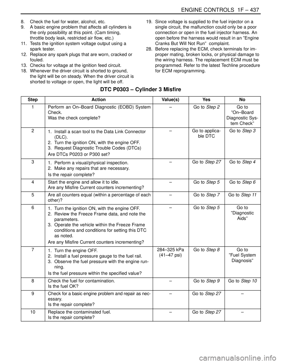
DTC P0303 – Cylinder 3 Misfire
StepActionValue(s)YesNo
1Perform an On–Board Diagnostic (EOBD) System
Check.
Was the check complete?–Go to Step 2Go to
”On–Board
Diagnostic Sys-
tem Check”
21. Install a scan tool to the Data Link Connector
(DLC).
2. Turn the ignition ON, with the engine OFF.
3. Request Diagnostic Trouble Codes (DTCs)
Are DTCs P0203 or P300 set?–Go to applica-
ble DTCGo to Step 3
31. Perform a visual/physical inspection.
2. Make any repairs that are necessary.
Is the repair complete?–Go to Step 27Go to Step 4
4Start the engine and allow it to idle.
Are any Misfire Current counters incrementing?–Go to Step 5Go to Step 6
5Are all counters equal (within a percentage of each
other)?–Go to Step 7Go to Step 11
61. Turn the ignition ON, with the engine OFF.
2. Review the Freeze Frame data, and note the
parameters.
3. Operate the vehicle within the Freeze Frame
conditions and conditions for setting this DTC
as noted.
Are any Misfire Current counters incrementing?–Go to Step 5Go to
”Diagnostic
Aids”
71. Turn the engine OFF.
2. Install a fuel pressure gauge to the fuel rail.
3. Observe the fuel pressure with the engine run-
ning.
Is the fuel pressure within the specified value?284–325 kPa
(41–47 psi)Go to Step 8Go to
”Fuel System
Diagnosis”
8Check the fuel for contamination.
Is the fuel OK?–Go to Step 9Go to Step 10
9Check for a basic engine problem and repair as nec-
essary.
Is the repair complete?–Go to Step 27–
10Replace the contaminated fuel.
Is the repair complete?–Go to Step 27–
Page 688 of 2643
1F – 442IENGINE CONTROLS
DAEWOO V–121 BL4
8. Check the fuel for water, alcohol, etc.
9. A basic engine problem that affects all cylinders is
the only possibility at this point. (Cam timing,
throttle body leak, restricted air flow, etc.)
11. Tests the ignition system voltage output using a
spark tester.
12. Replace any spark plugs that are worn, cracked or
fouled.
13. Checks for voltage at the ignition feed circuit.
18. Whenever the driver circuit is shorted to ground,
the light will be on steady. When the driver circuit is
shorted to voltage or open, the light will be off.19. Since voltage is supplied to the fuel injector on a
single circuit, the malfunction could only be a poor
connection or open in the fuel injector harness. An
open before the harness would result in an ”Engine
Cranks But Will Not Run” complaint.
28. Before replacing the ECM, check terminals for im-
proper mating, broken locks, or physical damage to
the wiring harness. The replacement ECM must be
programmed. Refer to the latest Techline procedure
for ECM reprogramming.
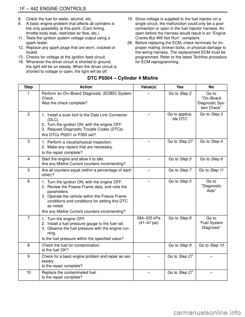
DTC P0304 – Cylinder 4 Misfire
StepActionValue(s)YesNo
1Perform an On–Board Diagnostic (EOBD) System
Check.
Was the check complete?–Go to Step 2Go to
”On–Board
Diagnostic Sys-
tem Check”
21. Install a scan tool to the Data Link Connector
(DLC).
2. Turn the ignition ON, with the engine OFF.
3. Request Diagnostic Trouble Codes (DTCs)
Are DTCs P0201 or P300 set?–Go to applica-
ble DTCGo to Step 3
31. Perform a visual/physical inspection.
2. Make any repairs that are necessary.
Is the repair complete?–Go to Step 27Go to Step 4
4Start the engine and allow it to idle.
Are any Misfire Current counters incrementing?–Go to Step 5Go to Step 6
5Are all counters equal (within a percentage of each
other)?–Go to Step 7Go to Step 11
61. Turn the ignition ON, with the engine OFF.
2. Review the Freeze Frame data, and note the
parameters.
3. Operate the vehicle within the Freeze Frame
conditions and conditions for setting this DTC
as noted.
Are any Misfire Current counters incrementing?–Go to Step 5Go to
”Diagnostic
Aids”
71. Turn the engine OFF.
2. Install a fuel pressure gauge to the fuel rail.
3. Observe the fuel pressure with the engine run-
ning.
Is the fuel pressure within the specified value?284–325 kPa
(41–47 psi)Go to Step 8Go to
”Fuel System
Diagnosis”
8Check the fuel for contamination.
Is the fuel OK?Go to Step 9Go to Step 10
9Check for a basic engine problem and repair as nec-
essary.
Is the repair complete?–Go to Step 27–
10Replace the contaminated fuel.
Is the repair complete?–Go to Step 27–
Page 714 of 2643
1F – 468IENGINE CONTROLS
DAEWOO V–121 BL4
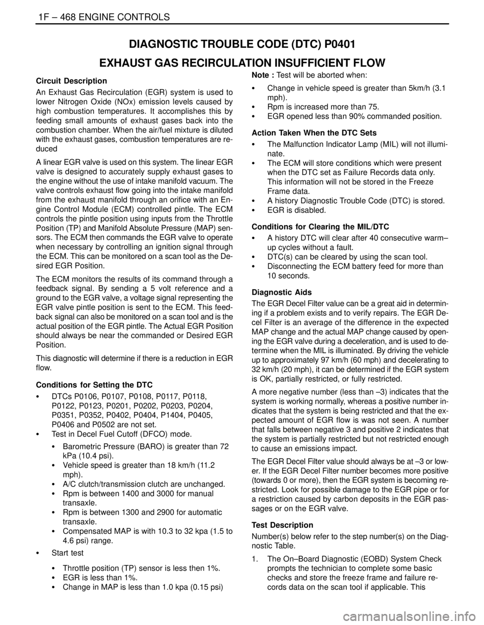
DIAGNOSTIC TROUBLE CODE (DTC) P0401
EXHAUST GAS RECIRCULATION INSUFFICIENT FLOW
Circuit Description
An Exhaust Gas Recirculation (EGR) system is used to
lower Nitrogen Oxide (NOx) emission levels caused by
high combustion temperatures. It accomplishes this by
feeding small amounts of exhaust gases back into the
combustion chamber. When the air/fuel mixture is diluted
with the exhaust gases, combustion temperatures are re-
duced
A linear EGR valve is used on this system. The linear EGR
valve is designed to accurately supply exhaust gases to
the engine without the use of intake manifold vacuum. The
valve controls exhaust flow going into the intake manifold
from the exhaust manifold through an orifice with an En-
gine Control Module (ECM) controlled pintle. The ECM
controls the pintle position using inputs from the Throttle
Position (TP) and Manifold Absolute Pressure (MAP) sen-
sors. The ECM then commands the EGR valve to operate
when necessary by controlling an ignition signal through
the ECM. This can be monitored on a scan tool as the De-
sired EGR Position.
The ECM monitors the results of its command through a
feedback signal. By sending a 5 volt reference and a
ground to the EGR valve, a voltage signal representing the
EGR valve pintle position is sent to the ECM. This feed-
back signal can also be monitored on a scan tool and is the
actual position of the EGR pintle. The Actual EGR Position
should always be near the commanded or Desired EGR
Position.
This diagnostic will determine if there is a reduction in EGR
flow.
Conditions for Setting the DTC
S DTCs P0106, P0107, P0108, P0117, P0118,
P0122, P0123, P0201, P0202, P0203, P0204,
P0351, P0352, P0402, P0404, P1404, P0405,
P0406 and P0502 are not set.
S Test in Decel Fuel Cutoff (DFCO) mode.
S Barometric Pressure (BARO) is greater than 72
kPa (10.4 psi).
S Vehicle speed is greater than 18 km/h (11.2
mph).
S A/C clutch/transmission clutch are unchanged.
S Rpm is between 1400 and 3000 for manual
transaxle.
S Rpm is between 1300 and 2900 for automatic
transaxle.
S Compensated MAP is with 10.3 to 32 kpa (1.5 to
4.6 psi) range.
S Start test
S Throttle position (TP) sensor is less then 1%.
S EGR is less than 1%.
S Change in MAP is less than 1.0 kpa (0.15 psi)Note : Test will be aborted when:
S Change in vehicle speed is greater than 5km/h (3.1
mph).
S Rpm is increased more than 75.
S EGR opened less than 90% commanded position.
Action Taken When the DTC Sets
S The Malfunction Indicator Lamp (MIL) will not illumi-
nate.
S The ECM will store conditions which were present
when the DTC set as Failure Records data only.
This information will not be stored in the Freeze
Frame data.
S A history Diagnostic Trouble Code (DTC) is stored.
S EGR is disabled.
Conditions for Clearing the MIL/DTC
S A history DTC will clear after 40 consecutive warm–
up cycles without a fault.
S DTC(s) can be cleared by using the scan tool.
S Disconnecting the ECM battery feed for more than
10 seconds.
Diagnostic Aids
The EGR Decel Filter value can be a great aid in determin-
ing if a problem exists and to verify repairs. The EGR De-
cel Filter is an average of the difference in the expected
MAP change and the actual MAP change caused by open-
ing the EGR valve during a deceleration, and is used to de-
termine when the MIL is illuminated. By driving the vehicle
up to approximately 97 km/h (60 mph) and decelerating to
32 km/h (20 mph), it can be determined if the EGR system
is OK, partially restricted, or fully restricted.
A more negative number (less than –3) indicates that the
system is working normally, whereas a positive number in-
dicates that the system is being restricted and that the ex-
pected amount of EGR flow is was not seen. A number
that falls between negative 3 and positive 2 indicates that
the system is partially restricted but not restricted enough
to cause an emissions impact.
The EGR Decel Filter value should always be at –3 or low-
er. If the EGR Decel Filter number becomes more positive
(towards 0 or more), then the EGR system is becoming re-
stricted. Look for possible damage to the EGR pipe or for
a restriction caused by carbon deposits in the EGR pas-
sages or on the EGR valve.
Test Description
Number(s) below refer to the step number(s) on the Diag-
nostic Table.
1. The On–Board Diagnostic (EOBD) System Check
prompts the technician to complete some basic
checks and store the freeze frame and failure re-
cords data on the scan tool if applicable. This
Page 716 of 2643

1F – 470IENGINE CONTROLS
DAEWOO V–121 BL4
DIAGNOSTIC TROUBLE CODE (DTC) P0402
EXHAUST GAS RECIRCULATION EXCESSIVE FLOW
Circuit Description
An Exhaust Gas Recirculation (EGR) system is used to
lower Nitrogen Oxide (NOx) emission levels caused by
high combustion temperatures. It accomplishes this by
feeding small amounts of exhaust gases back into the
combustion chamber. When the air/fuel mixture is diluted
with the exhaust gases, combustion temperatures are re-
duced
A linear EGR valve is used on this system. The linear EGR
valve is designed to accurately supply exhaust gases to
the engine without the use of intake manifold vacuum. The
valve controls exhaust flow going into the intake manifold
from the exhaust manifold through an orifice with an En-
gine Control Module (ECM) controlled pintle. The ECM
controls the pintle position using inputs from the Throttle
Position (TP) and Manifold Absolute Pressure (MAP) sen-
sors. The ECM then commands the EGR valve to operate
when necessary by controlling an ignition signal through
the ECM. This can be monitored on a scan tool as the De-
sired EGR Position.
The ECM monitors the results of its command through a
feedback signal. By sending a 5 volt reference and a
ground to the EGR valve, a voltage signal representing the
EGR valve pintle position is sent to the ECM. This feed-
back signal can also be monitored on a scan tool and is the
actual position of the EGR pintle. The Actual EGR Position
should always be near the commanded or Desired EGR
Position.
This Diagnostic Trouble Code (DTC) will detect an EGR
open to a large valve during crank. Crank time may be ex-
cessive with an open EGR valve.Conditions for Setting the DTC
S EGR position is greater than 70% for more than 3
seconds during cranking.
S Engine cranking (not running).
S Ignition voltage is between 10 and 16 volts.
Action Taken When the DTC Sets
S The Malfunction Indicator Lamp (MIL) will illuminate
after three consecutive with a fail.
S The ECM will record operating conditions at the
time the diagnostic fails. This information will be
stored in the Freeze Frame and Failure Records
buffers.
S A history Diagnostic Trouble Code (DTC) is stored.
S EGR is disabled.
Conditions for Clearing the MIL/DTC
S The MIL will turns off after four consecutive ignition
cycles in which the diagnostic runs without a fault.
S A history DTC will clear after 40 consecutive warm–
up cycles without a fault.
S DTC(s) can be cleared by using the scan tool.
S Disconnecting the ECM battery feed for more than
10 seconds.
Diagnostic Aids
Due to moisture associated with exhaust systems, the
EGR valve may freeze and stick in cold weather at times.
After the vehicle is brought into a warm shop for repairs,
the valve warms and the problem disappears. By watching
the Actual EGR and Desired EGR Positions on a cold ve-
hicle with a scan tool, the fault can be easily verified.
Check the freeze frame data to determine if the DTC set
when the vehicle was cold by viewing the Engine Coolant
Temperature (ECT).
Page 720 of 2643

1F – 474IENGINE CONTROLS
DAEWOO V–121 BL4
DIAGNOSTIC TROUBLE CODE (DTC) P0404
EXHAUST GAS RECIRCULATION OPEN VALVE POSITION
ERROR
Circuit Description
An Exhaust Gas Recirculation (EGR) system is used to
lower Nitrogen Oxide (NOx) emission levels caused by
high combustion temperatures. It accomplishes this by
feeding small amounts of exhaust gases back into the
combustion chamber. When the air/fuel mixture is diluted
with the exhaust gases, combustion temperatures are re-
duced
A linear EGR valve is used on this system. The linear EGR
valve is designed to accurately supply exhaust gases to
the engine without the use of intake manifold vacuum. The
valve controls exhaust flow going into the intake manifold
from the exhaust manifold through an orifice with an En-
gine Control Module (ECM) controlled pintle. The ECM
controls the pintle position using inputs from the Throttle
Position (TP) and Manifold Absolute Pressure (MAP) sen-
sors. The ECM then commands the EGR valve to operate
when necessary by controlling an ignition signal through
the ECM. This can be monitored on a scan tool as the De-
sired EGR Position.
The ECM monitors the results of its command through a
feedback signal. By sending a 5 volt reference and a
ground to the EGR valve, a voltage signal representing the
EGR valve pintle position is sent to the ECM. This feed-
back signal can also be monitored on a scan tool and is the
actual position of the EGR pintle. The Actual EGR Position
should always be near the commanded or Desired EGR
Position.
This Diagnostic Trouble Code (DTC) will detect an open
valve position.
Conditions for Setting the DTCS Difference between current and commended posi-
tion is greater than 15%.
S Desired EGR position is greater than 0.
S Change in Desired EGR is less than 3%.
S Engine is running.
S Ignition voltage is between 11.7 and 16 volts.
S Air temperature is greater than 3°C.
S DTCs P0112, P0113 P0405, P0406, and P0502 are
not set.
Action Taken When the DTC Sets
S The Malfunction Indicator Lamp (MIL) will illumi-
nate, after three concecutive ignition cycle with a
fail.
S The ECM will record operating conditions at the
time the diagnostic fails. This information will be
stored in the Freeze Frame and Failure Records
buffers.
S A history Diagnostic Trouble Code (DTC) is stored.
S EGR is disabled.
Conditions for Clearing the MIL/DTC
S The MIL will turns off after four consecutive ignition
cycles in which the diagnostic runs without a fault.
S A history DTC will clear after 40 consecutive warm–
up cycles without a fault.
S DTC(s) can be cleared by using the scan tool.
S Disconnecting the ECM battery feed for more than
10 seconds.
Diagnostic Aids
Due to moisture associated with exhaust systems, the
EGR valve may freeze and stick in cold weather at times.
After the vehicle is brought into a warm shop for repairs,
the valve warms and the problem disappears. By watching
Page 724 of 2643

1F – 478IENGINE CONTROLS
DAEWOO V–121 BL4
DIAGNOSTIC TROUBLE CODE (DTC) P0405
EXHAUST GAS RECIRCULATION PINTLE POSITION LOW
VOLTAGE
Circuit Description
An Exhaust Gas Recirculation (EGR) system is used to
lower Nitrogen Oxide (NOx) emission levels caused by
high combustion temperatures. It accomplishes this by
feeding small amounts of exhaust gases back into the
combustion chamber. When the air/fuel mixture is diluted
with the exhaust gases, combustion temperatures are re-
duced
A linear EGR valve is used on this system. The linear EGR
valve is designed to accurately supply exhaust gases to
the engine without the use of intake manifold vacuum. The
valve controls exhaust flow going into the intake manifold
from the exhaust manifold through an orifice with an En-
gine Control Module (ECM) controlled pintle. The ECM
controls the pintle position using inputs from the Throttle
Position (TP) and Manifold Absolute Pressure (MAP) sen-
sors. The ECM then commands the EGR valve to operate
when necessary by controlling an ignition signal through
the ECM. This can be monitored on a scan tool as the De-
sired EGR Position.
The ECM monitors the results of its command through a
feedback signal. By sending a 5 volt reference and a
ground to the EGR valve, a voltage signal representing the
EGR valve pintle position is sent to the ECM. This feed-
back signal can also be monitored on a scan tool and is the
actual position of the EGR pintle. The Actual EGR Position
should always be near the commanded or Desired EGR
Position. This diagnostic Trouble Code (DTC) will detect
an open or short circuit.Conditions for Setting the DTC
S EGR position signal is less than 2%.
S Ignition voltage is between 11.7 and 16 volts.
S Fail condition last more than 10 seconds.
Action Taken When the DTC Sets
S The Malfunction Indicator Lamp (MIL) will illuminate
after three consecutive ignition cycle with a fail.
S The ECM will record operating conditions at the
time the diagnostic fails. This information will be
stored in the Freeze Frame and Failure Records
buffers.
S A history Diagnostic Trouble Code (DTC) is stored.
S EGR is disabled.
Conditions for Clearing the MIL/DTC
S The MIL will turns off after four consecutive ignition
cycles in which the diagnostic runs without a fault.
S A history DTC will clear after 40 consecutive warm–
up cycles without a fault.
S DTC(s) can be cleared by using the scan tool.
S Disconnecting the ECM battery feed for more than
10 seconds.
Diagnostic Aids
Due to moisture associated with exhaust systems, the
EGR valve may freeze and stick in cold weather at times.
After the vehicle is brought into a warm shop for repairs,
the valve warms and the problem disappears. By watching
the Actual EGR and Desired EGR Positions on a cold ve-
hicle with a scan tool, the fault can be easily verified.
Check the freeze frame data to determine if the DTC set
when the vehicle was cold by viewing the Engine Coolant
Temperature (ECT).