tire pressure DAEWOO NUBIRA 2004 Service Owner's Manual
[x] Cancel search | Manufacturer: DAEWOO, Model Year: 2004, Model line: NUBIRA, Model: DAEWOO NUBIRA 2004Pages: 2643, PDF Size: 80.54 MB
Page 923 of 2643

2C – 6IFRONT SUSPENSION
DAEWOO V–121 BL4
BALL JOINT AND KNUCKLE
Ball Joint Inspection
1. Raise the front of the vehicle to allow the front sus-
pension to hang free.
2. Grasp the tire at the top and the bottom.
3. Move the top of the tire in an in–and–out motion.
4. Look for any horizontal movement of the knuckle
relative to the control arm.
5. Ball joints must be replaced under the following
conditions:
S The joint is loose.
S The ball seal is cut.
S The ball stud is disconnected from the knuckle.
S The ball stud is loose at the knuckle.
S The ball stud can be twisted in its socket with
finger pressure.
Ball Stud Inspection
Make sure to check the tightness of the ball stud in the
knuckle boss during each inspection of the ball joint. One
way to inspect the ball stud for wear is to shake the wheel
and feel for movement of the stud end at the knuckle boss.Another way to inspect the ball stud for wear is to check
the fastener torque at the pinch nut. A loose nut can indi-
cate a stressed stud or a hole in the knuckle boss.
Worn or damaged ball joints and knuckles must be re-
placed.
EXCESSIVE FRICTION CHECK
Use the following procedure to check for excessive friction
in the front suspension:
1. Enlist the help of another technician to lift up on the
front bumper, raising the vehicle as high as pos-
sible.
2. Slowly release the bumper, allowing the vehicle to
assume its normal trim height. See ”General Speci-
fications” in this section.
3. Measure the distance from the street level to the
center of the bumper.
4. Push down on the bumper, release slowly, and al-
low the vehicle to assume its normal trim height.
5. Measure the distance from the street level to the
center of the bumper.
6. The difference between the two measurements
should be less than 12.7 mm (0.5 inch). If the differ-
ence exceeds this limit, inspect the control arms,
the struts, and the ball joints for damage or wear.
Page 945 of 2643

REAR SUSPENSION 2D – 3
DAEWOO V–121 BL4
DIAGNOSIS
EXCESSIVE FRICTION CHECK
Check excessive friction in the rear suspension as follows:
1. With the aid of a helper, lift up on the rear bumper
and raise the vehicle as high as possible. Slowly
release the bumper and allow the car to assume
normal trim height.
2. Measure the distance from the floor to the center of
the bumper.
3. Push down on the bumper, release slowly, and al-
low the car to assume normal trim height.4. Measure the distance from the floor to the center of
the bumper.
The difference between the two measurements should be
less than 12.7 mm (0.50 inch). If the difference exceeds
this limit, inspect the control arms for damage or wear.
STRUT DAMPENER
A strut dampener is basically a shock absorber. However,
strut dampeners are easier to extend and retract by hand
than are shock absorbers.
Struts Seem Weak
ChecksAction
Check the tire pressures.Adjust the tire pressures to the specifications on the tire
placard.
Check the load conditions under which the vehicle is nor-
mally driven.Consult with the owner to confirm the owner’s understand-
ing of normal load conditions.
Check the compression and rebound effectiveness of the
strut dampener.Quickly push down and then lift up on the corner of the
bumper nearest the strut dampener being tested.
Compare the compression and rebound with those of a
similar vehicle that has an acceptable ride quality.
Replace the strut dampener, if needed.
Struts Are Noisy
ChecksAction
Check the mountings for looseness or damage.Tighten the strut dampener. Replace the strut dampener,
if needed.
Check the compression and rebound effectiveness of the
strut dampener.Quickly push down and then lift up on the corner of the
bumper nearest the strut dampener being tested.
Compare the compression and rebound with those of a
similar vehicle that has an acceptable ride quality.
Replace the strut dampener, if needed.
Leaks
ChecksAction
Check for a slight trace of fluid.The strut dampener is OK.
Check the seal cover on the fully extended strut.Replace the strut dampener.
Check for an excessive amount of fluid on the strut damp-
ener.Replace the strut dampener.
Page 963 of 2643

SECTION : 2E
TIRES AND WHEELS
TABLE OF CONTENTS
SPECIFICATIONS2E–1 . . . . . . . . . . . . . . . . . . . . . . . . . .
Tire Size and Pressure Specifications 2E–1. . . . . . . .
Inflation Pressure Conversion Specifications 2E–2. .
Fastener Tightening Specifications 2E–2. . . . . . . . . . .
DIAGNOSIS2E–2 . . . . . . . . . . . . . . . . . . . . . . . . . . . . . . . .
Wheel Runout 2E–2. . . . . . . . . . . . . . . . . . . . . . . . . . . . .
MAINTENANCE AND REPAIR2E–3 . . . . . . . . . . . . . . .
ON–VEHICLE SERVICE 2E–3. . . . . . . . . . . . . . . . . . . . .
Wheel 2E–3. . . . . . . . . . . . . . . . . . . . . . . . . . . . . . . . . . . .
On–Vehicle Balancing 2E–4. . . . . . . . . . . . . . . . . . . . . .
UNIT REPAIR 2E–5. . . . . . . . . . . . . . . . . . . . . . . . . . . . . .
Alloy Wheel Porosity 2E–5. . . . . . . . . . . . . . . . . . . . . . .
Alloy Wheel Refinishing 2E–5. . . . . . . . . . . . . . . . . . . . .
Off–Vehicle Balancing 2E–7. . . . . . . . . . . . . . . . . . . . . . Correcting Non–Uniform Tires 2E–7. . . . . . . . . . . . . . .
Tire and Wheel Match–Mounting 2E–8. . . . . . . . . . . . .
Tire Mounting and Dismounting 2E–8. . . . . . . . . . . . . .
GENERAL DESCRIPTION AND SYSTEM
OPERATION 2E–9 . . . . . . . . . . . . . . . . . . . . . . . . . . . . .
Tire and Wheel Balancing 2E–9. . . . . . . . . . . . . . . . . . .
Tire Chain Usage 2E–9. . . . . . . . . . . . . . . . . . . . . . . . . .
Replacement Tires 2E–10. . . . . . . . . . . . . . . . . . . . . . . .
All Season Tires 2E–10. . . . . . . . . . . . . . . . . . . . . . . . . .
Passenger Metric Sized Tires 2E–10. . . . . . . . . . . . . .
Tire Label 2E–10. . . . . . . . . . . . . . . . . . . . . . . . . . . . . . . .
Spare Tire 2E–10. . . . . . . . . . . . . . . . . . . . . . . . . . . . . . .
Wheels 2E–10. . . . . . . . . . . . . . . . . . . . . . . . . . . . . . . . . .
Inflation o Tires 2E–11. . . . . . . . . . . . . . . . . . . . . . . . . . .
SPECIFICATIONS
TIRE SIZE AND PRESSURE SPECIFICATIONS
Inflation Pressure at Full Load
TiresWheelFrontRear
kPapsikPapsi
175 / 70R145.5J x 14(Steel)2053020530
175 / 70R145.5J x 14(Alloy)2053020530
T125 / 70D154T x 154156041560
185 / 65R145.5J x 14(Steel)2053020530
185 / 65R145.5J x 14(Alloy)2053020530
T125 / 70D154T x 154156041560
195 / 55R156J x 15(Steel)2053020530
195 / 55R156J x 15(Alloy)2053020530
195 / 55R156J x 15
(Alloy, Sporty)2053020530
T125 / 70D154T x 154156041560
Page 964 of 2643
2E – 2ITIRES AND WHEELS
DAEWOO V–121 BL4
INFLATION PRESSURE CONVERSION SPECIFICATIONS
kPaPsikPaPsikPaPsi
140201852723534
145211902824035
155222002925036
160232053027540
165242153131045
170252203234550
FASTENER TIGHTENING SPECIFICATIONS
ApplicationNSmLb–FtLb–In
Wheel Bolt (Alloy Wheel)10074–
Wheel Bolt (Steel Wheel)10074–
DIAGNOSIS
WHEEL RUNOUT
Measure wheel runout with an accurate dial indicator.
Measurements may be taken with the wheels either on or
off the vehicle, using an accurate mounting surface such
as a wheel balancer. Measurements may be taken with or
without the tire mounted on the wheel.
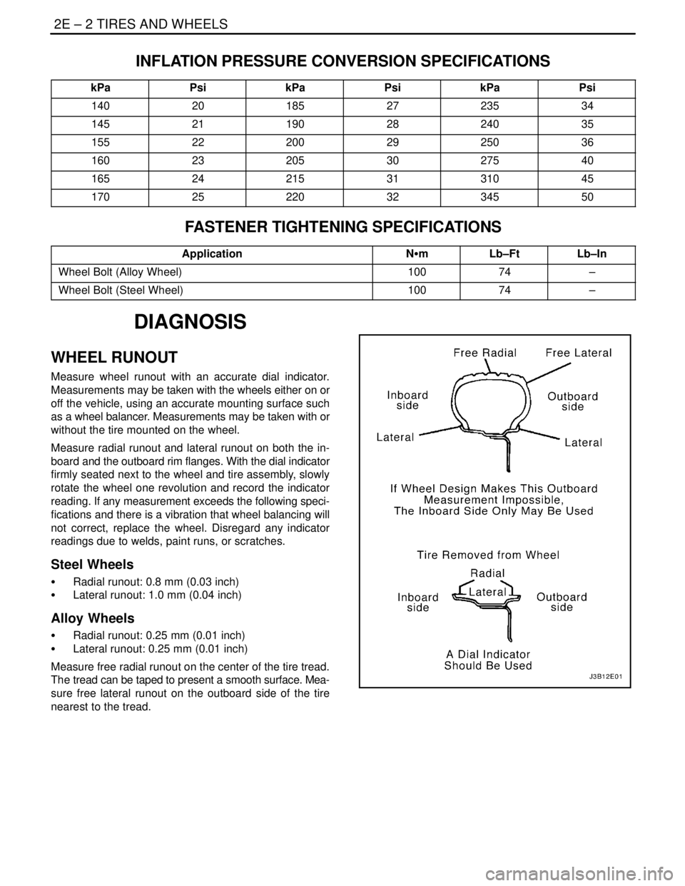
Measure radial runout and lateral runout on both the in-
board and the outboard rim flanges. With the dial indicator
firmly seated next to the wheel and tire assembly, slowly
rotate the wheel one revolution and record the indicator
reading. If any measurement exceeds the following speci-
fications and there is a vibration that wheel balancing will
not correct, replace the wheel. Disregard any indicator
readings due to welds, paint runs, or scratches.
Steel Wheels
S Radial runout: 0.8 mm (0.03 inch)
S Lateral runout: 1.0 mm (0.04 inch)
Alloy Wheels
S Radial runout: 0.25 mm (0.01 inch)
S Lateral runout: 0.25 mm (0.01 inch)
Measure free radial runout on the center of the tire tread.
The tread can be taped to present a smooth surface. Mea-
sure free lateral runout on the outboard side of the tire
nearest to the tread.
Page 967 of 2643

TIRES AND WHEELS 2E – 5
DAEWOO V–121 BL4
UNIT REPAIR
ALLOY WHEEL POROSITY
Wheel repairs that use welding, heating or peening are not
approved.
1. Raise and suitably support the vehicle.
2. Remove the wheel. Refer to ”Wheel” in this sec-
tion.
CAUTION : To avoid serious injury, do not stand over
the tire when inflating, because the bead may break
when it snaps over the safety hump. Do not exceed
275 kPa (40 psi) of air pressure in any tire if the beads
are not seated. If 275 kPa (40 psi) of air pressure will
not seat the beads, deflate the tire. Relubricate the
beads. Reinflate the tire. Overinflation may cause the
bead to break and cause serious injury.
3. Locate leaking areas by inflating the tire to 345 kPa
(50 psi) and dipping the tire and wheel assembly
into a water bath.
4. Mark the leak areas and remove the tire from the
wheel.
5. Scuff the inside wheel surface at the leak area with
80–grit sandpaper. Clean the leak area with a gen-
eral–purpose cleaner.
6. Apply a 3.3 mm (0.13 inch) thick layer of adhesive/
sealant to the leak area. Allow it to dry for 12 hours.
7. Install the tire on the wheel. Inflate the tire to 345
kPa (50 psi) and check for leaks as in step 3.
8. Adjust the tire pressure to meet specifications. Re-
fer to ”Tire Size and Pressure Specifications” in
this section.
9. Balance the wheel. Refer to ”Tire and Wheel Bal-
ancing” in this section.
10. Install the wheel. Refer to ”Wheel” in this section.
11. Lower the vehicle.
ALLOY WHEEL REFINISHING
A protective clear or color coating is applied to the surface
of the original equipment cast alloy wheels. Surface deg-
radation can develop if this clear coating is damaged or re-
moved. This can happen at some automatic car wash fa-
cilities that use silicon carbide–tipped tire brushes to clean
white walls and tires. Once the protective coating is dam-
aged, exposure to caustic cleaners or road salt causes fur-
ther surface degradation. The following procedure details
how to strip, clean and recoat alloy wheels.
CAUTION : To avoid serious personal injury, follow
the manufacturer’s recommendations and cautions
when using these materials.
Required materials:
S Amchem Alumi Prep No. 33. Stock No. DX533 or
equivalent cleaning and conditioning chemical for
alloys.
Page 970 of 2643

2E – 8ITIRES AND WHEELS
DAEWOO V–121 BL4
TIRE AND WHEEL
MATCH–MOUNTING
The tires and wheels are match–mounted at the assembly
plant. Match–mounting aligns the radially stiffest part of
the tire, or high spot, to the smallest radius, or low spot, of
the wheel.
The high spot of the tire is originally marked by a red paint
mark or an adhesive label on the outboard sidewall.
The low spot of the wheel will be at the location of the valve
stem.
Before dismounting a tire from its wheel, scribe a line on
the tire at the valve stem to assure that it is remounted in
the same position.
Replacement tires that are of original equipment quality
will have their high and low spot marked in the same man-
ner.
TIRE MOUNTING AND DISMOUNTING
Notice : Use a tire–changing machine to mount or dis-
mount the tires. Follow the equipment manufacturer’s in-
structions. Do not use hand tools or tire irons to change
tires. These tools may damage the beads or the wheel rim.
1. Clean the rim bead seats with a wire brush or
coarse steel wool to remove lubricants, old rubber,
and light rust. Before mounting or dismounting a
tire, lubricate the bead area well with an approved
tire lubricant.
CAUTION : To avoid serious injury, do not stand over
the tire when inflating it, because the bead may break
when it snaps over the safety hump. Do not exceed
275 kPa (40 psi) of air pressure in any tire if the beads
are not seated. If 275 kPa (40 psi) of air pressure will
not seat the beads, deflate the tire. Relubricate the
bead and reinflate the tire. Overinflation may cause
the bead to break and cause serious injury.
2. fter mounting the tire, inflate it until the beads are
seated. Never exceed 275 kPa (40 psi) to seat the
beads.
3. Install the valve core and inflate the tire to the prop-
er pressure. Make sure the locating ring outside of
the bead of the tire shows around the rim flanges of
the wheel on both sides. This positioning of the tire
will insure that the bead of the tire is seated.
Page 971 of 2643
TIRES AND WHEELS 2E – 9
DAEWOO V–121 BL4
GENERAL DESCRIPTION
AND SYSTEM OPERATION
TIRE AND WHEEL BALANCING
There are two types of tire and wheel balancing: static and
dynamic.
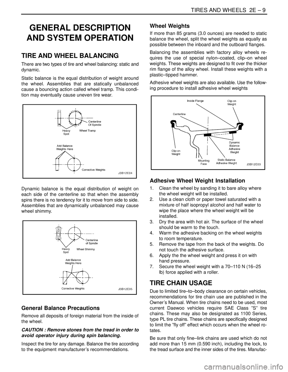
Static balance is the equal distribution of weight around
the wheel. Assemblies that are statically unbalanced
cause a bouncing action called wheel tramp. This condi-
tion may eventually cause uneven tire wear.
Dynamic balance is the equal distribution of weight on
each side of the centerline so that when the assembly
spins there is no tendency for it to move from side to side.
Assemblies that are dynamically unbalanced may cause
wheel shimmy.
General Balance Precautions
Remove all deposits of foreign material from the inside of
the wheel.
CAUTION : Remove stones from the tread in order to
avoid operator injury during spin balancing.
Inspect the tire for any damage. Balance the tire according
to the equipment manufacturer’s recommendations.
Wheel Weights
If more than 85 grams (3.0 ounces) are needed to static
balance the wheel, split the wheel weights as equally as
possible between the inboard and the outboard flanges.
Balancing the assemblies with factory alloy wheels re-
quires the use of special nylon–coated, clip–on wheel
weights. These weights are designed to fit over the thicker
rim flange of the alloy wheel. Install these weights with a
plastic–tipped hammer.
Adhesive wheel weights are also available. Use the follow-
ing procedure to install adhesive wheel weights
Adhesive Wheel Weight Installation
1. Clean the wheel by sanding it to bare alloy where
the wheel weight will be installed.
2. Use a clean cloth or paper towel saturated with a
mixture of half isopropyl alcohol and half water to
wipe the place where the wheel weight will be
installed.
3. Dry the area with hot air. The surface of the wheel
should be warm to the touch.
4. Warm the adhesive backing on the wheel weights
to room temperature.
5. Remove the tape from the back of the weights. Do
not touch the adhesive surface.
6. Apply the the wheel weight and press it on with
hand pressure.
7. Secure the wheel weight with a 70–110 N (16–25
lb) force applied with a roller.
TIRE CHAIN USAGE
Due to limited tire–to–body clearance on certain vehicles,
recommendations for tire chain use are published in the
Owner ’s Manual. When tire chains need to be used, most
current Daewoo vehicles require SAE Class ”S” tire
chains. These may also be designated as 1100 Series,
type PL tire chains. These chains are specifically designed
to limit the ”fly off” effect which occurs when the wheel ro-
tates.
Be sure that only fine–link chains are used which do not
add more than 15 mm (0.590 inch), including the lock, to
the tread surface and the inner sides of the tires. Manufac-
Page 972 of 2643

2E – 10ITIRES AND WHEELS
DAEWOO V–121 BL4
turers of tire chains have a specific chain size for each tire
size to ensure a proper fit when the chain is installed. Be
sure to purchase the correct chains for the tires on which
they are to be used. Use rubber adjusters to take up any
slack or clearance in loose chains.
Use of chains may adversely affect vehicle handling.
When tire chains are installed, follow these precautions:
S Adjust speed to road conditions.
S Avoid sharp turns.
S Avoid locked–wheel braking.
To prevent chain damage to the vehicle, install the chains
on the front tires as tightly as possible. Tighten them again
after driving 0.4 to 0.8 kilometer (0.3 to 0.5 mile). The use
of chains on the rear tires is not recommended because
they may contact the vehicle and possibly damage it. If
chains must be used on the rear tires, be sure there is suffi-
cient clearance between the chains and the body. Do not
exceed 70 km/h (45 mph) or the chain manufacturer’s
speed limit, if lower. Avoid large bumps, potholes, severe
turns and any other maneuvers which could cause the
tires to bounce. Follow any other instructions of the chain
manufacturer which do not disagree with the above in-
structions.
REPLACEMENT TIRES
A tire performance criteria (TPC) specification number is
molded in the sidewall near the tire size of all original
equipment tires. This specification number assures that
the tire meets performance standards for traction, endur-
ance, dimensions, noise, handling and rolling resis–tance.
Usually a specific TPC number is assigned to each tire
size.
CAUTION : Do not mix different types of tires on the
same vehicle such as radial, bias and bias–belted
tires except in emergencies, because vehicle han-
dling may be seriously affected and may result in loss
of control.
Use only replacement tires with the same size, load range,
and construction as the original. The use of any other tire
size or construction type may seriously affect ride, han-
dling, speedometer/odometer calibration, vehicle ground
clearance, and tire clearance to the body and the chassis.
This does not apply to the spare tire furnished with the ve-
hicle.
It is recommended that new tires be installed in pairs on
the same axle.
If it is necessary to replace only one tire, pair it with the tire
having the most tread to equalize the braking action.
Although they may appear different in tread design, tires
built by different manufacturers with identical TPC specifi-
cations may be used on the same vehicle.
ALL SEASON TIRES
Most vehicles are now equipped with steel–belted all sea-
son radial tires as standard equipment. These tires qualify
as snow tires, with a 37 percent higher average rating for
snow traction than the non–all season radial tires pre-
viously used. Other performance areas, such as wet trac-
tion, rolling resistance, tread life, and air retention, have
also been improved. This was done by improvements in
both tread design and tread compounds. These tires are
identified by an ”M + S” molded in the tire sidewall following
the size number. The suffix ”MS” is also molded in the side-
wall after the TPC specification number.
The optional handling tires used on some vehicles are not
all season tires. These will not have the ”MS” marking after
the tire size or the TPC specification number.
PASSENGER METRIC SIZED TIRES
All Daewoo vehicles now use Passenger (P) metric sized
tires. P–metric tires are available in two load ranges: stan-
dard load (35 psi maximum) and extra load (41 psi maxi-
mum). Most passenger vehicle tires are standard load.
Most P–metric tire sizes do not have exact corresponding
alphanumeric tire sizes. For example, a P175/70R13 is
not exactly equal in size and load–carrying capacity to an
FR70–13. For this reason, replacement tires should be of
the same TPC specification number as the originals. If P–
metric tires must be replaced with other sizes, consult a
tire dealer. Tire companies can best recommend the clos-
est match of alphanumeric to P–metric sizes within their
own tire lines.
The metric term for measuring tire inflation pressure is the
kilopascal (kPa). Tire pressure may be printed in both kPa
and psi. One psi equals 6.895 kPa.
See the tire label or refer to ”Tire Size and Pressure Speci-
fications” in this section for tire inflation pressures.
TIRE LABEL
The tire label is permanently located on the rear face of the
driver’s door and should be referred to for tire information.
It lists the maximum vehicle load, the tire size (including
the spare tire), and the cold inflation pressure (including
the spare tire).
SPARE TIRE
The notchback and the wagon come equipped with a full–
sized tire on a steel wheel. The hatchback comes
equipped with a reduced–sized temporary tire on a steel
wheel.
WHEELS
Wheels must be replaced if they are bent, dented, have
excessive lateral or radial runout, leak air through welds,
have elongated bolt holes, or if the wheel bolts won’t stay
tight or are heavily rusted. Wheels with excessive runout
may cause vehicle vibration. Replacement wheels must
be equivalent to the original equipment wheels in load ca-
Page 973 of 2643

TIRES AND WHEELS 2E – 11
DAEWOO V–121 BL4
pacity, diameter, rim width, offset, and mounting configu-
ration. A wheel of improper size or type may affect wheel
and bearing life, brake cooling, speedometer/odometer
calibration, vehicle ground clearance, and tire clearance
to the body and the chassis. The wheel offset is 49 ± 1 mm
(1.93 ± 0.04 inches). Steel wheels may be identified by a
two– or three–letter code stamped into the rim near the
valve stem. Alloy wheels should have the code, the part
number, and the manufacturer ID cast into the back side.
INFLATION O TIRES
The pressure recommended for any vehicle line is careful-
ly calculated to give a satisfactory ride, handling, tread life,
and load–carrying capacity.
Tire pressure should be checked monthly or before any
extended trip. Check the tires when they are cold, after the
vehicle has sat for 3 hours or more, or has been driven less
than 1 mile. Set the tire pressure to the specifications on
the tire label located on the rear face of the driver’s door.
Tire inflation pressure is also given under ”Tire Size and
Pressure Specifications” in this section.
Valve caps or extensions should be on the valves to keep
dust and water out.
For sustained driving at speeds up to 140 km/h (85 mph),
inflate the tires to the pressure recommended on the tire.
Sustained driving at speeds faster than 140 km/h (85mph), even if permitted by law, is not advised unless the
vehicle has special high–speed tires available from many
tire dealers. Tire pressures may increase as much as 41
kPa (6 psi) when the tires are hot.
Higher than recommended tire pressure can cause
S Hard ride.
S Tire bruising or damage.
S Rapid tread wear at the center of the tire.
Lower than recommended pressure can cause
S Tire squeal on turns.
S Hard steering.
S Rapid and uneven wear on the edges of the tread.
S Tire rim bruises and rupture.
S Tire cord breakage.
S High tire temperatures.
Unequal tire pressures on same axle can cause
S Uneven braking.
S Steering lead.
S Reduced handling.
S Swerve on acceleration.
S Torque steer.
Page 1021 of 2643

HYDRAULIC BRAKES 4A – 5
DAEWOO V–121 BL4
DIAGNOSIS
BRAKE SYSTEM TESTING
Brakes should be tested on a dry, clean, reasonably
smooth and level roadway. A true test of brake perfor-
mance cannot be made if the roadway is wet, greasy, or
covered with loose dirt whereby all tires do not grip the
road equally. Testing will also be adversely affected if the
roadway is crowned so as to throw the weight so roughly
that the wheels tend to bounce.
Test the brakes at different vehicle speeds with both light
and heavy pedal pressure; however, avoid locking the
brakes and sliding the tires. Locked brakes and sliding
tires do not indicate brake efficiency since heavily braked,
but turning, wheels will stop the vehicle in less distance
than locked brakes. More tire–to–road friction is present
with a heavily–braked, turning tire than with a sliding tire.
Because of the high deceleration capability, a firmer pedal
may be felt at higher deceleration levels.
There are three major external conditions that affect brake
performance:
S Tires having unequal contact and grip of the road
will cause unequal braking. Tires must be equally
inflated, and the tread pattern of the right and the
left tires must be approximately equal.
S Unequal loading of the vehicle can affect the brake
performance since the most heavily loaded wheels
require more braking power, and thus more braking
effort, than the others.
S Misalignment of the wheels, particularly conditions
of excessive camber and caster, will cause the
brakes to pull to one side.
To check for brake fluid leaks, hold constant foot pressure
on the pedal with the engine running at idle and the shift
lever in NEUTRAL. If the pedal gradually falls away with
the constant pressure, the hydraulic system may be leak-
ing. Perform a visual check to confirm any suspected
leaks.
Check the master cylinder fluid level. While a slight drop
in the reservoir level results from normal lining wear, an ab-
normally low level indicates a leak in the system. The hy-
draulic system may be leaking either internally or external-
ly. Refer to the procedure below to check the master
cylinder. Also, the system may appear to pass this test
while still having a slight leak. If the fluid level is normal,
check the vacuum booster pushrod length. If an incorrect
pushrod length is found, adjust or replace the rod.
Check the master cylinder using the following procedure:
S Check for a cracked master cylinder casting or
brake fluid leaking around the master cylinder.
Leaks are indicated only if there is at least one drop
of fluid. A damp condition is not abnormal.S Check for a binding pedal linkage and for an incor-
rect pushrod length. If both of these parts are in
satisfactory condition, disassemble the master cyl-
inder and check for an elongated or swollen primary
cylinder or piston seals. If swollen seals are found,
substandard or contaminated brake fluid should be
suspected. If contaminated brake fluid is found, all
the components should be disassembled and
cleaned, and all the rubber components should be
replaced. All of the pipes must also be flushed.
Improper brake fluid, or mineral oil or water in the fluid,
may cause the brake fluid to boil or cause deterioration of
the rubber components. If the primary piston cups in the
master cylinder are swollen, then the rubber parts have
deteriorated. This deterioration may also be evidenced by
swollen wheel cylinder piston seals on the drum brake
wheels.
If deterioration of rubber is evident, disassemble all the hy-
draulic parts and wash the parts with alcohol. Dry these
parts with compressed air before reassembly to keep alco-
hol out of the system. Replace all the rubber parts in the
system, including the hoses. Also, when working on the
brake mechanisms, check for fluid on the linings. If exces-
sive fluid is found, replace the linings.
If the master cylinder piston seals are in satisfactory condi-
tion, check for leaks or excessive heat conditions. If these
conditions are not found, drain the fluid, flush the master
cylinder with brake fluid, refill the master cylinder, and
bleed the system. Refer to ”Manual Bleeding the Brakes”
or”Pressure Bleeding the Brakes” in this section.
BRAKE HOSE INSPECTION
The hydraulic brake hoses should be inspected at least
twice a year. The brake hose assembly should be checked
for road hazard damage, cracks, chafing of the outer cov-
er, and for leaks or blisters. Inspect the hoses for proper
routing and mounting. A brake hose that rubs on a suspen-
sion component will wear and eventually fail. A light and
a mirror may be needed for an adequate inspection. If any
of the above conditions are observed on the brake hose,
adjust or replace the hose as necessary.
WARNING LAMP OPERATION
This brake system uses a BRAKE warning lamp located
in the instrument panel cluster. When the ignition switch
is in the START position, the BRAKE warning lamp should
glow and go OFF when the ignition switch returns to the
RUN position.
The following conditions will activate the BRAKE lamp:
S Parking brake applied. The light should be ON
whenever the parking brake is applied and the igni-
tion switch is ON.
S Low fluid level. A low fluid level in the master cylin-
der will turn the BRAKE lamp ON.
S EBD system is disabled. The light should be ON
when the EBD system is malfunctioning.