tire pressure DAEWOO NUBIRA 2004 Service User Guide
[x] Cancel search | Manufacturer: DAEWOO, Model Year: 2004, Model line: NUBIRA, Model: DAEWOO NUBIRA 2004Pages: 2643, PDF Size: 80.54 MB
Page 481 of 2643

ENGINE CONTROLS 1F – 235
DAEWOO V–121 BL4
DIAGNOSTIC TROUBLE CODE (DTC) P0445
EVAP PURGE CONTROL CIRCUIT FAULT
Circuit Description
The evaporative emission (EVAP) system includes the fol-
lowing components :
S Fuel tank.
S EVAP vent solenoid.
S Fuel tank pressure sensor.
S Fuel pipes and hoses.
S Fuel vapor lines.
S Fuel cap.
S EVAP canister.
S Purge lines.
S EVAP canister purge valve.
S EVAP service port.
The evaporative emission system is checked by applying
vacuum to the EVAP system and monitoring for a vacuum
decay. The engine control module(ECM) monitors the
vacuum level through the fuel tank pressure sensor signal.
At the appropriate time, the EVAP canister purge valve
and the EVAP vent solenoid are turned on, allowing the en-
gine to draw a small vacuum on the entire EVAP system.
After the desired vacuum level has been achieved, the
EVAP canister purge valve is turned OFF, sealing the sys-tem. If a sufficient vacuum level cannot be achieved, a
large leak is indicated. This can be caused by the following
conditions :
Missing or faulty fuel cap.
Disconnected or faulty fuel tank pressure sensor.
Disconnected, damaged, pinched, or blocked EVAP
purge line.
Disconnected or faulty EVAP canister purge valve.
Disconnected or faulty EVAP vent solenoid.
Open ignition feed circuit to the EVAP vent or purge sole-
noid.
Damaged EVAP canister.
Leaking fuel sensor assembly O–ring.
Leaking fuel tank or fuel filler beck.
Any of the above conditions can set DTC P0445.
The test is failed if the tank vacuum is less than 10 in H20
for 15 seconds and the manifold vacuum integral is greater
than 49512 (proportional to purge mass from the tank).
Conditions for Setting the DTC
S The canister purge solenoid valve circuit is a short
to battery or short to ground condition exist.
Page 833 of 2643

ENGINE CONTROLS 1F – 587
DAEWOO V–121 BL4
POOR FUEL ECONOMY
Definition : Fuel economy, as measured by an actual road
test, is noticeably lower than expected. Also, fuel econo-
my is noticeably lower than it was on this vehicle at one
time, as previously shown by an actual road test.
Important : Driving habits affect fuel economy. Check the
owner’s driving habits by asking the following questions:1. Is the A/C system (i.e. defroster mode) turned on
all the time?
2. Are the tires at the correct air pressure?
3. Have excessively heavy loads been carried?
4. Does the driver accelerate too much and too often?
Suggest the driver read the section in the owner’s
manual about fuel economy.
Step
ActionValue(s)YesNo
1Were the Important Preliminary Checks performed?–Go toStep 2Go to
”Important Pre-
liminary
Checks”
21. Inspect the air filter for excessive contamina-
tion.
2. Inspect for fuel system leaks.
Are all needed checks complete?–Go toStep 3–
31. Inspect the spark plugs for excessive wear,
insulation cracks, improper gap, or heavy de-
posits.
2. Replace any faulty spark plugs.
3. Inspect the ignition wires for cracking, hard-
ness, and proper connections.
Are all needed checks and repairs complete?–Go toStep 4–
41. Inspect the engine coolant level.
2. Check the thermostat for being always open or
for an incorrect heat range.
3. Replace the thermostat as needed.
Are all needed checks and repairs complete?–Go toStep 5–
51. Check the transaxle shift pattern. Ensure all
transaxle gears are functioning.
2. Check the Torque Converter Clutch (TCC) op-
eration with a scan tool. The scan tool should
indicate rpm drop when the TCC is command-
ed on.
3. Check for proper calibration of the speedome-
ter.
4. Check the brakes for dragging.
5. Check the cylinder compression.
6. Repair, replace, or adjust any components as
needed.
Are all checks and needed repairs complete?–System OK–
Page 874 of 2643

1F – 628IENGINE CONTROLS
DAEWOO V–121 BL4
STRATEGY – BASED DIAGNOSTICS
Strategy–Based Diagnostics
The strategy–based diagnostic is a uniform approach to
repair all Electrical/Electronic (E/E) systems. The diag-
nostic flow can always be used to resolve an E/E system
problem and is a starting point when repairs are neces-
sary. The following steps will instruct the technician on
how to proceed with a diagnosis:
S Verify the customer complaint. To verify the cus-
tomer complaint, the technician should know the
normal operation of the system.
S Perform preliminary checks as follows:
S Conduct a thorough visual inspection.
S Review the service history.
S Detect unusual sounds or odors.
S Gather Diagnostic Trouble Code (DTC) informa-
tion to achieve an effective repair.
S Check bulletins and other service information. This
includes videos, newsletters, etc.
S Refer to service information (manual) system
check(s).
S Refer to service diagnostics.
No Trouble Found
This condition exists when the vehicle is found to operate
normally. The condition described by the customer may be
normal. Verify the customer complaint against another ve-
hicle that is operating normally. The condition may be in-
termittent. Verify the complaint under the conditions de-
scribed by the customer before releasing the vehicle.
Re–examine the complaint.
When the complaint cannot be successfully found or iso-
lated, a re–evaluation is necessary. The complaint should
be re–verified and could be intermittent as defined in ”In-
termittents,” or could be normal.
After isolating the cause, the repairs should be made. Vali-
date for proper operation and verify that the symptom has
been corrected. This may involve road testing or other
methods to verify that the complaint has been resolved un-
der the following conditions:
S Conditions noted by the customer.
S If a DTC was diagnosed, verify a repair by duplicat-
ing conditions present when the DTC was set as
noted in the Failure Records or Freeze Frame data.
Verifying Vehicle Repair
Verification of the vehicle repair will be more comprehen-
sive for vehicles with On–Board Diagnostic (EOBD) sys-
tem diagnostics. Following a repair, the technician should
perform these steps:
Important : Follow the steps below when you verify re-
pairs on EOBD systems. Failure to follow these steps
could result in unnecessary repairs.S Review and record the Failure Records and the
Freeze Frame data for the DTC which has been
diagnosed (Freeze Fame data will only be stored
for an A or B type diagnostic and only if the MIL
has been requested).
S Clear the DTC(s).
S Operate the vehicle within conditions noted in the
Failure Records and Freeze Frame data.
S Monitor the DTC status information for the specific
DTC which has been diagnosed until the diagnostic
test associated with that DTC runs.
EOBD SERVICEABILITY ISSUES
Based on the knowledge gained from On–Board Diagnos-
tic (EOBD) experience in the 1994 and 1995 model years,
this list of non–vehicle faults that could affect the perfor-
mance of the EOBD system has been compiled. These
non–vehicle faults vary from environmental conditions to
the quality of fuel used. With the introduction of EOBD
diagnostics across the entire passenger car and light–duty
truck market in 1996, illumination of the MIL due to a non–
vehicle fault could lead to misdiagnosis of the vehicle, in-
creased warranty expense and customer dissatisfaction.
The following list of non–vehicle faults does not include ev-
ery possible fault and may not apply equally to all product
lines.
Fuel Quality
Fuel quality is not a new issue for the automotive industry,
but its potential for turning on the Malfunction Indicator
Lamp (MIL) with EOBD systems is new.
Fuel additives such as ”dry gas” and ”octane enhancers”
may affect the performance of the fuel. If this results in an
incomplete combustion or a partial burn, it will set DTC
P0300. The Reed Vapor Pressure of the fuel can also
create problems in the fuel system, especially during the
spring and fall months when severe ambient temperature
swings occur. A high Reed Vapor Pressure could show up
as a Fuel Trim DTC due to excessive canister loading.
High vapor pressures generated in the fuel tank can also
affect the Evaporative Emission diagnostic as well.
Using fuel with the wrong octane rating for your vehicle
may cause driveability problems. Many of the major fuel
companies advertise that using ”premium” gasoline will
improve the performance of your vehicle. Most premium
fuels use alcohol to increase the octane rating of the fuel.
Although alcohol–enhanced fuels may raise the octane
rating, the fuel’s ability to turn into vapor in cold tempera-
tures deteriorates. This may affect the starting ability and
cold driveability of the engine.
Low fuel levels can lead to fuel starvation, lean engine op-
eration, and eventually engine misfire.
Non–OEM Parts
All of the EOBD diagnostics have been calibrated to run
with Original Equipment Manufacturer (OEM) parts.
Something as simple as a high–performance exhaust sys-
tem that affects exhaust system back pressure could po-
Page 902 of 2643

SECTION : 2A
SUSPENSION DIAGNOSIS
TABLE OF CONTENTS
DIAGNOSIS2A–1 . . . . . . . . . . . . . . . . . . . . . . . . . . . . . . . .
General Diagnosis 2A–1. . . . . . . . . . . . . . . . . . . . . . . . . Torque Steer 2A–5. . . . . . . . . . . . . . . . . . . . . . . . . . . . . .
Tapered Roller Bearing 2A–6. . . . . . . . . . . . . . . . . . . . .
DIAGNOSIS
GENERAL DIAGNOSIS
Problems in the steering, the suspension, the tires, and
the wheels involve several systems. Consider all systems
when diagnosing a complaint. Some problems, such as
abnormal or excessive tire wear and scuffed tires, may be
the result of hard driving. Always road test the vehicle first.If possible, do this road test with the customer.
Proceed with the following preliminary checks. Correct
any substandard conditions.
Preliminary Checks
ChecksAction
Inspect the tires for improper pressure and uneven wear.Inflate the tires to the proper pressure.
Inspect the joint from the steering column to the steering
gear for loose connections or wear.Tighten the intermediate shaft pinch bolts. Replace the in-
termediate shaft as needed.
Inspect the front and the rear suspension, the steering
gear, and the linkage for loose or damaged parts.Tighten the front and the rear suspension. Tighten the
steering gear mounting bracket bolts. Tighten the coupling
flange pinch bolts. Replace the front and the rear suspen-
sion as needed. Replace the steering gear as needed. Re-
place the intermediate shaft as needed.
Inspect for out–of–round tires.Perform a free runout test. Match–mount the tires.
Inspect for out–of–balance tires, bent wheels, and worn or
loose wheel bearings.Balance the wheels. Replace the wheels. Replace the
wheel bearings.
Check the power steering pump serpentine belt tension.Tighten the power steering pump serpentine belt.
Inspect the power steering system for leaks. Check the
power steering fluid level.Repair any leaks. Perform a power steering gear test. Add
power steering fluid.
Car Lead/Pull
ChecksAction
Inspect for mismatched or uneven tires.Replace the tires.
Inspect for a broken or a sagging spring.Replace the spring.
Inspect for a radial tire lateral force.Check the wheel alignment. Switch the wheels. Replace
the tires as needed.
Check the front–wheel alignment.Align the front wheels.
Inspect for an off–center steering gear.Reseat the pinion valve assembly. Replace the pinion
valve assembly as needed.
Inspect for front–brake dragging.Adjust the front brakes.
Page 903 of 2643

2A – 2ISUSPENSION DIAGNOSIS
DAEWOO V–121 BL4
Abnormal or Excessive Tire Wear
ChecksAction
Check the front–wheel and the rear–wheel alignment.Align the front and the rear wheels.
Inspect for excessive toe on the front and the rear wheels.Adjust the toe on the front and the rear wheels.
Inspect for a broken or a sagging spring.Replace the spring.
Inspect for out–of–balance tires.Balance the tires.
Inspect for worn strut dampeners.Replace the strut dampeners.
Check for a failure to rotate tires.Rotate the tires. Replace the tires as needed.
Check for an overloaded vehicle.Maintain the proper load weight.
Inspect for low tire inflation.Inflate the tires to the proper pressure.
Scuffed Tires
ChecksAction
Inspect for incorrect toe on the front and the rear wheels.Adjust the toe on the front and the rear wheels.
Inspect for a twisted or a bent suspension arm.Replace the suspension arm.
Wheel Tramp
ChecksAction
Inspect for an out–of–balance tire or wheel.Balance the tire or the wheel.
Inspect for improper strut dampener action.Replace the strut dampeners.
Shimmy, Shake, or Vibration
ChecksAction
Inspect for an out–of–balance tire or wheel.Balance the tire or the wheel.
Inspect for excessive wheel hub runout.Measure the hub flange runout. Replace the hub as need-
ed.
Inspect for excessive brake drum or brake rotor imbal-
ance.Adjust the brakes. Replace the brake rotor or the brake
drum as needed.
Inspect for worn tie rod ends.Replace the outer tie rods.
Inspect for wheel trim imbalance.Balance the wheel.
Inspect for a worn lower ball joint.Replace the lower ball joint.
Inspect for excessive wheel runout.Measure the wheel runout. Replace the wheel as needed.
Inspect for excessive loaded radial runout on the tire and
wheel assembly.Match–mount the tire and wheel assembly.
Hard Steering
ChecksAction
Check the steering gear preload adjustment.Perform a rack bearing preload adjustment.
Check the hydraulic system. Test the power steering sys-
tem pressure with a gauge.Replace the seals and the hoses as needed.
Inspect for binding or catching in the steering gear.Lubricate the steering gear. Repair or replace the steering
gear as needed.
Inspect for a loose steering gear mounting.Tighten the steering gear mounting bracket nuts.
Page 906 of 2643

SUSPENSION DIAGNOSIS 2A – 5
DAEWOO V–121 BL4
Steering Wheel Kickback
ChecksAction
Inspect for air in the power steering system.Purge the power steering system of air.
Inspect for a loose steering gear mounting.Tighten the steering gear mounting bracket nuts.
Inspect the joint from the column to the steering gear for
loose connections or wear.Tighten the intermediate shaft pinch bolts. Replace the in-
termediate shaft as needed.
Inspect for loose tie rod ends.Tighten the tie rod ends. Replace the outer tie rods as
needed.
Inspect for loose or worn wheel bearings.Tighten the drive axle nut. Replace the wheel bearings as
needed.
Steering Wheel Surges or Jerks
ChecksAction
Check the hydraulic system. Test the power steering sys-
tem pressure with a gauge.Replace the seals and the hoses as needed.
Inspect for a sluggish steering gear valve.Clean the pinion valve assembly. Replace the pinion valve
assembly as needed.
Inspect for a loose power steering pump serpentine belt.Adjust the power steering pump serpentine belt.
Cupped Tires
ChecksAction
Check the front–wheel and the rear–wheel alignment.Align the front and the rear wheels.
Inspect for worn strut dampeners.Replace the strut dampeners.
Inspect for worn or loose wheel bearings.Tighten the drive axle nut. Replace the wheel bearings as
needed.
Inspect for excessive tire or wheel runout.Match–mount the tires. Replace the tires as needed. Re-
place the wheels as needed.
Inspect for a worn ball joint.Replace the ball joint.
Check the steering gear preload adjustment.Perform a rack bearing preload adjustment.
TORQUE STEER
A degree of torque steer to the right may be experienced
during the use of heavy throttle on some front–wheel drive
cars with drive axles of unequal length. This torque steer
to the right results from the right drive axle being longer
than the left drive axle, which creates a difference in the
drive axle angle. Cars with intermediate shaft assemblies
have axles of almost equal length.
A difference in the drive axle lengths results in more torque
toe–in in the left front wheel. You will notice the torque toe–
in when the vehicle accelerates from a standing start or at
lower speeds.
Inspection Procedure
1. Place a small piece of tape at the top center of the
steering wheel.2. Note the inches of steering wheel deflection re-
quired to keep the vehicle straight during heavy ac-
celeration.
3. Compare this finding with similar cars.
Factors that may cause torque steer to be more apparent
on a particular vehicle include:
S Variations in the tire and wheel assemblies. This
has the most significant effect on torque steer. A
slightly smaller diameter on the right front tire will
increase a right torque lead.
S Large differences in the right and the left front tire
pressure.
S Looseness in the control arm bushings, the tie rod
assemblies, or the steering gear mounting. This
looseness permits a front wheel to pull forward and
toe–in under a torque greater than the wheel on the
opposite side. A loose suspension component may
result in an opposite lead upon deceleration.
Page 909 of 2643
2B – 2IWHEEL ALIGNMENT
DAEWOO V–121 BL4
DIAGNOSIS
TIRE DIAGNOSIS
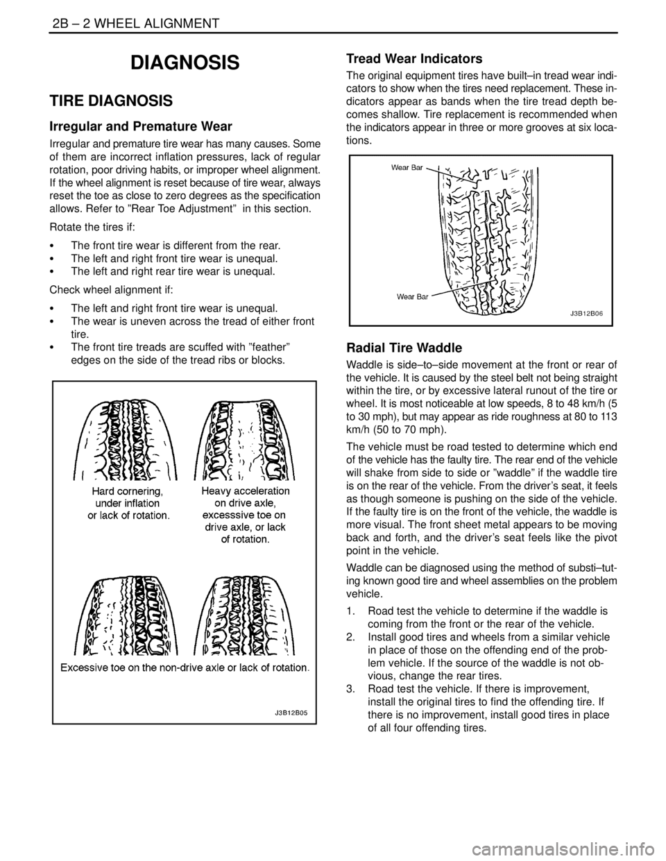
Irregular and Premature Wear
Irregular and premature tire wear has many causes. Some
of them are incorrect inflation pressures, lack of regular
rotation, poor driving habits, or improper wheel alignment.
If the wheel alignment is reset because of tire wear, always
reset the toe as close to zero degrees as the specification
allows. Refer to ”Rear Toe Adjustment” in this section.
Rotate the tires if:
S The front tire wear is different from the rear.
S The left and right front tire wear is unequal.
S The left and right rear tire wear is unequal.
Check wheel alignment if:
S The left and right front tire wear is unequal.
S The wear is uneven across the tread of either front
tire.
S The front tire treads are scuffed with ”feather”
edges on the side of the tread ribs or blocks.
Tread Wear Indicators
The original equipment tires have built–in tread wear indi-
cators to show when the tires need replacement. These in-
dicators appear as bands when the tire tread depth be-
comes shallow. Tire replacement is recommended when
the indicators appear in three or more grooves at six loca-
tions.
Radial Tire Waddle
Waddle is side–to–side movement at the front or rear of
the vehicle. It is caused by the steel belt not being straight
within the tire, or by excessive lateral runout of the tire or
wheel. It is most noticeable at low speeds, 8 to 48 km/h (5
to 30 mph), but may appear as ride roughness at 80 to 113
km/h (50 to 70 mph).
The vehicle must be road tested to determine which end
of the vehicle has the faulty tire. The rear end of the vehicle
will shake from side to side or ”waddle” if the waddle tire
is on the rear of the vehicle. From the driver’s seat, it feels
as though someone is pushing on the side of the vehicle.
If the faulty tire is on the front of the vehicle, the waddle is
more visual. The front sheet metal appears to be moving
back and forth, and the driver’s seat feels like the pivot
point in the vehicle.
Waddle can be diagnosed using the method of substi–tut-
ing known good tire and wheel assemblies on the problem
vehicle.
1. Road test the vehicle to determine if the waddle is
coming from the front or the rear of the vehicle.
2. Install good tires and wheels from a similar vehicle
in place of those on the offending end of the prob-
lem vehicle. If the source of the waddle is not ob-
vious, change the rear tires.
3. Road test the vehicle. If there is improvement,
install the original tires to find the offending tire. If
there is no improvement, install good tires in place
of all four offending tires.
Page 910 of 2643
WHEEL ALIGNMENT 2B – 3
DAEWOO V–121 BL4
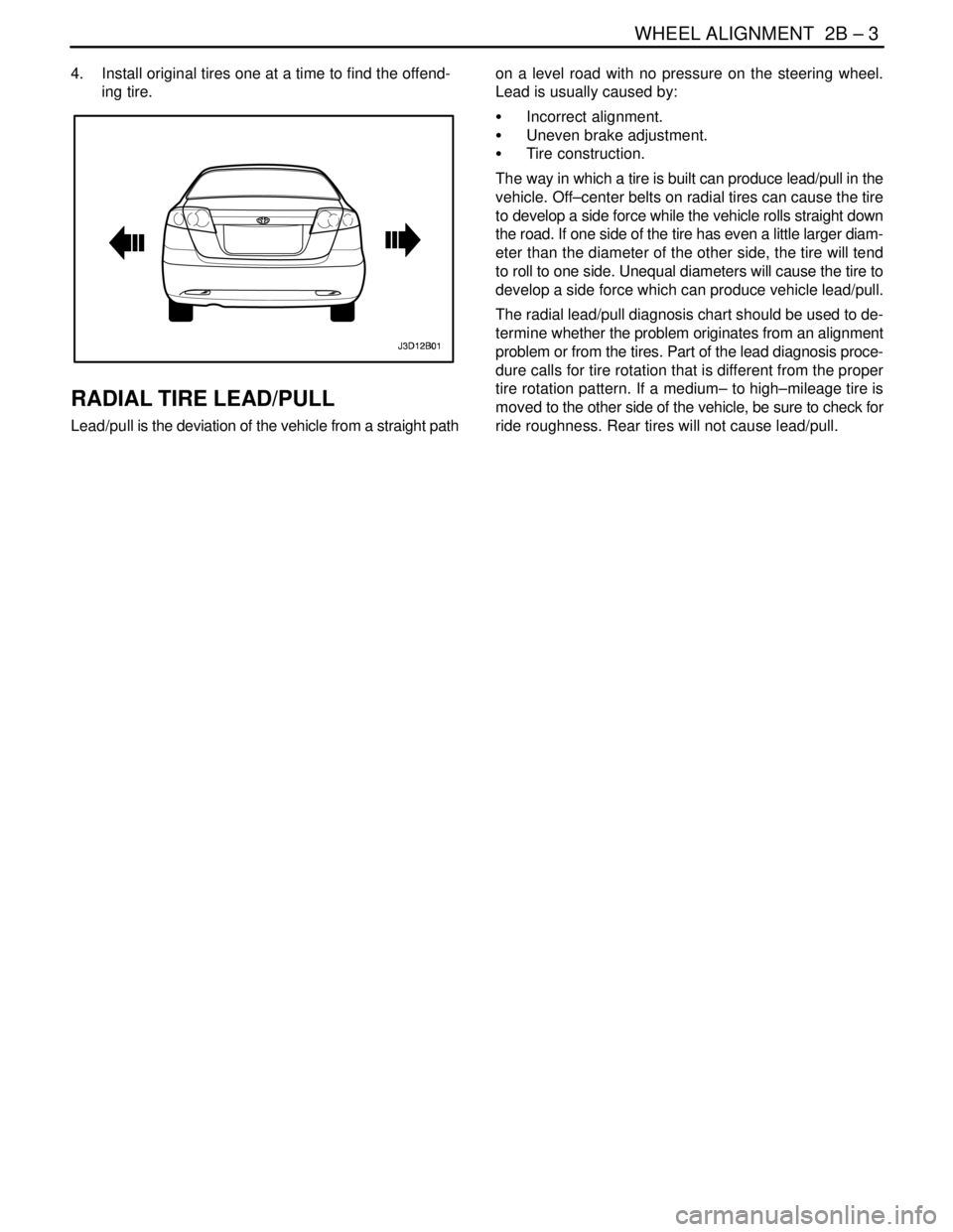
4. Install original tires one at a time to find the offend-
ing tire.
RADIAL TIRE LEAD/PULL
Lead/pull is the deviation of the vehicle from a straight pathon a level road with no pressure on the steering wheel.
Lead is usually caused by:
S Incorrect alignment.
S Uneven brake adjustment.
S Tire construction.
The way in which a tire is built can produce lead/pull in the
vehicle. Off–center belts on radial tires can cause the tire
to develop a side force while the vehicle rolls straight down
the road. If one side of the tire has even a little larger diam-
eter than the diameter of the other side, the tire will tend
to roll to one side. Unequal diameters will cause the tire to
develop a side force which can produce vehicle lead/pull.
The radial lead/pull diagnosis chart should be used to de-
termine whether the problem originates from an alignment
problem or from the tires. Part of the lead diagnosis proce-
dure calls for tire rotation that is different from the proper
tire rotation pattern. If a medium– to high–mileage tire is
moved to the other side of the vehicle, be sure to check for
ride roughness. Rear tires will not cause lead/pull.
Page 915 of 2643
2B – 8IWHEEL ALIGNMENT
DAEWOO V–121 BL4
PRELIMINARY INSPECTION
ChecksAction
Check the tires for proper inflation pressures and normal
tread wear.Inflate the tires to the proper tire pressure. Replace the
tires as needed.
Check the wheel bearings for looseness.Tighten the axle nut to the proper specification. Replace
the strut wheel bearing as needed.
Check for loose ball joints and tie rod ends.Tighten the ball joints and the tie rods.
Check the runout of the wheels and the tires.Measure and correct the tire runout.
Check the vehicle trim heights.Correct the trim heights. Make the correction before ad-
justing the toe.
Check for loose rack and pinion mounting.Tighten the mounting brackets for the rack and pinion as-
sembly.
Check for improperly operating struts.Replace the strut assembly.
Check for loose control arms.Tighten the control arm attachment bolts. Replace the con-
trol arm bushings as needed.
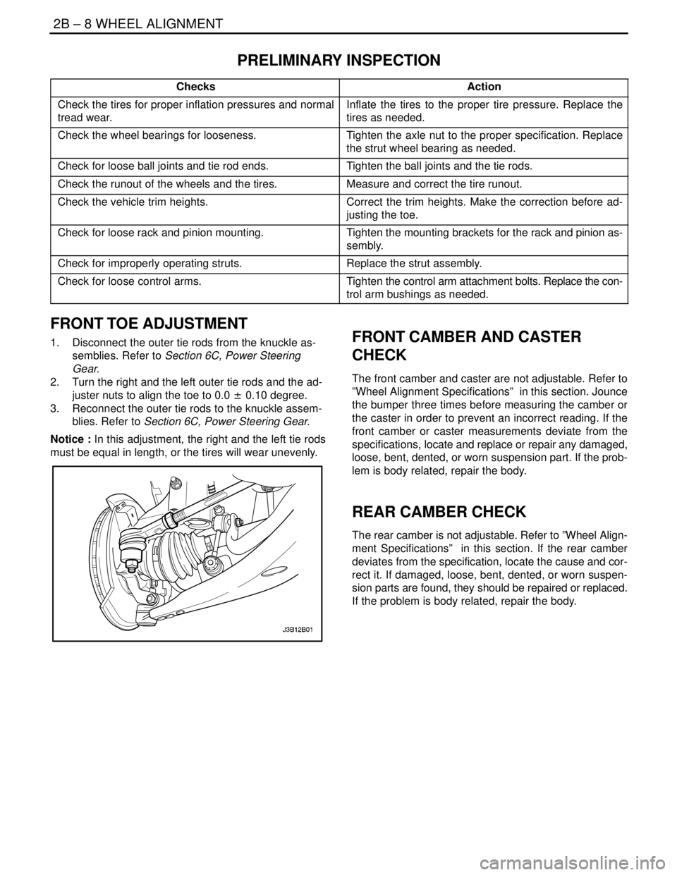
FRONT TOE ADJUSTMENT
1. Disconnect the outer tie rods from the knuckle as-
semblies. Refer to Section 6C, Power Steering
Gear.
2. Turn the right and the left outer tie rods and the ad-
juster nuts to align the toe to 0.0 ± 0.10 degree.
3. Reconnect the outer tie rods to the knuckle assem-
blies. Refer to Section 6C, Power Steering Gear.
Notice : In this adjustment, the right and the left tie rods
must be equal in length, or the tires will wear unevenly.FRONT CAMBER AND CASTER
CHECK
The front camber and caster are not adjustable. Refer to
”Wheel Alignment Specifications” in this section. Jounce
the bumper three times before measuring the camber or
the caster in order to prevent an incorrect reading. If the
front camber or caster measurements deviate from the
specifications, locate and replace or repair any damaged,
loose, bent, dented, or worn suspension part. If the prob-
lem is body related, repair the body.
REAR CAMBER CHECK
The rear camber is not adjustable. Refer to ”Wheel Align-
ment Specifications” in this section. If the rear camber
deviates from the specification, locate the cause and cor-
rect it. If damaged, loose, bent, dented, or worn suspen-
sion parts are found, they should be repaired or replaced.
If the problem is body related, repair the body.
Page 922 of 2643

FRONT SUSPENSION 2C – 5
DAEWOO V–121 BL4
DIAGNOSIS
STRUT DAMPENER
A strut dampener is basically a shock absorber. However, strut dampeners are easier to extend and retract by hand than
are shock absorbers.
Struts Seem Weak
ChecksAction
Check the tire pressures.Adjust the tire pressures to the specifications on the tire
placard.
Check the load conditions under which the vehicle is nor-
mally driven.Consult with the owner to confirm the owner’s understand-
ing of normal load conditions.
Check the compression and rebound effectiveness of the
strut dampener.Quickly push down and then lift up on the corner of the
bumper nearest the strut dampener being tested.
Compare the compression and rebound with those of a
similar vehicle that has an acceptable ride quality.
Replace the strut dampener, if needed.
Struts Are Noisy
ChecksAction
Check the mountings for looseness or damage.Tighten the strut dampener mounting nuts. Replace the
strut dampener, if needed.
Check the compression and rebound effectiveness of the
strut dampener.Quickly push down and then lift up on the corner of the
bumper nearest the strut dampener being tested.
Compare the compression and rebound with those of a
similar vehicle that has an acceptable ride quality.
Replace the strut dampener, if needed.
Leaks
ChecksAction
Check for a slight trace of fluid.The strut dampener is OK.
Check the integrity of the seal cover on the fully extended
strut.Replace the strut dampener.
Check for an excessive amount of fluid on the strut damp-
ener.Replace the strut dampener.