power DAEWOO NUBIRA 2004 Service Repair Manual
[x] Cancel search | Manufacturer: DAEWOO, Model Year: 2004, Model line: NUBIRA, Model: DAEWOO NUBIRA 2004Pages: 2643, PDF Size: 80.54 MB
Page 2458 of 2643
ROOF 9Q – 9
DAEWOO V–121 BL4
6. Remove the power sunroof control switch, if
equipped. Refer to ”Power Sunroof Control Switch”
in this section.
7. Remove the A–, B–, and C–pillar trim panels. Refer
to Section 9G, Interior Trim.
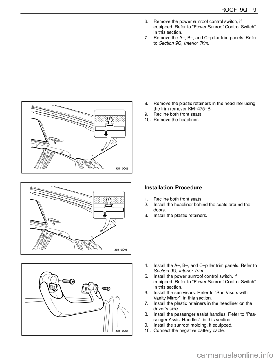
8. Remove the plastic retainers in the headliner using
the trim remover KM–475–B.
9. Recline both front seats.
10. Remove the headliner.
Installation Procedure
1. Recline both front seats.
2. Install the headliner behind the seats around the
doors.
3. Install the plastic retainers.
4. Install the A–, B–, and C–pillar trim panels. Refer to
Section 9G, Interior Trim.
5. Install the power sunroof control switch, if
equipped. Refer to ”Power Sunroof Control Switch”
in this section.
6. Install the sun visors. Refer to ”Sun Visors with
Vanity Mirror” in this section.
7. Install the plastic retainers in the headliner on the
driver’s side.
8. Install the passenger assist handles. Refer to ”Pas-
senger Assist Handles” in this section.
9. Install the sunroof molding, if equipped.
10. Connect the negative battery cable.
Page 2460 of 2643

ROOF 9Q – 11
DAEWOO V–121 BL4
POWER SUNROOF CONTROL
SWITCH
Removal Procedure
1. Disconnect the negative battery cable.
2. Pry off the interior courtesy lamp lens.
3. Remove the screws and the switch.
4. Disconnect the electrical connector.
Installation Procedure
1. Connect the electrical connector.
Notice : Dissimilar metals in direct contact with each other
may corrode rapidly. Make sure to use the correct fasten-
ers to prevent premature corrosion.
2. Install the sunroof control switch with the screws.
Tighten
Tighten the power sunroof control switch screws to 2
NSm (18 lb–in).
3. Install the interior courtesy lamp lens.
4. Connect the negative battery cable.
Page 2461 of 2643

9Q – 12IROOF
DAEWOO V–121 BL4
GENERAL DESCRIPTION
AND SYSTEM OPERATION
ROOF
The roof is a one–piece painted metal unit which incorpo-
rates a single solid headliner. There are two moldings, one
per side on the vehicle’s roof, which enclose and hide the
roof rail seams. The roof moldings are serviceable as indi-
vidual units.
The one–piece formed headliner consists of a molded
substrate covered with a foam–backed cloth facing. The
one–piece construction requires that the headliner be ser-
viced as a complete assembly.
POWER SUNROOF/SUNROOF
CONTROL SWITCH
The sunroof has the following characteristics:
S Intended to provide light and air through the roof
the vehicle.
S Built into the roof.
S Made of glass.
S Equipped with a sunshade that opens and closes
manually.
S Powered by an electric motor.
S Controlled by a toggle switch built into the interior
courtesy lamp assembly.
The sunroof control switch is a toggle button located on the
right side of the interior courtesy lamp assembly.
To operate the sunroof, the ignition must be ON.Tilting the Sunroof, Open and Closed
To tilt open the rear end of the sunroof, press and hold the
forward portion of the toggle button until the sunroof tilts
open.
To close the sunroof from a tilted–open position, press and
hold the rear portion of the toggle button until the sunroof
tilts closed.
Sliding the Sunroof, Open and Closed
To slide open the sunroof, press the rear portion of the
toggle button until the sunroof slides. If the sun shade is
closed, the sunroof will pull the sunshade open when the
sunroof slides open.
To close the sunroof from a slid–open position, press the
forward portion of the toggle button until the sunroof slides
closed.
SUN VISORS WITH VANITY MIRROR
The sun visors swing down in order to block out glare.
They also swing to the side when they are released from
the support. To replace the vanity mirror lamp, refer to
Section 9B, Lighting Systems.
PASSENGER ASSIST HANDLES
There is a passenger assist handle for each rear outboard
seat and for the front passenger seat. Passengers can use
these handles to assist in keeping their balance over rough
roads or during sharp turns.
COAT HOOKS
The coat hooks are located on the left and the right rear
passenger assist handles.
Page 2488 of 2643

REMOTE KEYLESS ENTRY AND ANTI–THEFT SYSTEM 9T1 – 7
DAEWOO V–121 BL4
REMOTE KEYLESS ENTRY
TRANSMITTER PROGRAMMING
The Remote Keyless Entry System allows for the use of
as many as four(4) transmitters for each vehicle. Replace-
ment Remote Keyless Entry System Transmitters must
first be programmend to specific vehicle using the
Scan100 Secan tool.
This process is completed using serial data communica-
tion between the Scan 100 Scan tool and the Remote Key-
less Entry Control Unit and is the only method available for
programming Transmitters.
Notice : All Transmitters for a specific vehicle must be pro-
grammed at same time.
Notice : Once the programming function of the Remote
Keyless Entry System is activated, any Transmitter(exist-
ing or new) that is not programmed(or reprogrammed)
during the programming procedure will no longer operate
the Remote Keyless Entry System of that vehicle.
Notice : Ensure that the doors, hood and trunk/rear hatch
are closed prior to starting the programming procedure.
1. Connect the Scan 100 Scan Tool to the Data Link
Connector(DLC)
2. Turn the Scan 100 Scan Tool ”ON” by pressing the
”Power” Button, then wait for the MAIN MENU
screen to be displayed.
3. From the MAIN MENU screen, select ”Diagnostics”
by pressing #1 on the Key Pad.
4. From the MODEL YEAR screen, select the ap-
propriate model year of the specific vehicle by ei-
ther scrolling down to the year and pressing ”EN-
TER”, or by pressing the respective item number on
the Key Pad.
5. From the VEHICLE TYPE screen, select the specif-
ic vehicle model by either scrolling down to the
model name and pressing ”ENTER”, or by pressing
the respective item number on the Key Pad.
6. From the SYSTEM SELECTION MENU screen,
select ”Body” by pressing #2 on the Key Pad.
7. From the BODY SELECTION MENU screen, select
”Coding” by pressing #2 on the Key Pad.8. From the CODY SELECTION MENU screen, select
”Coding” by pressing #1 on the Key Pad.
9. From the SECRET NUMBER OF CODINGS
screen, enter for(4) zero’s (0–0–0–0) in the for(4)
boxes labeled ”1–2–3–4–”.
10. From the CODING SYSTEM SELECT screen, se-
lect ”Keyless Entry” by pressing #2 on the Key Pad.
Notice : A slight delay may occur and ”PLEASE WAIT”
may be displayed before the next screen appears.
11. From the KEYLESS ENTRY CODING SYSTEM
screen, select ”Coding Transmitter” by pressing #1
on the Key Pad.
12. When directed by the Scan 100 Scan Tool, press
any Button on the first Transmitter to be pro-
grammed.
CAUTION : Ensure that Transmitters from other ve-
hicles in the immediate area are not activated during
this procedure.
13. Continue programming Transmitters when directed
by the Scan 100 Scan Tool until all Transmitters
have been programmed.
Notice : A maximum of four(4) Transmitters may be pro-
grammed to a vehicle.
14. Once all Transmitters have been programmed,
press the ”ESC” Button on the Key Pad. The dis-
play will confirm the number of Transmitters pro-
grammed. If the number displayed does not match
the number of Transmitters programmed, repeat
the procedure.
15. Turn the Scan 100 Scan Tool ”OFF” by pressing the
”POWER” Button, then disconnect it from the Data
Link Connector.
16. Wait approximately 10 seconds, then test the op-
eration of each programmed Transmitter to ensure
it operates properly.
The control module/receiver leaves the programming
mode automatically and switches to the normal operating
mode when either of the following conditions occurs:
S the scan tool is disconnected from the ALDL.
S Four passwords are recorded in the control module/
receiver.
Page 2495 of 2643

IMMOBILIZER ANTI–THEFT SYSTEM 9T2 – 5
DAEWOO V–121 BL4
P1626, 1628 – ECM Immobilizer Error
(No Successful Communication)
StepActionValue(s)YesNo
1Connect the scan tool using the following procedure:
1. Insert the cartridge into the scan tool.
2. Turn the ignition switch to the OFF position.
3. Connect the scan tool to the data link connec-
tor (DLC).
4. Connect the scan tool’s power cord to the cigar
lighter socket.
5. Select immobilizer mode on the scan tool.
6. Turn the ignition ON, but do not start the en-
gine.
Is communication established between the scan tool
and the immobilizer control unit?–Go to Step 2Go to ”Commu-
nication Be-
tween Immobi-
lizer and Test
Equipment”
2Read the IMMO & ECM ID CODE message that was
displayed after requesting DIAGNOSIS.
Did the message differ from normal message?
Normal Message –
ECM MODE: LEARNT
IMMO. MODE: LEARNT
VIN CODE: SAME–Go to ”Identifi-
cation (ID)
Code Repro–
gramming”Go to Step 3
3Check for an open serial data wire between the im-
mobilizer control unit and the ECM.
Was the circuit open?–Go to Step 4Go to Step 5
4Repair the open serial data wire between the ECM
and the immobilizer control unit.
Is the repair complete?–System OK–
51. Replace the immobilizer.
2. Reprogram the identification (ID) code. Refer
to ”Identification (ID) Code Reprogramming” in
this section.
Is the repair complete?–System OKGo to Step 6
61. Replace the ECM.
2. Turn the ignition ON, OFF for more than 4 sec-
onds.
3. Turn the ignition ON.
Is the repair complete?–System OK–
Page 2497 of 2643

IMMOBILIZER ANTI–THEFT SYSTEM 9T2 – 7
DAEWOO V–121 BL4
P1631, 1629 – ECM Immobilizer Error (Incorrect Answer)
StepActionValue(s)YesNo
1Connect the scan tool using the following procedure:
1. Insert the cartridge into the scan tool.
2. Turn the ignition switch to the OFF.
3. Connect the scan tool to the data link connec-
tor (DLC).
4. Connect the scan tool’s power cord to the cigar
lighter socket.
5. Turn the ignition ON, but do not start the en-
gine.
Is communication established between the scan tool
and the immobilizer control unit?–Go to Step 2Go to ”Commu-
nication Be-
tween Immobi-
lizer and Test
Equipment”
21. Select DIAGNOSIS from the scan tool menu.
2. Read the IMMO & ECM ID CODE (immobiliza-
tion and electronic control module identification
code) message.
Did the message differ from normal message?
Normal Message –
ECM MODE:LEARNT
IMMO. MODE: LEARNT
VIN CODE: SAME–Go to ”Identifi-
cation (ID)
Code Repro–
gramming”Go to Step 3
31. Replace the ECM.
2. Reprogram the ID code.
Is the repair complete?–System OKGo to Step 4
41. Replace the ECM.
2. Turn the ignition ON, OFF for more than 4 sec-
onds.
3. Turn the ignition ON.
Is the repair complete?–System OK–
Page 2501 of 2643

IMMOBILIZER ANTI–THEFT SYSTEM 9T2 – 11
DAEWOO V–121 BL4
GENERAL DESCRIPTION
AND SYSTEM OPERATION
IMMOBILIZER SYSTEM
The purpose of the Immobilizer system is to provide addi-
tional theft deterrence to the vehicle in which it is installed
and to prevent it from being stolen or driven by unautho-
rized users.
The verification of the user authorization is done by an igni-
tion key with integrated transponder.
The external LED displays the Immobilizer status and has
an additional theft deterrence function.
To secure the communication, the status is exchanged be-
tween the Immobilizer and the ECM in a 5 byte of encoded
data.
These 5 bytes are composed by a mixture of random data
and two types of fixed code
S a vehicle model identification number : MIN
S a vehicle specific identification : VIN
The MIN is known from the first supply of the system.
The VIN is realized by ICU on the special order from the
key coding (reading of transponder code and storing it as
valid key code in Immobilizer EEPROM).
A different random data is computed at each key transi-
tion.
All the immobilization communication between the ECM
and ICU is made on K–line (K line : Serial data line ’7’).
Due to the learning of the Vehicle specific identification
Number, both ICU and ECM can stay in 3 stable modes
S Virgin mode (VIN not learnt)
S Learnt mode (VIN learnt)
S Neutral mode (for a new VIN learning)
In case of using valid key, the release message commu-
nication with the ECM take place and the LED displays the
Immobilizer status valid key In case of using invalid key,
the ECM disables the fuel injector circuit with coded inter-
vention and sets DTC(Diagnostic Trouble Code)
The above conditions are maintained until the ignition is
switched off.
An ECM without an immobilizer control unit cannot be in-
terchanged for an ECM that is used with an immobilizer
control unit system. The Immobilizer control unit and ECM
must have a matching ID code. ID coding and key coding
are accomplished by using Scanner–100
The Immobilizer system consists of
S a maximum or 5 ignition keys with integrated trans-
ponder
S the toroidal coil (Detection coil) for energizing and
reading the transponder mounted at the ignition
lock.S the Immobilizer control unit(ICU) with :
– power supply
– ignition input circuit
– transponder modulation and demodulation unit
– EEPROM
– driver electronic for the external status LED
– serial data link hardware
S the external status LED for displaying the Immobi-
lizer status
S the serial data link between Immobilizer and ECM
ELECTRONICALLY CODED KEYS
Each valid ignition key has an internal transponder which
is a read /write transponder.
The transponder contains an implementation of a crypto–
algorithm with 96 bits of user configurable s cret–key con-
tained in EEPROM and transmits data to the ICU by mod-
ulating the amplitude of the ele tromagnetic field, and
receives data and commands in a similar way.
DETECTION COIL
The toroidal coil is mounted at the ignition lock in front of
the key barrel.
It is connected to the ICU with a four terminal connector
fixed at the body of the coil.
The length of the connection between coil and Immobilizer
is restricted to 50cm. The correct placement on the ignition
lock and the exact electrical data is very important for the
reading distance of transponder.
he toroidal coil and receiving coil inside the transponder
built a transformer. During the readingprocess the coil in-
duces energy into the transponder. The transponder
charges the field and generates an amplitude modulated
signal with the manchester coded data. This charge of the
field is demodulated inside the Immobilizer.
The Immobilizer contains the coil driver hardware for di-
rect connection of the toroidal coil.
IMMOBILIZER CONTROL UNIT
The function of the Immobilizer System is shared between
the ICU and the ECM.
The task of the Immobilizer Electronic Control unit (ICU)
are:
S Reading of the input information ”ignition ON/OFF”
S Controlling the states LED
S Controlling the transponder read/write process
(modulation, demodulation, decoding, comparison
of the read code with the code of the valid keys).
S Communication with the ECM after ignition ON (re-
ceiving of the ECM–request and transmission of
release message).
S Special functions for calculation and handling of the
VIN–code.
The VIN code is calculated by the Immobilizer using a ran-
dom generator.
Page 2502 of 2643

9T2 – 12IIMMOBILIZER ANTI–THEFT SYSTEM
DAEWOO V–121 BL4
The VIN code is transmitted from the Immobilizer in the re-
lease message communication only incase of using an au-
thorized key. Without an authorized key it is not possible
to getthe system VIN code.In case of ECM internal state
is in Virgin mode or neutral mode the ECM learns the sys-
tem VIN code automatically after receiving the first release
response message.
To get a synchronized Immobilizer system (same VIN–
code in Immobilizer and ECM,authorized key) the DLC
test equipment has to be used for authorization of the
keys(first key coding). The usage of this test equipment is
restricted to authorized persons.
S Communication with the DLC–test equipment. Main
functions are the key coding procedure, the VIN–
code handling and the support for system test func-
tions.
S Handling of the software watchdog
Operation
In the active mode of immobilizer (engine OFF, IG key
OFF) the status LED isblinking as mode A. When ignition
is turned ON, the system wakes up and tries to read out
the transponder.
In case of the detection of a valid key , The release mes-
sage communication with the ECM takes place. The sta-
tus LED displays the Immobilizer state ”valid key”.
After turning off the ignition(ignition OFF detection similar
to the ECM ignition OFF detection), the Immobilizer
changes to the active mode. The status LED is blinking as
Mode A.
Data Link Connector (DLC) Mode
When the ignition is on, a scan tool can switch the immobi-
lizer control unit to the DLC mode for diagnostics, key cod-
ing and ID coding.
S The status LED is turned off during DLC–mode
S The Immobilizer will answer all correct messages,
which are defined as Immobilizer messages.
ID Code Handling
One of 65,535 VIN codes is stored in the immobilizer EE-
PROM.
The VIN code can be erased by using ”Reset VIN code”
command of the scan tool.
When the immobilizer control unit calculates a new VIN
code, ECM VIN code should be reset to get identical with
the immobilizer control unit’s.
During diagnostic procedures, the VIN code can be read
for comparison with the ECM VIN code by using the scan
tool’s ”Read immobilizer control unit VIN code” command.
SERIAL DATA LINK
Serial data can be exchanged between a scan tool and the
ECM and the Immobilizer control unit.
ELECTRONIC CONTROL MOUDLE
(ECM)
S ECM in Virgin mode
In this mode, the ECM knows only the model
vehicle identifier code.
The engine can be locked/unlocked.
ECM requests to ICU the VIN number. As soon
as the ECM receives two correct consecutive
communication frames with the same VIN code
the ECM learns it.
The VIN code will be stored in non–volatile
memory at the end of power latch phase. ECM
enters in Learnt mode.
S ECM in Learnt mode
In such a state, ECM checks on every commu-
nication, the correct encoding of the ICU.
If the code received is not correct, then the vehicle is im-
mobilized.
The coded 5 bytes of data emitted by ECM are
a mixture of MIN code and random.
The coded 5 bytes of data emitted by ICU are a
mixture of VIN code and random.
S ECM in Neutral mode
This mode is a special intermediate mode, used
for ICU replacement or immobilizer option instal-
lation.
ECM request to ICU the VIN number. As soon
as the ECM receives two correct consecutive
communication frames with the same VIN code
the ECM learns it. The VIN code will be stored
in non–volatile memory at the end of power latch
phase. ECM enters in Learnt mode.
S After turning on the ignition the ECM will control the
engine in a normal way for starting and running
while waiting for a valid release response message
from the Immobilizer.