remote control DAEWOO NUBIRA 2004 Service Repair Manual
[x] Cancel search | Manufacturer: DAEWOO, Model Year: 2004, Model line: NUBIRA, Model: DAEWOO NUBIRA 2004Pages: 2643, PDF Size: 80.54 MB
Page 5 of 2643

v
TABLE OF CONTENTS
Section 0B General Information
Section 1 Engine
Section 1A General Engine Information
Section 1C1 1.4L/1.6L DOHC Engine Mechanical
Section 1C2 1.8L DOHC Engine Mechanical
Section 1D Engine Cooling
Section 1E Engine Electrical
Section 1F Engine Controls
Section 1G Engine Exhaust
Section 2 Suspension
Section 2A Suspension Diagnosis
Section 2B Wheel Alignment
Section 2C Front Suspension
Section 2D Rear Suspension
Section 2E Tires and Wheels
Section 3 Driveline/Axle
Section 3A Automatic Transaxle Drive Axle
Section 3B Manual Transaxle Drive Axle
Section 4 Brakes
Section 4A Hydraulic Brakes
Section 4B Master Cylinder
Section 4C Power Booster
Section 4D Front Disc Brakes
Section 4E1 Rear Disc Brakes
Section 4E2 Rear Drum Brakes
Section 4F Antilock Brake System
Section 4G Parking Brake
Section 5 Transmission/Transaxle
Section 5A1 ZF 4HP16 Automatic Transaxle
Section 5A2 AISIN Automatic Transaxle
Section 5B Five-Speed Manual Transaxle
Section 5C Clutch
Section 6 Steering
Section 6A Power Steering System
Section 6B Power Steering PumpSection 6C Power Steering Gear
Section 6E Steering Wheel and Column
Section 7 Heating, Ventilation, and Air
Conditioning (HVAC)
Section 7A Heating and Ventilation System
Section 7B Manual Control Heating, Ventilation,
and Air Conditioning System
Section 7D Automatic Temperature Control HVAC
Section 8 Restraints
Section 8A Seat Belts
Section 8B Supplemental Inflatable Restraints
(SIR)
Section 9 Body and Accessories
Section 9A Body Wiring System
Section 9B Lighting Systems
Section 9C Horns
Section 9D Wipers/Washer Systems
Section 9E Instrumentation/Driver Information
Section 9F Audio Systems
Section 9G Interior Trim
Section 9H Seats
Section 9I Waterleaks
Section 9J Windnoise
Section 9K Squeaks and Rattles
Section 9L Glass and Mirrors
Section 9M Exterior Trim
Section 9N Frame and Underbody
Section 9O Bumpers and Fascias
Section 9P Doors
Section 9Q Roof
Section 9R Body Front End
Section 9S Body Rear End
Section 9T1 Remote Keyless Entry and Anti–Theft
System
Section 9T2 Immobilizer Anti–Theft System
Page 2206 of 2643
8B – 102ISUPPLEMENTAL INFLATABLE RESTRAINTS (SIR)
DAEWOO V–121 BL4
spring should never be disassembled, and there is no
timekeeping function. The clock spring contains two or
three current–carrying coils. One of the current–carrying
coils maintains continuous contact within the driver de-
ployment loop while the steering wheel is rotated. The
clock spring also contains coils that maintain continuous
contact for horn and remote audio control switch circuit.
Turning the steering wheel in one direction tightens the
coil, and turning the steering wheel in the opposite direc-
tion loosens the coil. Do not turn the clock spring when the
steering wheel is not attached. Refer to ”Clock Spring” in
this section for proper installation of the clock spring.
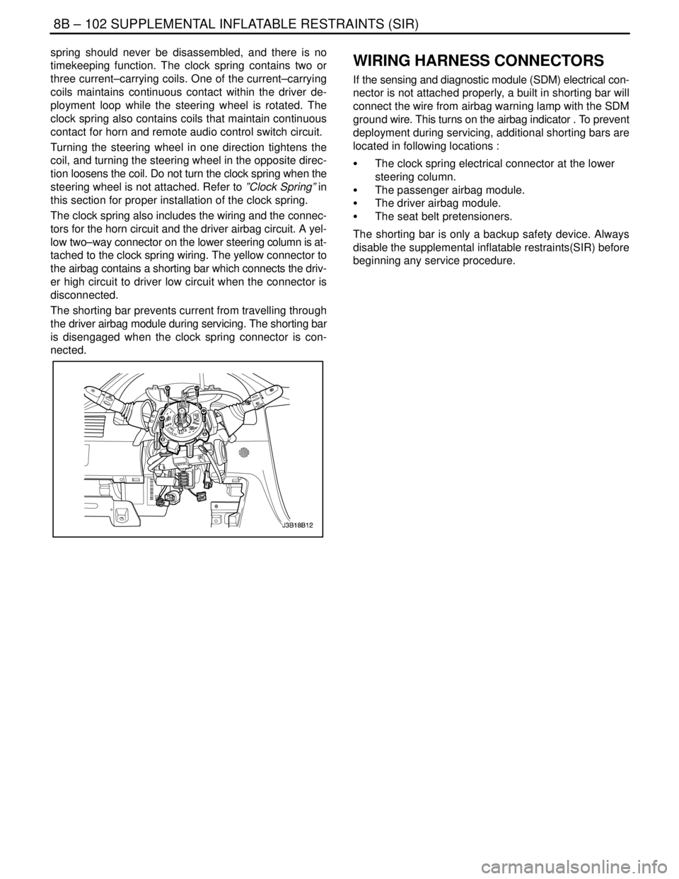
The clock spring also includes the wiring and the connec-
tors for the horn circuit and the driver airbag circuit. A yel-
low two–way connector on the lower steering column is at-
tached to the clock spring wiring. The yellow connector to
the airbag contains a shorting bar which connects the driv-
er high circuit to driver low circuit when the connector is
disconnected.
The shorting bar prevents current from travelling through
the driver airbag module during servicing. The shorting bar
is disengaged when the clock spring connector is con-
nected.WIRING HARNESS CONNECTORS
If the sensing and diagnostic module (SDM) electrical con-
nector is not attached properly, a built in shorting bar will
connect the wire from airbag warning lamp with the SDM
ground wire. This turns on the airbag indicator . To prevent
deployment during servicing, additional shorting bars are
located in following locations :
S The clock spring electrical connector at the lower
steering column.
S The passenger airbag module.
S The driver airbag module.
S The seat belt pretensioners.
The shorting bar is only a backup safety device. Always
disable the supplemental inflatable restraints(SIR) before
beginning any service procedure.
Page 2330 of 2643

SECTION : 9F
AUDIO SYSTEMS
CAUTION : Disconnect the negative battery cable before removing or installing any electrical unit or when a tool
or equipment could easily come in contact with exposed electrical terminals. Disconnecting this cable will help
prevent personal injury and damage to the vehicle. The ignition must also be in LOCK unless otherwise noted.
TABLE OF CONTENTS
SPECIFICATIONS9F–1 . . . . . . . . . . . . . . . . . . . . . . . . . .
Fastener Tightening Specifications 9F–1. . . . . . . . . . .
SCHEMATIC AND ROUTING DIAGRAMS9F–2 . . . . .
Audio System Circuit 9F–2. . . . . . . . . . . . . . . . . . . . . . .
DIAGNOSIS9F–3 . . . . . . . . . . . . . . . . . . . . . . . . . . . . . . . .
Stereo Cassette AM/FM Radio 9F–3. . . . . . . . . . . . . .
Speakers 9F–5. . . . . . . . . . . . . . . . . . . . . . . . . . . . . . . . .
MAINTENANCE AND REPAIR9F–7 . . . . . . . . . . . . . . .
ON–VEHICLE SERVICE 9F–7. . . . . . . . . . . . . . . . . . . . .
Stereo Cassette AM/FM Radio 9F–7. . . . . . . . . . . . . .
Audio Remote Controller 9F–7. . . . . . . . . . . . . . . . . . . . Notchback CD Changer 9F–8. . . . . . . . . . . . . . . . . . . .
Door Speakers 9F–8. . . . . . . . . . . . . . . . . . . . . . . . . . . .
Tweeter Speakers 9F–9. . . . . . . . . . . . . . . . . . . . . . . . .
Glass Antenna Module 9F–9. . . . . . . . . . . . . . . . . . . . .
Hatchback Windshield Antenna Module 9F–10. . . . . .
GENERAL DESCRIPTION AND SYSTEM
OPERATION9F–11 . . . . . . . . . . . . . . . . . . . . . . . . . . . . . .
Stereo Cassette AM/FM Radio 9F–11. . . . . . . . . . . . . .
Audio Scurity System 9F–11. . . . . . . . . . . . . . . . . . . . . .
Speakers 9F–11. . . . . . . . . . . . . . . . . . . . . . . . . . . . . . . . .
Tape Player and Cassette Care 9F–11. . . . . . . . . . . . . .
Compact Disc Care 9F–11. . . . . . . . . . . . . . . . . . . . . . . .
SPECIFICATIONS
FASTENER TIGHTENING SPECIFICATIONS
ApplicationNSmLb–FtLb–In
Door Speaker Screws2–18
Rear Speaker Screws2–18
Glass Antenna Screws2–18
Page 2336 of 2643
AUDIO SYSTEMS 9F – 7
DAEWOO V–121 BL4
MAINTENANCE AND REPAIR
ON–VEHICLE SERVICE
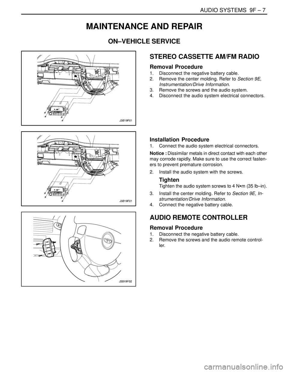
STEREO CASSETTE AM/FM RADIO
Removal Procedure
1. Disconnect the negative battery cable.
2. Remove the center molding. Refer to Section 9E,
Instrumentation/Drive Information.
3. Remove the screws and the audio system.
4. Disconnect the audio system electrical connectors.
Installation Procedure
1. Connect the audio system electrical connectors.
Notice : Dissimilar metals in direct contact with each other
may corrode rapidly. Make sure to use the correct fasten-
ers to prevent premature corrosion.
2. Install the audio system with the screws.
Tighten
Tighten the audio system screws to 4 NSm (35 lb–in).
3. Install the center molding. Refer to Section 9E, In-
strumentation/Drive Information.
4. Connect the negative battery cable.
AUDIO REMOTE CONTROLLER
Removal Procedure
1. Disconnect the negative battery cable.
2. Remove the screws and the audio remote control-
ler.
Page 2337 of 2643
9F – 8IAUDIO SYSTEMS
DAEWOO V–121 BL4
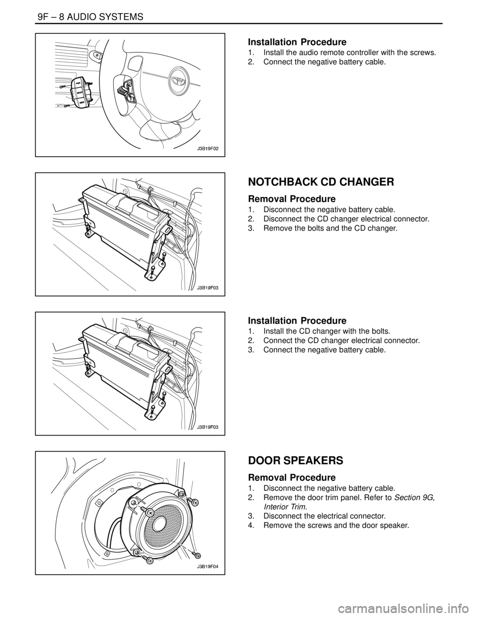
Installation Procedure
1. Install the audio remote controller with the screws.
2. Connect the negative battery cable.
NOTCHBACK CD CHANGER
Removal Procedure
1. Disconnect the negative battery cable.
2. Disconnect the CD changer electrical connector.
3. Remove the bolts and the CD changer.
Installation Procedure
1. Install the CD changer with the bolts.
2. Connect the CD changer electrical connector.
3. Connect the negative battery cable.
DOOR SPEAKERS
Removal Procedure
1. Disconnect the negative battery cable.
2. Remove the door trim panel. Refer to Section 9G,
Interior Trim.
3. Disconnect the electrical connector.
4. Remove the screws and the door speaker.
Page 2343 of 2643
INTERIOR TRIM 9G – 3
DAEWOO V–121 BL4
MAINTENANCE AND REPAIR
ON–VEHICLE SERVICE
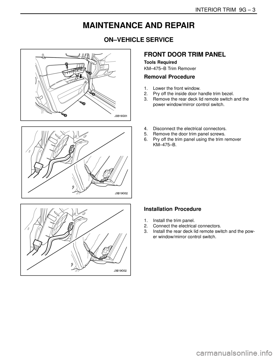
FRONT DOOR TRIM PANEL
Tools Required
KM–475–B Trim Remover
Removal Procedure
1. Lower the front window.
2. Pry off the inside door handle trim bezel.
3. Remove the rear deck lid remote switch and the
power window/mirror control switch.
4. Disconnect the electrical connectors.
5. Remove the door trim panel screws.
6. Pry off the trim panel using the trim remover
KM–475–B.
Installation Procedure
1. Install the trim panel.
2. Connect the electrical connectors.
3. Install the rear deck lid remote switch and the pow-
er window/mirror control switch.
Page 2482 of 2643

SECTION : 9T1
REMOTE KEYLESS ENTRY AND ANTI–THEFT
SYSTEM
CAUTION : Disconnect the negative battery cable before removing or installing any electrical unit or when a tool
or equipment could easily come in contact with exposed electrical terminals. Disconnecting this cable will help
prevent personal injury and damage to the vehicle. The ignition must also be in LOCK unless otherwise noted.
TABLE OF CONTENTS
SPECIFICATIONS 9T1–1 . . . . . . . . . . . . . . . . . . . . . . . . .
Fastener Tightening Specifications 9T1–1. . . . . . . . . .
SCHEMATIC AND ROUTING DIAGRAMS9T1–2 . . . .
Notchback Remote Keyless Entry and Anti–Theft
System 9T1–2. . . . . . . . . . . . . . . . . . . . . . . . . . . . . . . .
Hatchback Remote Keyless Entry and Anti–Theft
System 9T1–3. . . . . . . . . . . . . . . . . . . . . . . . . . . . . . . .
Control Module/Receiver Connector 9T1–4. . . . . . . . .
MAINTENANCE AND REPAIR9T1–5 . . . . . . . . . . . . . .
ON–VEHICLE SERVICE 9T1–5. . . . . . . . . . . . . . . . . . . .
Control Module/Receiver 9T1–5. . . . . . . . . . . . . . . . . . .
Siren (General Only) 9T1–5. . . . . . . . . . . . . . . . . . . . . . Remote Keyless Entry Transmitter
Programming 9T1–7. . . . . . . . . . . . . . . . . . . . . . . . . . .
GENERAL DESCRIPTION AND SYSTEM
OPERATION9T1–8 . . . . . . . . . . . . . . . . . . . . . . . . . . . . .
Remote Keyless Entry and Anti–Theft System 9T1–8
Remote Locking and Unlocking 9T1–8. . . . . . . . . . . . .
Security Indicator 9T1–8. . . . . . . . . . . . . . . . . . . . . . . . .
Intrusion Sensing 9T1–8. . . . . . . . . . . . . . . . . . . . . . . . .
Siren (General Only) 9T1–8. . . . . . . . . . . . . . . . . . . . . .
Vehicle Locator 9T1–8. . . . . . . . . . . . . . . . . . . . . . . . . . .
Autolocking (Safety Lock) 9T1–9. . . . . . . . . . . . . . . . . .
Control Module/Receiver 9T1–9. . . . . . . . . . . . . . . . . . .
Fault or Alarm Indication 9T1–9. . . . . . . . . . . . . . . . . . .
SPECIFICATIONS
FASTENER TIGHTENING SPECIFICATIONS
ApplicationNSmLb–FtLb–In
Siren Braket Mounting Bolts.8–71
Page 2485 of 2643

9T1 – 4IREMOTE KEYLESS ENTRY AND ANTI–THEFT SYSTEM
DAEWOO V–121 BL4
CONTROL MODULE/RECEIVER CONNECTOR
TerminalColorDescription
1YELSiren
2BLKGround
3––
4LT BLUDoor and Trunk Tamper Switch
5PNK/BLKTrunk Open Switch
6––
7PNK/DKBLUHood Open Switch
8PPLDoor contact Switch
9LT BLU/BLKUnlock
10LT GRN/WHTLock
11YELUnlock
12LT GRNAnti–Theft Door Locking Switch
13DK BLURight Turn Signal Bulb
14––
15PNKIgnition+
16––
17LT GRNDiagnostic Communication
18LT GRN/REDKey Reminder Switch
19YEL/DK GRNSecurity Indicator
20PPLAnti–Theft Door Locking Switch
21––
22––
23––
24BRNTrunk Open Switch
25ORNBattery+
26LT BLULeft Turn Signal Bulb
Page 2486 of 2643
REMOTE KEYLESS ENTRY AND ANTI–THEFT SYSTEM 9T1 – 5
DAEWOO V–121 BL4
MAINTENANCE AND REPAIR
ON–VEHICLE SERVICE
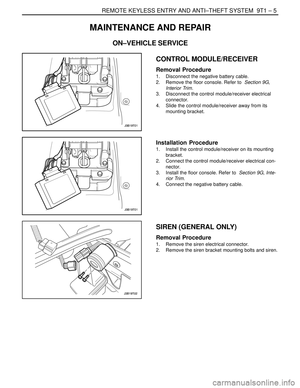
CONTROL MODULE/RECEIVER
Removal Procedure
1. Disconnect the negative battery cable.
2. Remove the floor console. Refer to Section 9G,
Interior Trim.
3. Disconnect the control module/receiver electrical
connector.
4. Slide the control module/receiver away from its
mounting bracket.
Installation Procedure
1. Install the control module/receiver on its mounting
bracket.
2. Connect the control module/receiver electrical con-
nector.
3. Install the floor console. Refer to Section 9G, Inte-
rior Trim.
4. Connect the negative battery cable.
SIREN (GENERAL ONLY)
Removal Procedure
1. Remove the siren electrical connector.
2. Remove the siren bracket mounting bolts and siren.
Page 2488 of 2643

REMOTE KEYLESS ENTRY AND ANTI–THEFT SYSTEM 9T1 – 7
DAEWOO V–121 BL4
REMOTE KEYLESS ENTRY
TRANSMITTER PROGRAMMING
The Remote Keyless Entry System allows for the use of
as many as four(4) transmitters for each vehicle. Replace-
ment Remote Keyless Entry System Transmitters must
first be programmend to specific vehicle using the
Scan100 Secan tool.
This process is completed using serial data communica-
tion between the Scan 100 Scan tool and the Remote Key-
less Entry Control Unit and is the only method available for
programming Transmitters.
Notice : All Transmitters for a specific vehicle must be pro-
grammed at same time.
Notice : Once the programming function of the Remote
Keyless Entry System is activated, any Transmitter(exist-
ing or new) that is not programmed(or reprogrammed)
during the programming procedure will no longer operate
the Remote Keyless Entry System of that vehicle.
Notice : Ensure that the doors, hood and trunk/rear hatch
are closed prior to starting the programming procedure.
1. Connect the Scan 100 Scan Tool to the Data Link
Connector(DLC)
2. Turn the Scan 100 Scan Tool ”ON” by pressing the
”Power” Button, then wait for the MAIN MENU
screen to be displayed.
3. From the MAIN MENU screen, select ”Diagnostics”
by pressing #1 on the Key Pad.
4. From the MODEL YEAR screen, select the ap-
propriate model year of the specific vehicle by ei-
ther scrolling down to the year and pressing ”EN-
TER”, or by pressing the respective item number on
the Key Pad.
5. From the VEHICLE TYPE screen, select the specif-
ic vehicle model by either scrolling down to the
model name and pressing ”ENTER”, or by pressing
the respective item number on the Key Pad.
6. From the SYSTEM SELECTION MENU screen,
select ”Body” by pressing #2 on the Key Pad.
7. From the BODY SELECTION MENU screen, select
”Coding” by pressing #2 on the Key Pad.8. From the CODY SELECTION MENU screen, select
”Coding” by pressing #1 on the Key Pad.
9. From the SECRET NUMBER OF CODINGS
screen, enter for(4) zero’s (0–0–0–0) in the for(4)
boxes labeled ”1–2–3–4–”.
10. From the CODING SYSTEM SELECT screen, se-
lect ”Keyless Entry” by pressing #2 on the Key Pad.
Notice : A slight delay may occur and ”PLEASE WAIT”
may be displayed before the next screen appears.
11. From the KEYLESS ENTRY CODING SYSTEM
screen, select ”Coding Transmitter” by pressing #1
on the Key Pad.
12. When directed by the Scan 100 Scan Tool, press
any Button on the first Transmitter to be pro-
grammed.
CAUTION : Ensure that Transmitters from other ve-
hicles in the immediate area are not activated during
this procedure.
13. Continue programming Transmitters when directed
by the Scan 100 Scan Tool until all Transmitters
have been programmed.
Notice : A maximum of four(4) Transmitters may be pro-
grammed to a vehicle.
14. Once all Transmitters have been programmed,
press the ”ESC” Button on the Key Pad. The dis-
play will confirm the number of Transmitters pro-
grammed. If the number displayed does not match
the number of Transmitters programmed, repeat
the procedure.
15. Turn the Scan 100 Scan Tool ”OFF” by pressing the
”POWER” Button, then disconnect it from the Data
Link Connector.
16. Wait approximately 10 seconds, then test the op-
eration of each programmed Transmitter to ensure
it operates properly.
The control module/receiver leaves the programming
mode automatically and switches to the normal operating
mode when either of the following conditions occurs:
S the scan tool is disconnected from the ALDL.
S Four passwords are recorded in the control module/
receiver.