drain bolt DATSUN 210 1979 User Guide
[x] Cancel search | Manufacturer: DATSUN, Model Year: 1979, Model line: 210, Model: DATSUN 210 1979Pages: 548, PDF Size: 28.66 MB
Page 231 of 548
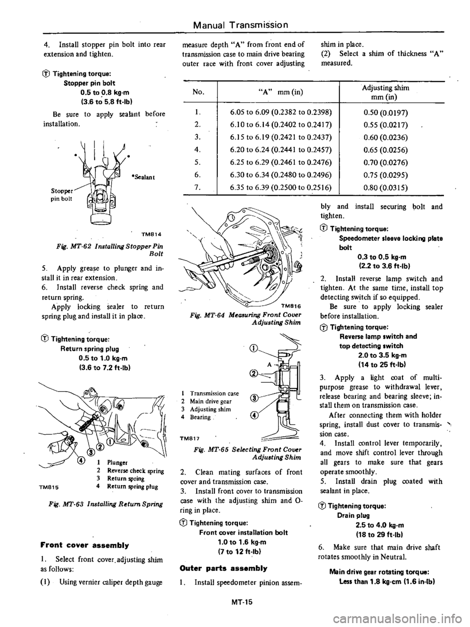
4
Install
stopper
pin
bolt
into
rear
extension
and
tighten
l
J
Tightening
torque
Stopper
pin
bolt
0
5
to
0
8
kg
m
3
6
to
5
8
ft
lb
Be
sure
to
apply
sealant
before
installation
Stopper
pin
bolt
Sealant
TM814
Fig
MT
62
Installing
Stopper
Pin
Bolt
5
Apply
grease
to
plunger
and
in
stall
it
in
rear
extension
6
Install
reverse
check
spring
and
return
spring
Apply
locking
sealer
to
return
spring
plug
and
install
it
in
place
l
J
Tightening
torque
Return
spring
plug
0
5
to
1
0
kg
m
3
6
to
7
2
ft
lb
TM815
Plunger
Reverse
check
spring
Return
spring
Return
spring
plug
Fig
MT
63
Installing
Return
Spring
Front
cover
assembly
1
Select
front
cover
adjusting
shim
as
follows
I
Using
vernier
caliper
depth
gauge
Manual
Transmission
measure
depth
A
from
front
end
of
transmission
case
to
main
drive
bearing
outer
race
with
front
cover
adjusting
No
A
mm
in
I
2
3
4
5
6
7
shim
in
place
2
Select
a
shim
of
thickness
A
measured
Adjusting
shim
mm
in
6
05
to
6
09
0
2382
to
0
2398
6
10
to
6
14
0
2402
to
0
2417
6
15
to
6
19
0
2421
to
0
2437
6
20
to
6
24
0
2441
to
0
2457
6
25
to
6
29
0
2461
to
0
2476
6
30
to
6
34
0
2480
to
0
2496
6
35
to
6
39
0
2500
to
0
2516
0
50
0
0197
0
55
0
0217
0
60
0
0236
0
65
0
0256
0
70
0
0276
0
75
0
0295
0
80
0
0315
TM816
Fig
MT
64
Meaauring
Front
Cover
Adjusting
Shim
CD
1
Transmission
case
2
Main
drive
gear
3
Adjusting
shim
4
Bearing
TM817
Fig
MT
65
Selecting
Front
Co
r
Adju
ting
Shim
2
Clean
mating
surfaces
of
front
cover
and
transmission
case
3
Install
front
cover
to
transmission
case
with
the
adjusting
shim
and
0
ring
in
place
l
J
Tightening
torque
Front
cover
installation
bolt
1
0
to
1
6
kg
m
7
to
12
ft
Ib
Outer
parts
assembly
Install
speedometer
pinion
assem
MT15
bly
and
install
securing
bolt
and
tighten
l
J
Tightening
torque
Speedometer
Ieeve
locking
plate
bolt
0
3
to
0
5
kg
m
2
2
to
3
6
ft
Ib
2
Install
reverse
lamp
switch
and
tighten
At
the
same
time
install
top
detecting
switch
if
so
equipped
Be
sure
to
apply
locking
sealer
before
installation
l
J
Tightening
torque
Revene
lamp
switch
and
top
detecting
switch
2
0
to
3
5
kg
m
14
to
25
ft
Ib
3
Apply
a
light
coat
of
multi
purpose
grease
to
withdrawal
lever
release
bearing
and
bearing
sleeve
in
stall
them
on
transmission
case
After
connecting
them
with
holder
spring
install
dust
cover
to
transmis
sian
case
4
Install
control
lever
temporarily
and
move
shift
control
lever
through
all
gears
to
make
sure
that
gears
operate
smoothly
5
Install
drain
plug
coated
with
sealant
in
place
l
J
Tightening
torque
Drain
plug
2
5
to
4
0
kg
m
18
to
29
ft
Ibl
6
Make
sure
that
main
drive
shaft
rotates
smoothly
in
Neutral
Main
drive
gear
rotating
torque
Les
than
1
8
kg
cm
1
6
in
Ibl
Page 233 of 548
Manual
Transmission
S
R
o
o
D
l
@
@
l
@
l
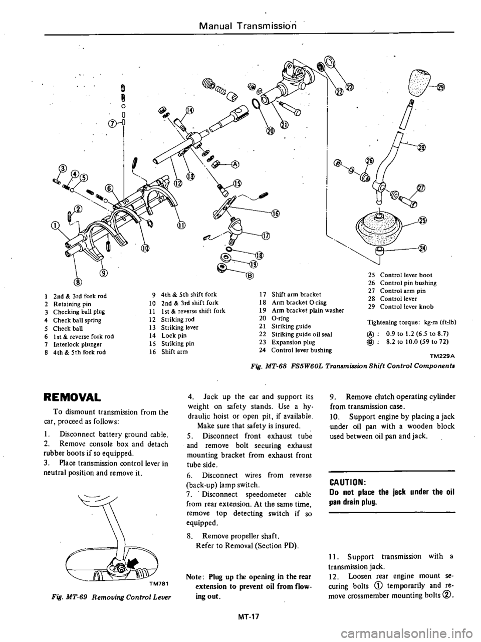
25
Control
lever
boot
26
Control
pin
bushing
27
Control
arm
pin
28
Control
lever
29
Control
lever
knob
1
2nd
3rd
fork
rod
9
4th
5th
shift
fork
17
Shift
arm
bracket
2
Retaining
pin
10
2nd
3rd
shift
fork
18
Arm
bracket
O
ring
3
Checking
ball
plug
11
Ist
reverse
shift
fork
19
Arm
bracket
plain
washer
4
Check
ball
spring
12
Striking
rod
20
O
ring
5
Check
ball
13
Striking
lever
21
S
lriking
guide
6
ht
reverse
fork
rod
14
Lock
pin
22
Striking
guide
oil
seal
7
Interlock
plunger
15
Striking
pin
23
Expansion
plug
8
4th
5th
fork
rod
16
Shift
arm
24
Control
lever
bushing
Tightening
torque
kg
m
fHb
@
0
9
to
1
2
6
5
to
8
7
@
8
2
to
to
O
59
to
72
TM229A
Fig
MT
68
FS5W60L
Transmission
Shift
Control
Components
REMOVAL
4
Jack
up
the
car
and
supporl
its
weight
on
safety
slands
Use
a
hy
draul
c
hoist
or
open
pit
if
available
Make
sure
that
safety
is
insured
S
Disconnect
front
exhaust
tube
and
remove
bolt
securing
exhaust
mounting
bracket
from
exhaust
front
tube
side
6
Disconnect
wires
from
reverse
back
up
lamp
switch
7
Disconnect
speedometer
cable
from
rear
extension
At
the
same
time
remove
top
detecting
switch
if
so
equipped
8
Remove
propeller
shaft
Refer
to
Removal
Section
PD
To
dismount
transmission
from
the
car
proceed
as
follows
Disconnect
battery
ground
cable
2
Remove
console
box
and
detach
rubber
boots
if
so
equipped
3
Place
transmission
control
lever
in
neutral
position
and
remove
it
CJi
J
TM781
Note
Plug
up
the
opening
in
the
rear
extension
to
prevent
oil
from
flow
ing
out
Fig
MT
69
Removing
Control
Lever
MT
17
9
Remove
clutch
operating
cylinder
from
transmission
case
10
Support
engine
by
placing
a
jack
under
oil
pan
with
a
wooden
block
used
between
oil
pan
and
jack
CAUTION
Do
not
place
the
jack
under
the
oil
pan
drain
plug
II
Support
transmission
with
a
transmission
jack
12
Loosen
rear
engine
mount
se
curing
bolts
CD
temporarily
and
re
move
crossmember
mounting
bolts
CV
Page 235 of 548
DISASSEMBLY
TRANSMISSION
CASE
DISASSEMBLY
1
Prior
to
disassembling
transmis
sion
thoroughly
wipe
off
dirt
and
grease
from
it
2
Drain
oil
thoroughly
3
Remove
dust
cover
from
trans
mission
case
Remove
release
bearing
and
with
drawallever
4
Remove
reverse
lamp
switch
and
top
detecting
switch
if
so
equipped
5
Remove
speedometer
pinion
as
sembly
6
Remove
nut
and
stopper
pin
bolt
from
rear
end
of
rear
extension
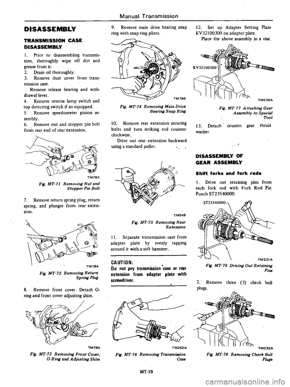
Fig
MT
71
Removing
Nut
and
Stopper
Pin
Bolt
7
Remove
return
spring
plug
return
spring
and
plunger
from
rear
exten
sion
@
@
Q
@
j
TM784
Fig
MT
72
Removing
Return
Spring
Plug
8
Remove
front
cover
Detach
0
ring
and
front
cover
adjusting
shim
1l
l
TM785
Fig
MT
73
Removing
Front
Cover
D
Ring
and
Adju
ting
Shim
Manual
Transmission
9
Remove
main
drive
bearing
snap
ring
with
snap
ring
pliers
Fig
MT
74
Removing
Main
Drive
Bearing
Snap
Ring
10
Remove
rear
extension
securing
bolts
and
turn
striking
rod
counter
clockwise
Drive
out
rear
extension
backward
using
a
standard
puller
TM548
Fig
MT
75
Removing
R
ar
Extension
11
Separate
transmission
case
from
adapter
plate
by
evenly
tapping
around
it
with
a
soft
hammer
CAUTION
00
not
pry
transmission
case
or
rear
extension
from
adapter
plate
with
screwdriver
TM262A
Fig
MT
76
Removing
Tran
miuion
Ca
e
MT19
12
Set
up
Adapter
Setting
Plate
KV32100300
on
adapter
plate
Place
the
above
assembly
in
a
vise
TM230A
Fig
MT
77
A
ttaching
Gear
Assembly
to
Special
Tool
13
Detach
counter
gear
thrust
washer
DISASSEMBLY
OF
GEAR
ASSEMBLY
Shift
forks
and
fork
rods
1
Drive
out
retaining
pins
from
each
fork
rod
with
Fork
Rod
Pin
Punch
ST23540000
TM231
A
Fig
MT
78
Driving
Out
Retaining
Pim
2
Remove
three
3
check
ball
plugs
TM232A
Fig
MT
79
Removing
Check
Ball
Plug
Page 246 of 548

No
A
mm
in
Manual
Ttansniissio
n
Adjusting
shim
mm
in
0
50
0
0197
0
55
0
0217
0
60
0
0236
0
6
0
9756
0
70
0
0276
0
75
0
0295
0
80
0
0315
I
2
3
4
5
6
7
6
05
to
6
09
0
2382
to
0
2398
6
10to
6
14
0
2402
to
0
2417
6
15
to
6
19
0
2421
to
0
2437
6
20
to
6
2
4
9
1
41
t
19
2457
6
25
to
6
29
0
2461
to
0
2476
6
30
to
6
34
0
2480
to
0
2496
6
35
to
6
39
0
2500
to
0
2516
TM816
Fig
MT
131
MetuUring
Front
CoV
r
Adju
ting
Shim
1
Transmission
case
2
Main
drive
gear
3
Adjusting
shim
4
Bearing
TM817
Fig
MT
132
Selecting
Front
CoV
r
Adju
ti1l8
shim
2
Clean
maling
surfaces
of
front
cover
and
transmission
case
3
Install
front
cover
to
transmission
case
with
the
adjUsting
shim
and
0
ring
in
place
@
Tight
ning
torque
Front
co
erinstallation
bolt
1
0
to
1
6
kg
m
7
to
12
ft
Ib
Outer
parts
assembly
I
Install
speedometer
pinion
assem
bly
and
install
securing
bolt
and
tighten
@
Tightening
torque
Speedometer
sl
locking
plate
bolt
0
3
to
0
5
kg
m
2
2
to
3
6
ft
lb
2
Install
reverse
lamp
switch
and
tighten
At
the
same
time
install
top
detecting
switch
if
so
equipped
Be
sure
to
apply
locking
sealer
before
installation
MT30
@
Ti
ltening
torque
Rewene
lamp
switch
and
top
detecting
switch
2
0
to
3
5
kg
m
14
to
25
fHb
3
Apply
a
light
coat
of
multi
purpose
grease
to
withdrawal
lever
release
bearing
ahd
bearing
sleeve
in
stall
them
on
transmission
case
After
connecting
them
with
holder
spring
install
dust
cover
to
transmis
sion
case
4
Install
control
lever
temporarily
and
move
shift
coritrol
lever
through
all
gears
to
make
sure
that
gears
op
rate
smoothly
5
InstaU
draiiI
plug
coated
with
sealant
in
place
@
Tightening
torque
Drain
plug
2
5
to
4
0
kg
m
18
to
29
fHb
6
Make
sure
that
main
drive
shaft
rotates
smoothly
in
Neutral
v
Jin
drive
gear
routing
torque
less
than
1
8
leg
em
1
6
in
Ib
Page 249 of 548

TIGHTENING
TORQUE
Ball
pin
Striking
lever
lock
nut
S
llft
arm
bracket
Mainshaft
bearing
retainer
screw
Mainshaft
lock
nut
Rear
extension
installation
bolt
Stopper
pin
bolt
Front
cover
installation
bolt
Speedometer
sleeve
lock
ing
plate
bolt
Top
detecting
switch
Reverse
lamp
switch
Neutral
switch
Return
spring
plug
Gear
oil
filler
plug
Gear
oil
drain
plug
Transmission
to
engine
installation
bolt
Tr
msmissiori
to
engihe
rear
plate
installation
bolt
Transmission
to
gusset
installation
bolt
Starting
motor
to
trans
inissi
n
installation
bolt
Rear
mounting
insulator
to
transmission
installation
bolt
Crossmember
mounting
bolt
Rear
engine
mount
installation
bolt
Clutch
operating
cylinder
installation
bolt
Propeller
shaft
to
differential
carrier
Control
lever
pin
installation
nut
Exhaust
mounting
bracket
to
exhaust
front
tube
FU
model
only
Manual
Transmission
F4W60L
2
0
to
3
0
14
to
22
0
9
to
1
2
6
5
to
8
7
0
7
to
1
0
5
1
to
7
2
1
6
to
2
2
12
to
16
0
5
to
0
8
3
6
to
5
8
1
0
to
1
6
7
to
12
0
3
to
0
5
2
2
to
3
6
2
0
to
3
5
14
to
25
2
0
to
3
5
14
to
25
0
5
to
1
0
3
6
to
7
2
2
5
to
4
0
18
to
29
2
5
to
4
0
18
to
29
1
6
to
2
2
12Jo
16
1
6
to
2
2
12
t
16
4
6
to
6
1
33
to
44
3
0
to
4
0
22
to
29
0
9
to
1
2
6
5
to
8
7
3
2
to
4
3
23
to
31
0
9
to
1
2
6
5
to
8
7
3
1
to
4
1
22
to
30
2
4
to
3
3
17
to
24
1
3
to
1
7
9
to
12
3
2
to
4
3
23
to
31
MT33
Unit
kg
m
ft
lb
FS5W60L
2
0
to
3
0
14
to
22
0
9
to
1
2
6
5
to
8
7
8
2
to
10
0
59
to
72
0
8
to
1
3
5
8
to
9
4
10
0
to
11
0
72
to
80
1
6
to
2
2
12
to
16
1
0
to
1
6
7
to
12
0
3
to
0
5
2
2
to
3
6
2
0
to
3
5
14
to
25
2
0
to
3
5
14
to
25
2
0
to
3
5
14
to
25
0
5
to
1
0
3
6
to
7
2
2
5
to
4
0
18
to
29
i
5
to
4
0
18
to
29
1
6
to
2
2
12
to
16
1
6
to
2
2
12
to
16
4
6
to
6
1
33
to
44
3
0
to
4
0
22
to
29
0
9
to
1
2
6
5
to
8
7
3
2
to
4
3
23
to
31
0
9
to
1
2
6
5
to
8
7
3
1
to
4
1
22
to
30
2
4
to
3
3
17
to
24
1
3
to
1
7
9
to
12
3
2
to
4
3
23
to
31
Page 279 of 548

Automatic
Transmission
MAJOR
REPAIR
OPERATION
SERVICE
NOTICE
FOR
DISASSEMBLY
AND
ASSEMBLY
I
It
is
advisable
that
repair
opera
tions
be
carried
out
in
a
dust
proof
room
2
Due
to
the
differences
of
the
engine
capacities
the
specifications
of
component
parts
for
each
model
s
transmission
may
be
different
They
do
however
have
common
adjust
ment
and
repair
procedures
as
well
as
cleaning
and
inspection
procedures
outlined
hereinafter
3
During
repair
operations
refer
to
Service
Data
and
Specific3ti
H1s
see
tion
for
the
correct
parts
for
each
model
4
Before
removing
any
of
subas
semblies
thoroughly
clean
the
outside
of
the
transmission
to
prevent
dirt
from
entering
the
mechanical
parts
5
Do
not
use
a
waste
rag
Use
a
nylon
or
paper
cloth
6
After
disassembling
wash
all
dis
assembled
parts
and
examine
them
to
see
if
there
3re
any
worn
damaged
or
defective
parts
and
how
they
are
affected
Refer
to
Service
Data
for
the
extent
of
damage
that
justifies
replacement
7
As
a
rule
packings
seals
and
similar
parts
once
disassembled
should
be
replaced
with
new
ones
TORQUE
CONVERTER
The
torque
converter
is
a
welded
construction
and
can
not
be
disas
sembled
INSPECTION
I
Check
torque
convert
for
any
sign
of
damage
bending
oil
leak
or
deformation
If
necessary
replace
2
Remove
rust
from
pilots
and
bosses
completely
If
torque
converter
oil
is
fouled
or
contaminated
due
to
burnt
clutch
flush
the
torque
converter
as
follows
I
Drain
oil
in
torque
converter
2
Pour
non
lead
gasoline
or
kero
sene
into
torque
converter
approxi
mately
0
5
liter
I
J
V
S
pt
U
Imp
pt
3
Blow
air
into
torque
converter
and
flush
and
drain
out
gasoline
4
Fill
torque
converter
with
torque
converter
oil
approximately
0
5
liter
I
J
V
S
pt
U
Imp
pt
5
Again
blow
air
into
torque
con
verter
and
drain
torque
converter
oil
TRANSMISSION
DISASSEM
LY
I
Drain
oil
from
the
end
of
rear
extension
Mount
transmission
on
Transmission
Case
Stand
ST07g70000
or
ST07860000
Remove
oil
pan
AT118
Fig
A
T
26
R
movin
g
Oil
Pan
2
Remove
bolts
securing
converter
housing
to
transmission
case
Remove
torque
converter
housing
3
Remove
speedometer
pinion
sleeve
bolt
Withdraw
pinion
4
Remove
downshift
solenoid
and
vacuum
diaphragm
Do
not
leave
dia
phragm
rod
at
this
stage
of
dis
assembly
Rod
is
assembled
in
top
of
vacuum
diaphragm
Fig
A
T
27
Dowmhift
Solenoid
and
Vacuum
Diaphragm
AT
27
5
Remove
bolts
which
hold
valve
body
to
transmission
case
Fig
AT
28
Removing
Valve
Body
6
Loosen
lock
nut
CV
on
piston
stem
CD
Then
tighten
piston
stem
in
order
to
prevent
front
clutch
drum
from
falling
when
oil
pump
is
withdrawn
AT121
Fig
AT
29
Loosening
Band
Se11
Jo
7
Pull
out
input
shaft
8
Withdraw
oil
pump
using
Sliding
Hammer
ST25850000
Do
not
allow
front
clutch
to
come
out
of
position
and
drop
onto
floor
AT122
Fig
AT
30
Removing
Oil
Pump
Page 309 of 548
Propeller
Shaft
Differential
Carrier
DIFFERENTIAL
CARRIER
fQ
@
1
11
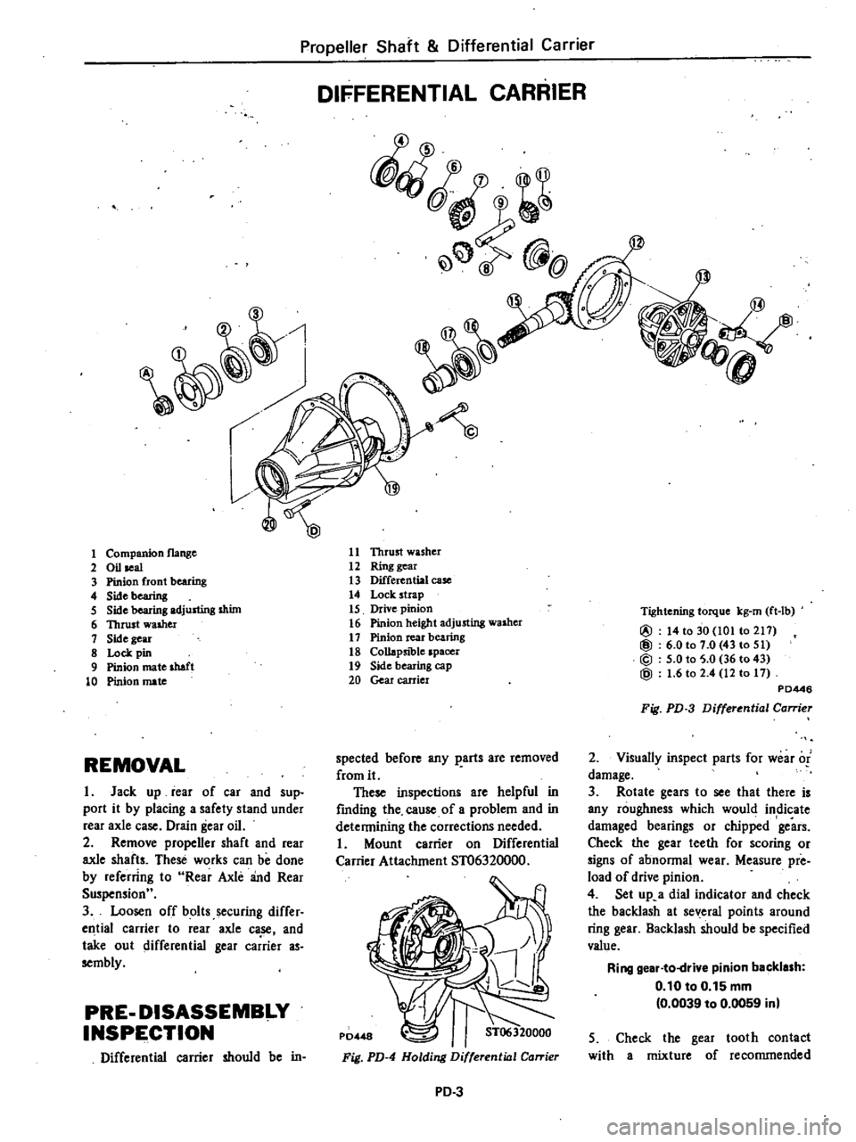
Thrust
washer
12
Ring
gear
13
Differential
case
14
Lock
strap
15
Drive
pinion
16
Pinion
height
adjusting
washer
17
Pinion
rear
bearing
18
Collapsible
spacer
19
Side
bearing
cap
20
Gear
carrier
1
Companion
flange
2
Oil
seal
3
Pinion
front
bearing
4
Sidebearing
5
Side
bearing
adjusting
shim
6
Thrust
walher
1
Side
gear
8
Lock
pin
9
Pinion
mate
shaft
10
Pinion
mate
Tightening
torque
kg
rn
ft
lb
@
14
to
30
101
to
211
@
6
0101
0
43
to
51
@
5
0
to
5
0
36
to
43
@
1
6
to
2
4
12
to
11
PD446
Fig
PD
3
Differential
Carrier
2
Visuany
inspect
parts
for
wear
of
damage
3
Rotate
gears
to
see
that
there
is
any
roughness
which
would
indicate
damaged
bearings
or
chipped
gears
Check
the
gear
teeth
for
scoring
or
signs
of
abnonnal
wear
Measure
pre
load
of
drive
pinion
4
Set
up
a
dial
indicator
and
check
the
backlash
at
several
points
around
ring
gear
Backlash
should
be
specified
value
Ring
gear
to
drive
pinion
backlash
0
10
to
0
15
mm
0
0039
to
0
0059
inl
spected
before
any
parts
are
removed
from
it
These
inspections
are
helpful
in
fmding
the
cause
of
a
problem
and
in
detennining
the
corrections
needed
Mount
carrier
on
Differential
Carrier
Attachment
ST06320000
REMOVAL
I
Jack
up
rear
of
car
and
sup
port
it
by
placing
a
safety
stand
under
rear
axle
case
Drain
gear
oil
2
Remove
propener
shaft
and
rear
axle
shafts
These
works
can
be
done
by
referring
to
Rear
Axle
and
Rear
Suspensionu
3
Loosen
off
bolts
securing
differ
ell
tial
carrier
to
rear
axle
ca
se
and
take
out
differential
gear
carrier
as
sembly
PRE
DISASSEMBI
Y
INSPE
CTION
Differential
carrier
should
be
in
5
Check
the
gear
tooth
contact
with
a
mixture
of
recommended
Fig
PD
4
Holding
Differential
Carrier
PD
3
Page 315 of 548

c
Flank
contact
Adjust
in
the
same
manner
as
in
b
t
P019S
Fig
PD
24
Flank
Contact
d
Face
contact
Adjust
in
the
same
manner
as
in
3
cf
P0196
Fig
PD
25
Face
Contact
e
Correct
tooth
contact
P0197
Fig
PD
26
Correct
Contact
Note
Change
in
thickness
of
adjust
ing
WlI8her
is
accompanied
by
change
in
backlash
Check
it
when
insteIIing
gear
Propeller
Shaft
Differential
Carrier
INSTALLATION
Installation
can
be
done
in
the
re
verse
order
of
removal
ifl
Tightening
torque
Gear
carrier
to
rear
axle
case
fixing
bolt
1
7
to
2
4
kg
m
12
to
17
ft
lbl
Drain
and
filler
plug
6
to
10
kg
m
43
to
72
ft
lbl
Gear
oil
quantity
0
9
liter
1
U
US
pt
1
Imp
pt
Note
a
Discard
gear
carrier
gasket
after
remom
Do
not
apply
sealant
to
the
gasket
b
Apply
sealant
to
bolts
securing
gear
carrier
case
to
rear
axle
housing
REPLACEMENT
OF
FRONT
OIL
SEAL
When
replacing
front
oil
seal
do
as
follows
1
Remove
differential
carrier
assem
bly
and
mount
it
on
Differential
Car
rier
Attachment
ST06320000
This
work
can
be
done
by
referring
to
Removal
procedure
2
Remove
side
bearing
caps
and
take
out
differential
case
assembly
Remove
drive
pinion
nut
and
extract
drive
pinion
assembly
Remove
oil
seal
These
works
can
be
done
by
re
ferring
to
Disassembly
procedure
PD
9
3
Install
a
new
oil
seal
in
gear
car
rier
using
Oil
Seal
Fitting
Tool
ST3340000l
Lubricate
cavity
between
seal
lips
with
recommended
multi
purpose
grease
when
installing
4
Place
a
new
collapsible
spacer
on
drive
pinion
and
lubricate
pinion
rear
bearing
with
gear
oil
5
Insert
companion
flange
into
oil
seal
Insert
drive
pinion
into
com
panion
flange
from
rear
of
gear
carrier
and
secure
them
in
position
by
tightening
nut
to
given
torque
con
firming
specified
preload
These
works
can
be
done
by
re
ferring
to
Adjustment
of
Drive
Pinion
Preload
procedure
6
Install
differential
case
assembly
into
gear
carrier
Measure
L
dimen
sion
backlash
with
specification
adjust
them
with
side
bearing
shims
The
works
can
be
done
by
re
ferring
to
Adjustment
of
Side
Bearing
Shims
procedure
7
Reinstall
differential
gear
carrier
assembly
rear
axle
shafts
and
pro
peller
shaft
Fill
up
differential
carrier
with
correct
gear
oil
CAUTION
a
Replacement
of
front
oil
seal
with
differential
carrier
assembly
install
ed
on
car
must
not
be
ellowed
due
to
used
collapsible
spacer
on
iu
model
b
Whenever
front
oil
seal
is
replaced
collepsible
spacer
must
be
replaced
Page 317 of 548
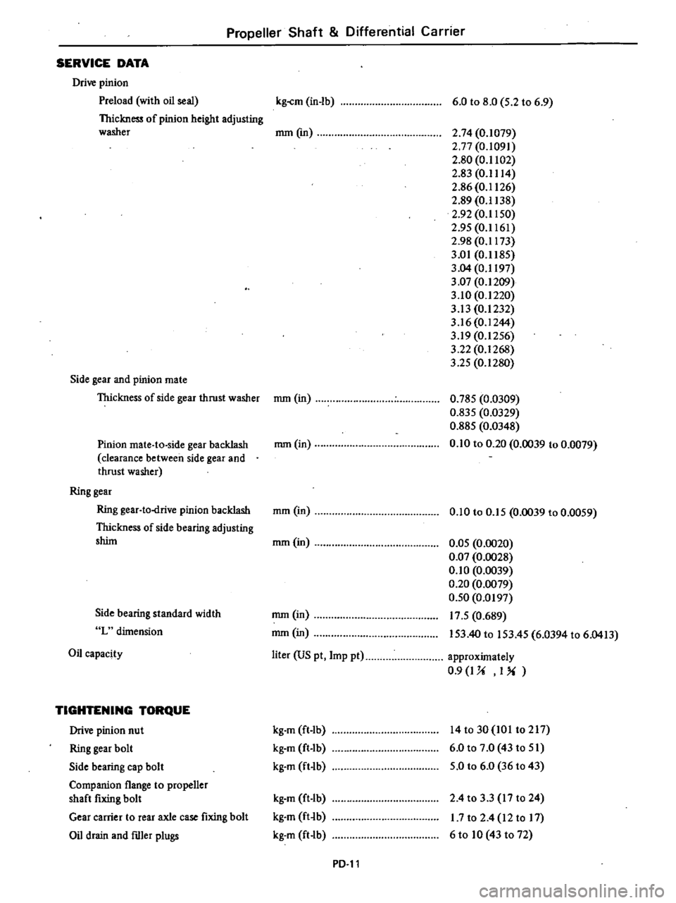
Propeller
Shaft
Differential
Carrier
SERVICE
DATA
Drive
pinion
Preload
with
oil
seal
Thickness
of
pinion
height
adjusting
washer
Side
gear
and
pinion
mate
Thickness
of
side
gear
thrust
washer
Pinion
mate
to
side
gear
backlash
clearance
between
side
gear
and
thrust
washer
Ring
gear
Ring
gear
to
drive
pinion
backlash
Thickness
of
side
bearing
adjusting
shint
Side
bearing
standard
width
L
dimension
Oil
capacity
TIGHTENING
TORQUE
Drive
pinion
nut
Ring
gear
bolt
Side
bearing
cap
bolt
Companion
flange
to
propener
shaft
fixing
bolt
Gear
carrier
to
rear
axle
case
fixing
bolt
Oil
drain
and
ftller
plugs
kg
cm
in
lb
6
0
to
8
0
5
2
to
6
9
mm
em
2
74
0
1079
2
77
0
1091
2
80
0
1102
2
g3
0
1114
2
86
0
1126
2
89
0
1138
2
92
0
1150
2
95
0
1161
2
98
0
1173
3
01
0
1185
3
04
0
1197
3
07
0
1209
3
10
0
1220
3
13
0
1232
3
16
0
1244
3
19
0
1256
3
22
0
1268
3
25
0
1280
mm
in
0
785
0
0309
0
835
0
0329
0
885
0
0348
0
10
to
0
20
0
0039
to
0
0079
mmOn
mm
in
0
10
to
0
15
0
0039
to
0
0059
mm
in
0
05
0
0020
0
Q7
0
0028
0
10
0
0039
0
20
0
0079
0
50
0
0197
17
5
0
689
153
40
to
153
45
6
0394
to
6
0413
mm
in
mm
in
liter
US
pt
Imp
pt
approximately
0
9
I
U
I
kg
m
ft
Ib
kg
m
ft
Ib
kg
m
ft
lb
14to30
IOI
t0217
6
0
to
7
0
43
to
51
5
0
to
6
0
36
to
43
kg
m
ft
Ib
kg
m
ft
b
kg
m
ft
lb
2
4
to
3
3
17
to
24
1
7
to
2
4
12
to
17
6
to
10
43
to
72
PD
ll
Page 320 of 548
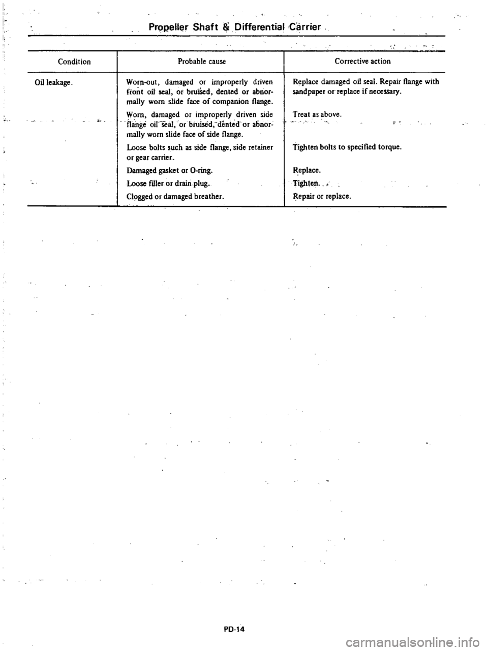
Condition
Oil
leakage
Pro
eller
Shaft
8i
Differential
Carrier
Probable
cause
Worn
Jut
damaged
or
improperly
driven
front
oil
seal
or
bruiSed
dented
or
abnor
mally
worn
slide
face
of
companion
flange
Worn
damaged
or
improperly
driven
side
flange
oil
seal
or
bruised
dented
or
abnor
mally
worn
slide
face
of
side
flange
Loose
bolts
such
as
side
flange
side
retainer
or
gear
carrier
Damaged
gasket
or
O
ring
Loose
fdler
or
drain
plug
Cl9gged
or
damaged
breather
PD
14
Corrective
action
Replace
damaged
oil
seal
Repair
flange
with
sandpapel
or
replace
if
necessary
Treat
as
above
Tighten
bolts
to
specified
torque
Replace
Tighten
Repair
or
replace