drain bolt DATSUN 210 1979 Service Manual
[x] Cancel search | Manufacturer: DATSUN, Model Year: 1979, Model line: 210, Model: DATSUN 210 1979Pages: 548, PDF Size: 28.66 MB
Page 17 of 548
Engine
Tune
up
BASIC
MECHANICAL
SYSTEM
ADJUSTING
INTAKE
AND
EXHAUST
VAL
fE
CLEARANCE
Note
After
tightening
cYlinder
head
bolts
adjust
intake
and
exhaust
valve
clearances
Valve
clearance
ai
ljustment
cannot
be
made
while
the
engine
is
in
opera
tion
To
adjust
proceed
as
follows
I
Start
engine
and
warm
it
up
uritil
water
temperature
indicator
points
to
the
middle
of
gauge
Then
stop
engine
2
Rotate
crankshaft
to
bring
No
I
cylinder
in
top
dead
center
on
its
compression
stroke
3
Remove
valve
rocker
cover
Adjust
valve
clearance
at
following
four
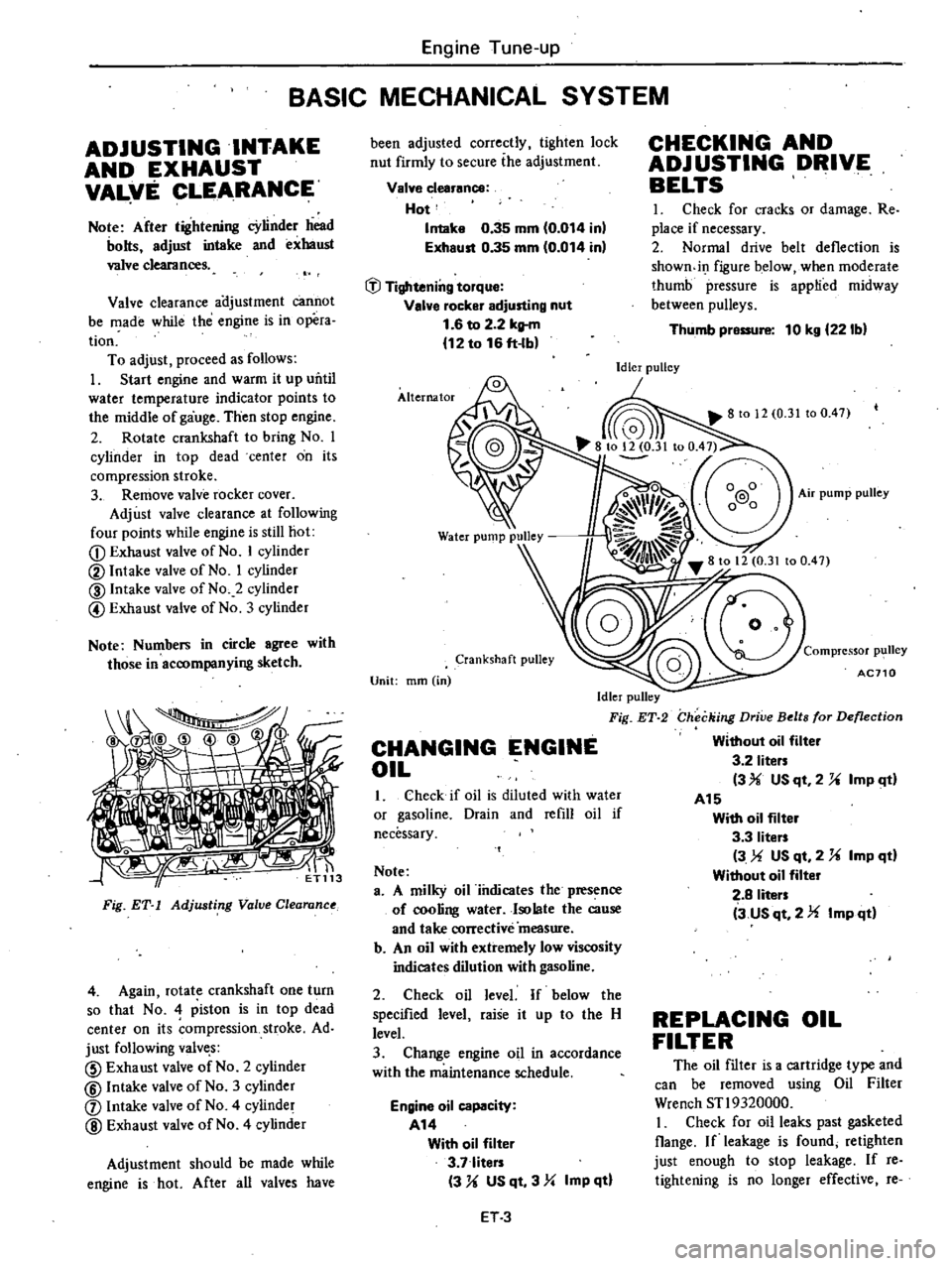
points
while
engine
is
still
hot
CD
Exhaust
valve
of
No
I
cylinder
@
Intake
valve
of
No
I
cylinder
@
Intake
valve
of
No
2
cylinder
@
Exhaust
valve
of
No
3
cylinder
Note
Numbers
in
circle
agree
with
those
in
accompanying
sketch
tiri
Fig
ET
1
Adjusting
Value
Clearanu
4
Again
rotate
crankshaft
one
turn
so
that
No
4
piston
is
in
top
dead
center
on
its
ompression
stroke
Ad
just
following
valve
s
CID
Exhaust
valve
of
No
2
cylinder
@
Intake
valve
of
No
3
cylinder
j
Intake
valve
of
No
4
cylinder
@
Exhaust
valve
of
No
4
cylinder
Adjustment
should
be
made
while
engine
is
hot
After
all
valves
have
been
adjusted
correctly
tighten
lock
nut
firmly
to
secure
ihe
adjustment
Valve
clearance
Hot
Intake
0
35
mm
0
014
inl
Exhaust
0
35
mm
0
014
in
tJl
Tightening
torque
Valve
rocker
adjusting
nut
1
6
to
2
2
kltm
12
to
16
ft
lb
Alternator
Crankshaft
pulley
Unit
mm
in
Idler
pulley
Fig
ET
2
CHANGING
ENGINE
OIL
1
Check
if
oil
is
diluted
with
water
or
gasoline
Drain
and
refill
oil
if
necessary
Note
a
A
milky
oil
iiulicates
the
presence
of
cooling
water
Isolate
the
cause
and
take
corrective
measure
b
An
oil
with
extremely
low
viscosity
indicates
dilution
with
gasoline
2
Check
oil
level
If
below
the
specified
level
raise
it
up
to
the
H
level
3
Change
engine
oil
in
accordance
with
the
maintenance
schedule
Engine
oil
capacity
A14
With
oil
filter
3
7
liters
3
U
US
qt
3
Yo
Imp
qtl
ET3
CHECKING
AND
ADJUSTING
DRIVE
BELTS
I
Check
for
cracks
or
damage
Re
place
if
necessary
2
Normal
drive
belt
deflection
is
showndI
figure
below
when
moderate
thumb
pressure
is
applied
midway
between
pulleys
Thumb
pressure
10
kg
221bl
Idler
pulley
Compressor
p1
111ey
AC710
Checking
Drive
Belts
for
Deflection
Without
oil
filter
3
2
liters
3
USqt
2
U
ImP
ltl
A15
With
oil
filter
3
3
liters
3
US
qt
2
U
Imp
qd
Without
oil
filter
2
8
liters
3
us
qt
2
Imp
qd
REPLACING
OIL
FILTER
The
oil
filter
is
a
cartridge
type
and
can
be
removed
using
Oil
Filter
Wrench
STl9320000
I
Check
for
oil
leaks
past
gasketed
Oange
If
leakage
is
found
retighten
just
enough
to
stop
leakage
If
reo
tightening
is
no
longer
effective
re
Page 67 of 548

t
IGHTENING
TORQUE
Cylinder
head
bolt
Rocker
shaft
bracket
bolt
ain
bearing
cap
bolt
Flywheel
fixing
bolt
Drive
plate
fixing
bolt
Al4
AlS
Connecting
rod
cap
nut
Camshaft
sprocket
bolt
Locating
plate
bolt
Valve
rocker
adjusting
nut
Oil
strainer
bolt
Oil
pan
bolt
Oil
pan
drain
plug
Timing
chain
cover
bolt
Crank
pulley
bolt
Water
pump
bolt
Fuel
pump
bolt
Spark
plug
Engine
mounting
securing
bolt
Engine
Mechanical
Unit
kg
iii
ft
lb
7
0
to
7
5
51
to
54
2
0t02
5
14to
18
5
0
to
6
0
36
to
43
8
0
to
9
0
58
to
65
8
0
to
9
0
58
to
65
8
5
to
9
5
61
to
69
3
2
to
3
8
23
to
27
4
0
to
4
8
29
to
35
0
5
to
0
8
3
6
to
5
8
1
6
to
2
2
12to
16
0
9
to
I
4
6
5
to
10
1
0
4
to
0
6
2
9
to
4
3
2
0
to
3
0
14
to
22
0
5
to
0
7
3
6
to
5
1
15to
20
l08
to
145
0
9
to
I
4
6
5
to
1O
l
0
9
to
I
4
6
5
to
10
1
1
5
to
2
0
11
to
14
1
9
to
2
5
14to
18
EM
30
Page 80 of 548
DESCRIPTION
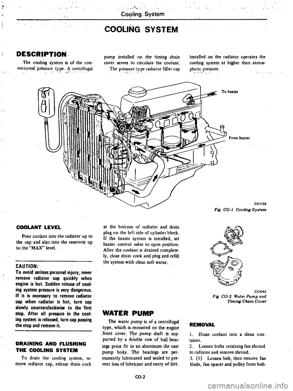
The
cooling
system
is
of
the
con
ventional
pressure
type
A
centrifugal
1P
a
COOLANT
LEVEL
Pour
coolant
into
the
radiator
up
to
the
cap
and
also
into
the
reservoir
up
to
the
MAX
level
CAUTION
To
avoid
serious
personal
injury
never
remove
radiator
cap
quickly
when
engine
is
hot
Sudden
release
of
cool
ing
system
pressure
is
very
dangerous
If
it
is
necessary
to
remove
radiator
cap
when
radiator
is
hot
turn
cap
slowly
counterclockwise
to
the
first
step
After
all
pressure
in
the
cool
ing
system
is
released
turn
cap
passing
the
stop
and
remove
it
DRAINING
AND
FLUSHING
THE
COOLING
SYSTEM
To
drain
the
cooling
system
re
move
radiator
cap
release
drain
cock
C09ling
System
COOLING
SYSTEM
pump
installed
on
the
timing
chain
cover
serves
to
circulate
the
coolant
The
pressure
t
pe
radiator
filler
cap
at
the
bottom
of
radiator
and
drain
plug
on
the
left
side
of
cylinder
block
If
the
heater
system
is
instaDed
set
heater
control
valve
to
open
position
Mter
the
coolant
is
drained
complete
ly
close
drain
cock
and
plug
and
refdl
the
system
with
clean
soft
water
WATER
PUMP
The
water
pump
is
of
a
centrifugal
type
which
is
mounted
on
the
engine
front
cover
TJ
te
pump
shaft
is
sup
ported
by
a
double
row
of
baD
bear
ings
press
fit
in
an
aluminum
die
cast
pump
body
The
bearings
are
per
manently
lubricated
and
sealed
to
pre
vent
loss
of
lubricant
and
entry
of
dirt
CO
2
installed
on
the
radiator
operates
the
cooling
system
at
higher
than
atmos
pheric
pressure
To
heater
From
heater
C0126
Fig
COol
Cooling
System
C0042
Fig
CO
2
Water
Pump
and
Timing
Chain
Couer
REMOVAL
1
Drain
coolant
into
a
clean
con
tainer
2
Loosen
bolts
retaining
fan
shroud
to
radiator
and
remove
shroud
3
I
Loosen
belt
then
remove
fan
blade
fan
spacer
and
pulley
from
hub
Page 82 of 548
Cooling
System
TEM
COUPLlNG
Non
Califomia
model
equipped
with
air
conditioning
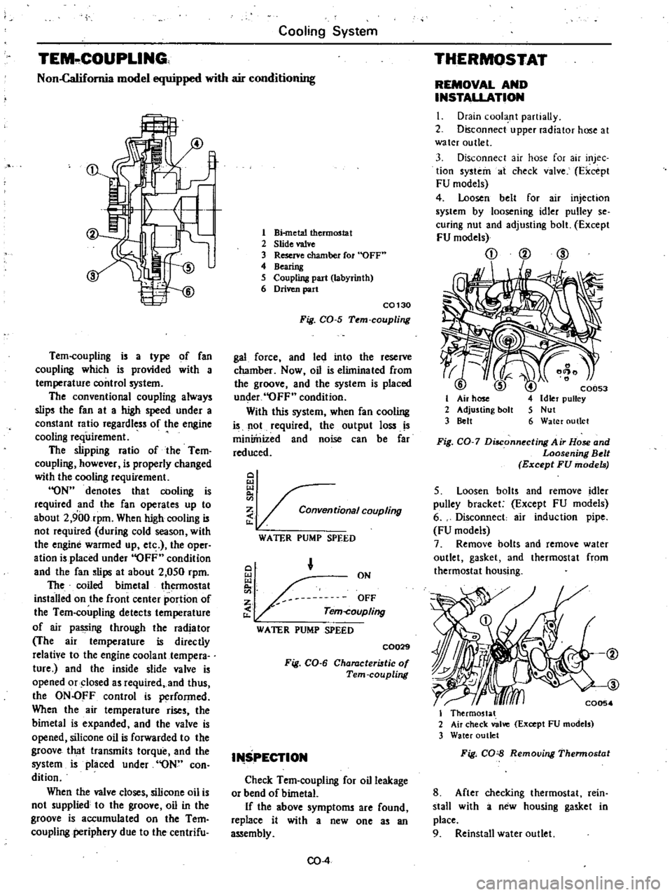
Tem
coupling
is
a
type
of
fan
coupling
which
is
provided
with
a
temperature
control
system
The
conventional
coupling
always
slips
the
fan
at
a
high
speed
under
a
constant
ratio
regardless
of
the
engine
cooling
requirement
The
slipping
ratio
of
the
Tem
coupling
however
is
properly
changed
with
the
cooling
requirement
ON
denotes
that
cooling
is
required
and
the
fan
operates
up
to
about
2
900rpm
When
high
cooling
is
not
required
during
cold
season
with
the
engine
warmed
up
etc
the
oper
ation
is
placed
under
OFF
condition
and
the
fan
slips
at
about
2
050
rpm
The
coiled
bimetal
thermostat
installed
on
the
front
center
portion
of
the
Tem
coupling
detects
temperature
of
air
passing
through
the
radiator
The
air
temperature
is
directly
relative
to
the
engine
coolant
tempera
ture
and
the
inside
slide
valve
is
opened
or
closed
as
required
and
thus
the
ON
OFF
control
is
performed
When
the
air
temperature
rises
the
bimetal
is
expanded
and
the
valve
is
opened
silicone
oil
is
forwarded
to
the
groove
that
transmits
torque
and
the
system
is
placed
under
ON
con
dition
When
the
valve
closes
silicone
oil
is
not
supplied
to
the
groove
oil
in
the
groove
is
accumulated
on
the
Tem
coupling
periphery
due
to
the
centrifu
1
Bi
metal
thermostat
2
Slide
valve
3
Reserve
chamber
fOl
OFF
4
Bearing
5
Coupling
part
labyrinth
6
Driven
part
C0130
Fig
CO
5
Tem
coupling
gal
force
and
led
into
the
reserve
chamber
Now
oil
is
eliminated
from
the
groove
and
the
system
is
placed
under
OFF
condition
With
this
system
when
fan
cooling
is
not
required
the
output
loss
IS
miniinized
and
noise
can
be
far
reduced
Q
i
tionalCOUPling
WATER
PUMP
SPEED
Q
ON
OFF
Tem
coupling
WATER
PUMP
SPEED
C0029
Fig
CO
6
Characteristic
of
Tern
coupling
I
SPECTION
Check
Tem
coupling
for
oil
leakage
or
bend
of
bimetaL
If
the
above
symptoms
are
found
replace
it
with
a
new
one
as
an
assembly
CO
4
THERMOSTAT
REMOVAL
AND
INSTALLATION
I
Drain
cool
nt
partiaUy
2
Disconnect
upper
radiator
hose
at
water
outlet
3
Disconnect
air
hose
for
air
injec
tion
systein
at
check
valve
Fxcept
FU
models
4
Loosen
belt
for
air
injechon
system
by
loosening
idler
pulley
se
curing
nut
and
adjusting
bolt
Except
FU
models
CD
@
ID
I
2
3
C0053
Idler
pulley
Nut
Water
outlet
Fig
CO
7
Disconnecting
Air
Hose
and
Loosening
Belt
Except
FU
models
5
Loosen
bolts
and
remove
idler
pulley
bracket
Except
FU
models
6
Disconnect
air
induction
pipe
FU
models
7
Remove
bolts
and
remove
water
outlet
gasket
and
thermostat
from
thermostat
housing
I
Thermostat
2
Air
check
valve
Except
FU
models
3
Water
outlet
Fig
CO
Removing
Thennostat
8
After
checking
thermostat
rein
stall
with
a
new
housing
gasket
in
place
9
Reinstall
water
outlet
Page 83 of 548
10
Replenish
coolant
and
check
for
leaks
INSPECTION
I
Submerge
thermostat
in
hot
water
SOC
90F
above
the
specified
temperature
Refer
to
Service
Data
and
Specifications
2
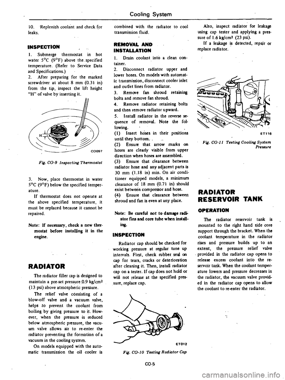
After
preparing
for
the
marked
screwdriver
at
about
8
mm
0
31
in
from
the
tip
inspect
the
lift
height
H
of
valve
by
inserting
it
f
C0097
Fig
CO
g
In
pecting
Thermostat
3
Now
place
thermostat
in
water
SoC
90F
below
the
specified
temper
ature
If
thermostat
does
not
operate
at
the
above
specified
temperature
it
must
be
replaced
because
it
cannot
be
repaired
Note
If
necessary
check
a
new
ther
mostat
before
installing
it
in
the
engine
RADIATOR
The
radiator
filler
cap
is
designed
to
maintain
a
pre
set
pressure
0
9
kgfcm2
13
psi
above
atmospheric
pressure
The
relief
valve
consisting
of
a
blow
off
valve
and
a
vacuum
valve
helps
to
prevent
the
coolant
from
boiling
by
giving
pressure
to
it
How
ever
when
the
pressure
is
reduced
below
atmospheric
pressure
the
vacu
wn
valve
allows
air
to
re
enter
the
radiator
preventing
the
formation
ofa
vacuum
in
the
cooling
system
On
models
equipped
wi
th
the
au
to
malic
transmission
the
oil
cooler
is
Cooling
System
combined
with
the
radiator
to
cool
transmission
fluid
REMOVAL
AND
INSTALLATION
1
Drain
coolant
into
a
clean
con
tainer
2
Disconnect
radiator
upper
and
lower
hoses
On
models
with
automat
ic
transmission
disconnect
cooler
inlet
and
ou
tlet
lines
from
radiator
3
Rem
Ne
fan
shroud
retaining
bolts
and
remove
fan
shroud
4
Remove
radiator
retaining
bolts
and
then
remove
radiator
upward
S
I
nstaD
radiator
in
the
reverse
se
quence
of
removal
Note
the
fol
lowing
I
Insert
hoses
in
their
positions
until
they
bottom
2
Ensure
that
arrow
marks
on
hoses
are
clearly
visible
from
upper
direction
when
hoses
are
assembled
3
Ensure
that
clearance
between
radiator
hose
and
any
adjacent
parts
is
30
mm
1
18
in
min
On
air
condi
tioner
equipped
models
a
minimum
clearance
of
18
mm
0
71
in
should
exist
between
compressor
and
hose
4
Ensure
that
clearance
be
tween
shroud
and
fan
is
even
at
any
place
Note
Be
careful
not
to
damage
radi
ator
fins
and
core
tube
when
install
ing
INSPECTION
Radiator
cap
should
be
checked
for
working
pressure
at
regular
tune
up
intelVals
First
check
rubber
seal
on
cap
for
tears
cracks
or
deteriontion
after
cleaning
it
Then
ins
taD
radiator
cap
on
a
tester
If
cap
does
not
hold
or
will
not
release
at
the
specified
pres
sure
replace
cap
Fig
CO
lO
Testing
Radiator
Cap
CO
5
Also
inspect
radiator
for
leakage
using
cap
tester
and
applying
a
pres
sure
of
1
6
kgfcm2
23
psi
If
a
leakage
is
detected
repair
or
replace
radiator
ET116
Fig
CO
II
Testing
Cooling
System
Prtuurt
RADIATOR
RESERVOIR
TANK
OPERATION
The
radiator
reservoir
tank
is
mounted
to
the
right
hand
side
core
support
through
the
bracket
When
the
coolant
temperature
in
the
radiator
rises
and
pressure
builds
up
to
an
extent
the
pressure
relief
valve
provided
in
the
radiator
cap
opens
to
release
excess
coolant
into
the
re
servoir
tank
When
the
coolant
temper
ature
lowers
and
pressure
decreases
in
the
radiator
the
vacuum
valve
provid
ed
in
the
radiator
cap
opens
to
allow
the
coolant
to
re
enter
the
radiator
Page 85 of 548
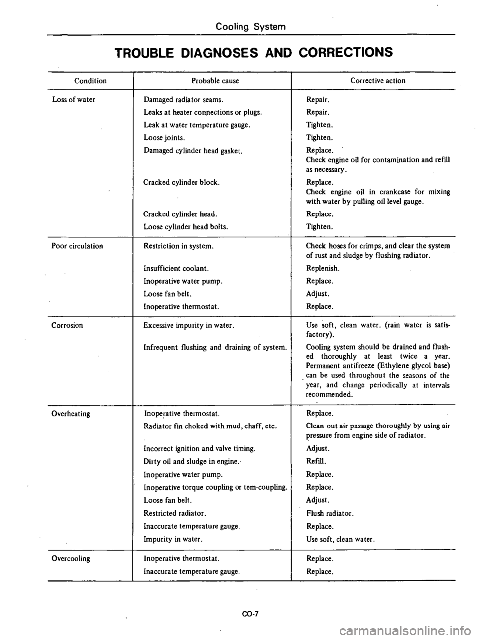
Condition
Loss
of
water
Poor
circulation
Corrosion
Overheating
Over
cooling
Cooling
System
TROUBLE
DIAGNOSES
AND
CORRECTIONS
Probable
cause
Damaged
radiator
seams
Leaks
at
heater
connections
or
plugs
Leak
at
water
temperature
gauge
Loose
joints
Damaged
cylinder
head
gasket
Cracked
cylinder
block
Cracked
cylinder
head
Loose
cylinder
head
bolts
Restriction
in
system
Insufficient
coolant
Inoperative
water
pump
Loose
fan
belt
Inoperative
thermostat
Excessive
impurity
in
water
Infrequent
flushing
and
draining
of
system
Inoperative
thermostat
Radiator
fin
choked
with
mud
chaff
etc
Incorrect
ignition
and
valve
timing
Dirty
oil
and
sludge
in
engine
Inoperative
water
pump
Inoperative
torque
coupling
or
tem
coupling
Loose
fan
belt
Restricted
radiator
Inaccurate
temperature
gauge
Impurity
in
water
Inoperative
thermostat
Inaccurate
temperature
gauge
CO
7
Corrective
action
Repair
Repair
Tighten
Tighten
Replace
Check
engine
oil
for
contamination
and
reml
as
necessary
Replace
Check
engine
oil
in
crankcase
for
mixing
with
water
by
pulling
oil
level
gauge
Replace
Tighten
Check
hoses
for
crimps
and
clear
the
system
of
rust
and
sludge
by
flushing
radiator
Replenish
Replace
Adjust
Replace
Use
soft
clean
water
rain
water
is
satis
factory
Cooling
system
should
be
drained
and
flush
ed
thoroughly
at
least
twice
a
year
Permanent
antifreeze
Ethylene
glycol
base
can
be
used
throughout
the
seasons
of
the
year
and
change
periodically
at
intervals
recommended
Replace
Clean
out
air
passage
thoroughly
by
using
air
pressure
from
engine
side
of
radiator
Adjust
Refill
Replace
Replace
Adjust
Flush
radiator
Replace
Use
soft
dean
water
Replace
Replace
Page 143 of 548
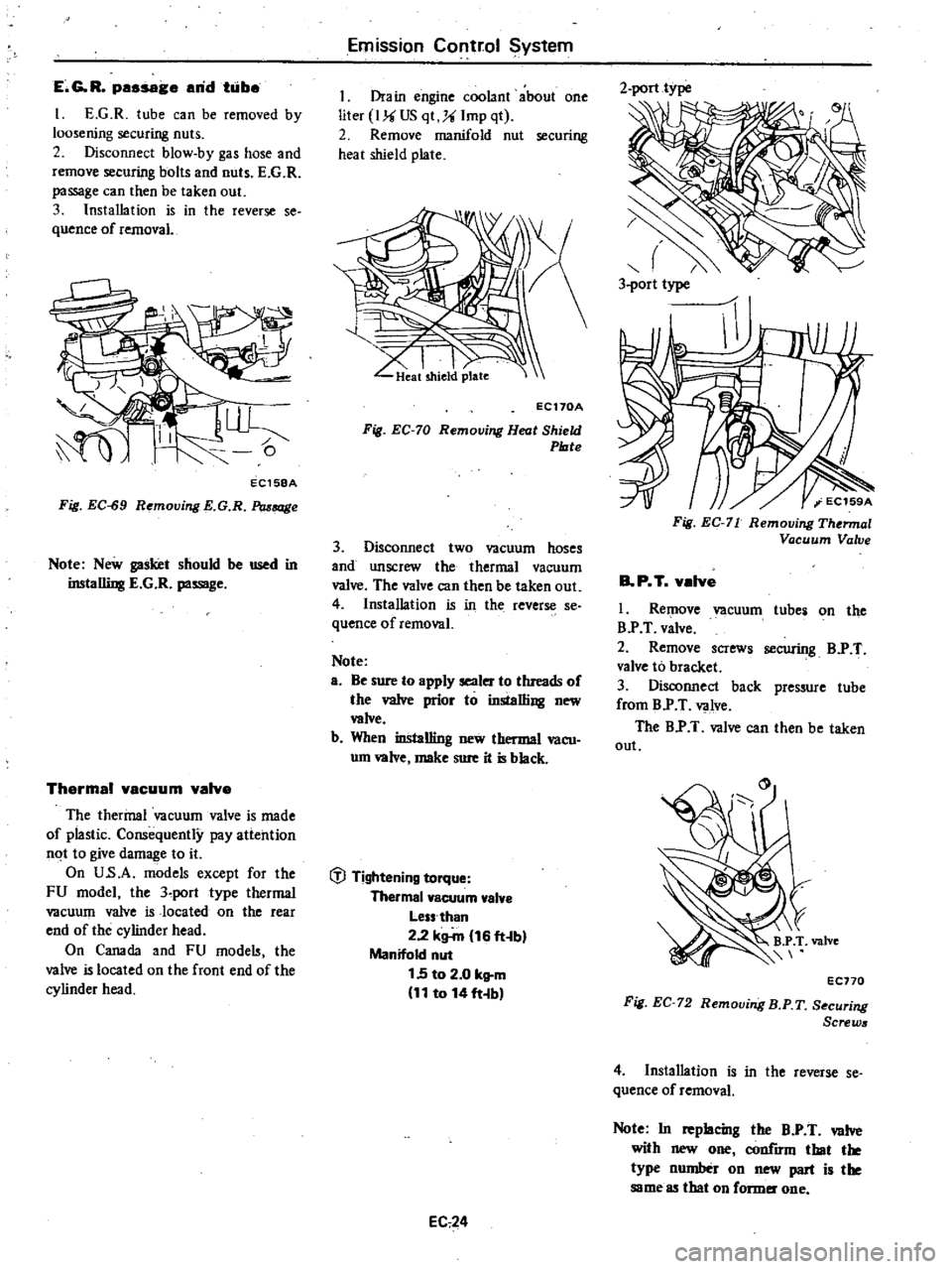
E
G
R
passage
arid
taibe
I
E
G
R
tube
can
be
removed
by
loosening
securing
nuts
2
Disconnect
blow
by
gas
hose
and
remove
securing
bolts
and
nuts
E
G
R
passage
can
then
be
taken
out
3
Installation
is
in
the
reverse
se
quence
of
removal
EC158A
Fig
EC
S9
Removing
E
G
R
Passage
Note
New
gasket
should
be
used
in
installing
E
G
R
passage
Thermal
vacuum
valve
The
thermal
vacuum
valve
is
made
of
plastic
Consequently
pay
attention
not
to
give
damage
to
it
On
U
s
A
models
except
for
the
FU
model
the
3
port
type
thermal
vacuum
valve
is
located
on
the
rear
end
of
the
cylinder
head
On
Canada
and
FU
mode
the
valve
is
located
on
the
front
end
of
the
cylinder
head
Emission
Corltr
ol
System
I
Drain
engine
coolant
about
one
liter
I
US
qt
Imp
qt
2
Remove
manifold
nut
securing
heat
shield
plate
I
I
LIkat
shield
plate
EC170A
Fig
EC
70
Removing
Heat
Shield
Plate
3
Disconnect
two
vacuum
hoses
and
unscrew
the
thermal
vacuum
valve
The
valve
can
then
be
taken
out
4
Installation
is
in
the
reverse
se
quence
of
removal
Note
a
Be
sure
to
apply
sealer
to
threads
of
the
valve
prior
to
installing
new
wive
b
When
installing
new
thermal
vacu
um
wive
make
sure
it
is
black
t
J
Tightening
torque
Thermal
vacuum
valve
Less
than
2
2
kg
m
16
ft
b
Manifold
nut
1
5
to
2
0
kg
m
11
to
14
ft
b
EC
24
2
port
type
3
port
type
Fig
EC
71
Removing
Thermal
Vacuum
Valve
B
P
T
valve
I
Remove
vacuum
tube
on
the
B
P
T
valve
2
Remove
screws
securing
B
P
T
valve
to
bracket
3
Disconnect
back
pressure
tube
from
B
P
T
valve
The
B
P
T
valve
can
then
be
taken
out
EC770
Fig
EC
72
Removing
B
P
T
S
curing
Screws
4
Installation
is
in
the
reverse
se
quence
of
removal
Note
In
replacing
the
B
P
T
valve
with
new
one
h
that
the
type
number
on
new
part
is
the
same
85
that
on
former
one
Page 199 of 548

REMOVAL
It
is
much
easier
to
remove
engine
and
transmission
as
a
single
unit
than
to
remove
alone
After
removal
engine
can
be
separated
from
the
transmission
assembly
WARNING
a
Place
wheel
chocks
in
fronl
of
front
wheels
and
in
rear
of
rear
wheels
b
Be
sure
to
hoist
engine
in
a
safe
manner
c
You
should
not
remove
engine
until
exhaust
system
has
com
pletely
cooled
off
Otherwise
you
may
burn
your
self
and
or
fire
may
break
out
in
fuel
line
Note
Fender
coven
should
be
used
to
protect
car
body
1
Disconnect
battery
ground
cable
from
battery
terminal
and
fusible
link
at
wire
connector
2
Remove
hood
as
follows
CAUTION
Have
an
assistant
help
you
so
as
to
prevent
damage
to
body
I
Mark
hood
hinge
locations
on
hood
to
facilitate
reinstallation
2
Support
hood
by
ltand
and
re
move
bolts
securing
it
to
hood
hinge
being
careful
not
to
let
hood
slip
when
bolts
are
removed
See
Fig
ER
2
3
Remove
hood
from
hood
hinge
f
Il
I
BF133A
Fig
ER
2
Removing
Hood
Remove
under
cover
Drain
radiator
coolant
and
engine
3
4
oil
5
Disconnect
upper
and
lower
hoses
from
radiator
and
disconnect
oil
cooler
hoses
automatic
transmission
only
6
Remove
four
bolts
securing
radia
Engine
Removal
Installation
tor
to
body
and
detach
radiator
after
removing
radiator
shroud
7
Remove
air
cleaner
assembly
from
carburetor
as
follows
1
Remove
fresh
air
duct
from
air
cleaner
2
Remove
hot
air
duct
from
air
cleaner
3
Loosen
air
cleaner
band
bolt
4
Disconnect
air
cleaner
to
air
pump
hose
at
air
cleaner
5
Disconnect
air
cleaner
ta
rocker
cover
hose
at
rocker
cover
6
Disconnect
air
cleaner
to
A
B
valve
hose
at
air
cleaner
7
Disconnect
air
cleaner
to
related
vacuum
hoses
at
air
cleaner
8
Disconnect
accelerator
control
wire
from
carburetor
9
Disconnect
the
following
cables
wires
and
hoses
Wire
to
auto
choke
heater
Wire
to
throttle
opener
cut
solenoid
or
throttle
switch
Wire
to
fuel
cut
solenoid
Wire
to
vacuum
switching
valve
High
tension
cable
between
igni
tion
coil
and
distributor
Battery
cable
to
starter
motor
Wire
to
distributor
Wire
to
thermal
transmitter
Wire
to
alternator
Engine
ground
cable
oil
pressure
switch
and
engine
harness
No
2
See
Fig
ER
3
o
1
Ground
cable
2
Engine
harness
No
2
3
Oil
pressure
switch
Fig
ER
3
EA368
Disconnecting
Cable
and
Wire
Fuel
hose
at
fuel
pump
and
fuel
return
hose
at
connection
Air
pump
air
cleaner
hose
Carbon
canister
hoses
Heater
inlet
and
outlet
hoses
if
so
equipped
ER
3
Vacuum
hose
of
brake
booster
at
intake
manifold
Air
conditioner
equipped
model
10
Remove
compressor
belt
To
remove
loosen
idler
pulley
nut
and
adjusting
bolt
1
Remove
air
pump
2
Remove
compressor
retaining
bolts
and
move
compressor
toward
fender
to
facilitate
removal
of
engine
Nole
Never
discharge
gas
from
com
pressor
while
work
is
being
per
formed
II
Compressor
EA478
Fig
ER
4
Location
of
Air
Compressor
3
Disconnect
vacuum
hose
of
air
conditioner
from
connector
of
intake
manifold
4
Remove
F
i
C
D
actuator
from
bracket
II
Remove
clutch
operating
cylin
der
from
clutch
housing
manual
trans
mission
only
dJ
Tightening
torque
Clutch
operating
cylinder
E
A3
to
clutch
housing
3
1
to
4
1
kg
22
to
30
ft
lbl
Fig
ER
5
Removing
Clutch
Operating
Cylinder
Page 219 of 548

I
ht
2nd
fork
r
2
3rd
top
fork
rod
3
Reverse
fork
rod
4
Retaining
pin
5
I
t
2nd
shift
fork
6
3rd
top
shift
fork
7
Checking
ball
plug
8
Check
ban
spring
9
Check
ball
10
Interlock
plunger
11
S
topper
ring
12
Shift
rod
A
bracket
13
Reverse
shift
fork
14
Lock
pin
15
Striking
lever
Manual
Transmission
16
Striking
rod
17
Return
spring
plug
18
Reverse
check
spring
19
Return
pring
20
Plunger
21
D
ring
22
Stopper
pin
bolt
23
Striking
guide
assembly
24
Striking
guide
oil
seal
REMOVAL
To
dismount
transmission
from
the
car
proceed
as
follows
Disconnect
battery
ground
cable
2
Remove
console
box
and
detach
rubber
boots
if
so
equipped
3
Place
transmission
control
lever
in
neutral
position
and
remove
it
m
TM781
Fig
MT
4
Removing
Control
Lever
@
@
25
Control
lever
bushing
26
Expansion
plug
27
Control
pin
bushing
28
Control
arm
pin
29
Control
lever
o
Tightening
torque
kg
m
ft
lb
@
0
5
to
0
8
3
6
tn
5
8
@
1
3
to
1
7
9
to
12
Fig
MT
3
F4W60L
Tra11lmiBSion
Shift
Control
Components
TM094A
4
Jack
up
the
car
and
support
its
weight
on
safety
stands
Use
a
hy
draulic
hoist
or
open
pit
if
available
Make
sure
that
safety
is
insured
5
Disconnect
front
exhaust
tube
and
remove
bolt
securing
exhaust
mounting
bracket
from
exhaust
front
tube
side
6
Disconnect
wires
from
reverse
back
up
lamp
switch
7
Disconnect
speedometer
cable
from
rear
extension
At
the
same
time
removey
top
detecting
switch
if
so
equipped
8
Remove
propeller
shaft
Refer
to
Removal
Section
PO
Note
Plug
up
the
opening
in
the
rear
extension
to
prevent
oil
from
flow
ing
out
MT
3
9
Remove
clutch
operating
cylinder
from
transmission
case
10
Support
engine
by
placing
a
jack
under
oil
pan
with
a
wooden
block
used
between
oil
pan
and
jack
CAUTION
00
not
place
the
jack
under
the
oil
pan
drain
plug
11
Support
transmission
with
a
transmission
jack
12
Loosen
rear
engine
mount
se
curing
bolts
CD
temporarily
and
re
move
crossmember
mounting
bolts
V
Page 221 of 548
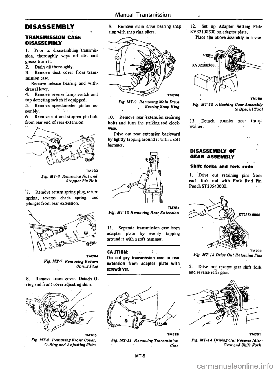
DISASSEMBLY
TRANSMISSION
CASE
DISASSEMBLY
I
Prior
to
disassembling
traiIsmis
sian
thoroughly
wipe
off
dirt
and
grease
from
it
2
Drain
oil
thoroughly
3
Remove
dust
cover
from
trans
mission
case
Remove
release
bearing
and
with
drawallever
4
Remove
reverse
lamp
switch
and
top
detecting
switch
if
equipped
5
Remove
speedometer
pinion
as
sembly
6
Remove
nut
and
stopper
pin
bolt
from
rear
end
of
rear
extension
TM783
Fig
MT
6
Removing
Nut
and
Stopper
Pin
Bolt
7
Remove
return
spring
plug
return
spring
reverse
check
spring
and
plunger
from
rear
extension
@
@
j
TM784
Fig
MT
7
Rt
moving
Return
Spring
Plug
8
Remove
front
cover
Detach
0
ring
and
front
cover
adjusting
shim
TM785
Fig
MT
B
Removing
Front
Cover
a
Ring
and
Adju
ting
Shim
Manual
Transmission
9
Remove
main
drive
bearing
snap
ring
with
snap
ring
pliers
o
TM188
Fig
MT
9
Rt
mouing
Main
Drive
BNring
Snap
Ring
10
Remove
rear
extenSion
secUring
baits
and
turn
the
striliing
rod
clock
wise
Drive
out
rear
extension
backward
by
lightly
ta
pping
around
it
with
a
soft
hammer
TM787
Fig
MT
10
Removing
Rear
Extemion
11
Separate
transmission
case
from
adapter
plate
by
evenly
tapping
around
it
with
a
soft
hammer
CAUTION
Do
not
pry
transmission
case
or
rear
extension
from
edapter
plate
with
screwdriver
TM788
Fig
MT
II
Removing
Tronsmiuion
COSf
MT
5
12
Set
up
Adapter
Setting
Plate
KV32100300
on
adapter
plate
Place
the
above
assembly
in
a
vise
TM789
Fig
MT
12
A
ttaching
Gear
A
mbly
to
Special
Tool
13
Detach
counter
gear
thrust
washer
DISASSEMBLY
OF
GEAR
ASSEMBLY
Shift
forks
and
fork
rods
I
Drive
out
retaining
pins
from
each
fork
rod
with
Fork
Rod
Pin
Punch
ST23540000
TM790
Fig
MT
13
Drive
Out
Retaining
Pim
2
Drive
out
reverse
gear
shift
fork
and
reverse
idief
gea
TM791
Fig
MT
14
Driving
Out
Re
1dkr
Gear
and
Shift
Fork